Bestandskraft
-
Posts
154 -
Joined
-
Last visited
Content Type
Profiles
Forums
Events
Everything posted by Bestandskraft
-
Although as far as I can tell none of the changelogs mention it, the issue of crosswinds aloft causing the aircraft to roll is no longer present in 1.5.3.50487.
-
Shkval does not see S-8OM illumination
Bestandskraft replied to Frederf's topic in Bugs and Problems
I can confirm that as of 1.5.3.50487, in the Shkval optics only objects get illuminated by S-8OM rockets, but not the terrain. This is regardless of Shkval or game zoom level. -
Lonewolf Callsign: Bestandskraft Side: Wherever you guys need me (if no preference I'll take Blue) Mi-8, Ka-50, MiG-21Bis, A-10C, UH-1H (at some point)
-
Hey guys, I have two questions regarding system failures for which I could not find answers when searching for "system failures" on the forums. 1) When "Random System Failures" are enabled in the "Misc." tab in the Options menu, and such a failure subsequently occurs in a mission... a) will the game randomly select one of the possible failure modes listed in the "Failures" tab of the mission editor for the respective aircraft, or b) could it be that the random failure is one that cannot be specifically selected in the mission editor? Put another way, has anyone ever experienced a "Random System Failure" in any module that was NOT in the list of failures that can be set in the mission editor? If so, is anyone aware if somewhere in the DCS file structure a file exists where these additional possible failures can be viewed? 2) Has anyone in any module ever experienced a system failure due to aircraft mishandling (except structural damage) that was NOT in the list of failures that can be set in the mission editor? Thanks!
-
I would like to point out that this issue has already been in part discussed in this thread, and was specifically mentioned in this post. I suspect the "uncommanded roll" issue and the wind issue that this thread here deals with are in some way linked.
-
My apologies. I have actually had their Battle Book for a while, not realizing there was an associated thread. From reading it it seems the 476th are either using RL (Western) data/bomb ranges (which probably means those are quite close to the in-game values), or they have derived the data from in-game testing. I was hoping to avoid the latter, hence my request for a calculator released by ED. Just to be clear: I already know how to calculate a z-sled in principle, I only lack empirical data (mostly in-game bomb ranges and TOFs for different release parameters) to feed my formulas. Just using the 476th z-sleds is not an option since at the moment I'm flying the MiG-21 whose tactical flight envelope is just too different. You are of course correct. Assuming you are on parameters and use your altimeter to determine when to pickle, you will hit even without the sight. Its main purpose then would be lateral alignment and the avoidance of altimeter lag (which is, I believe, not simulated in DCS).
-
@dotChuckles: Nice video, however it does not explain how you guys obtained the BDU-33 bomb range upon which your z-sleds are based. Also I could not spot a sight setting in your video (resolution is not the best though). Based on what I know about the 476th I would assume you have access to CWDS and/or the -34 tables, however this is not particularly helpful in this context since a) we do not know whether the in-game ballistics are identical to real-world ballistics, and b) comprehensive data for Russian/Eastern bombs do not seem to be available online, and c) the sight setting would differ for each aircraft due to different angles of attack/incidence at release parameters. If you could verify that using the real-world data has been successful for you that would solve point a) [at least for those who have access to the relevant material], but not points b) and c).
-
As I stated in my OP ("attack planning"), this would be the purpose of the calculator I'm suggesting/requesting.
-
Would have posted this in the "DCS Wishlist" sub-forum, but the "new thread" button does not show up for me there. On to business: For attack planning, especially for some of the older modelled aircraft, it would be nice to have a ballistic calculator for at least all the unguided bombs available, either integrated into the game or as an external applet. Although some real-world ballistic tables can be found on the internet, it is unclear whether the in-game weapons are coded to behave exactly as their real-world counterparts (probably not), so those tables are mostly useless. Since ED knows which formulas they use to model weapon ballistics in the game, I imagine it would be relatively easy to make such a calculator available for the end user. For those unfamiliar with ballistic tables/calculators: The user enters data such as release velocity, dive angle, release altitude, stick size and bomb spacing, and the calculator determines e.g. bomb range, time of flight, impact angle, impact velocity, pattern length, and sight depression at release. Any chance ED could provide us with such a tool?
-
Question about the real MiG-21bis speed brake switch
Bestandskraft replied to Bestandskraft's topic in MiG-21Bis
Hey finger, thanks for your help. In your picture it looks as if the speed brake switch moves forward and aft, as opposed to outboard (depressed) and inboard (released). This would mean that the switch in the virtual cockpit moves in a different axis than in the real jet, so neither a) nor b) are correct. Can you clarify? -
Looking at the current MiG-21bis virtual cockpit implementation of the speed brake switch, it seems as if in the real jet: a) The speed brake switch works like the radio button, i.e. the speed brakes extend and remain extended for as long as the speed brake switch is depressed. Once the pilot lets go of the switch, the switch returns to its original (extended) position and the speed brakes retract. b) The speed brake switch is a toggle button: Once the pilot presses the switch, the speed brakes extend, and the speed brake switch is held (possibly by a spring or a latch) in the depressed position even if the pilot lets go of the switch. The pilot then has to depress the speed brake switch once more to unlatch it and cause it to return to its original (extended) position, which also causes the speed brakes to retract. For anyone familiar with the real MiG-21bis, is the speed brake switch of type a) or b)? Or does it work completely differently, meaning that the virtual cockpit implementation is currently wrong?
-
35. Page 44 of the MiG-21 manual implies that it should be possible to receive at least the localizer signal of a PRMG out to 40 km. In the game, reception of both localizer and glide slope starts at 25 km, which is consistent with page 116 of the game manual. Page 44 of the MiG-21 manual further states that Landing mode should be selected at no more than ±10° degrees from the final approach azimuth. Additionally page 100 and 101 imply that the HSI (CCI) localizer channel failure warning flag closes its window (presumably meaning the localizer signal is being received) at 10-12° of azimuth deviation. Assuming the drawing on page 104 of the MiG-21 manual is to scale, the coverage zone displayed there is also approximately ±10°. In the game, according to page 116 of the game manual and verified by in-game behaviour, the localizer is received only within 2° of the centerline. Moreover, Table 11 on page 101 of the MiG-21 manual and page 108 indicate that a proper PRMG glide path is characterised by the altitude in hundreds of meters equaling half the distance to the runway in kilometers. This equates to a 2.86° (thus, approximately 3°) glide path. According to page 116 of the game manual and as easily confirmed by in-game testing, the simulated MiG-21's PRMG glide path is 4°. The manufacturers of the PRMG system (POLYOT) confirm on their web-site that the localizer of at least the most modern version of the PRMG has a minimum range of 45 km and a horizontal coverage zone of ±15°, while the glideslope has an 18 km range as well as a slope angle limit of 2-4°, which might indicate that 3° is the desired average angle. See http://www.polyot.ru/emitent/Eng/PRMG-76UM%20En%20Polet%202012.pdf. The relatively restricted forward visibility in the MiG-21 during landing approach also supports the 3° instead of a 4° glide path theory. 36. Page 45 of the MiG-21 manual implies that in Letdown/Proceed mode, the HSI will provide both vertical and horizontal steering information. In the game, only vertical steering is provided; a specific azimuth cannot be selected.
-
As some further food for thought on theory 1, page 44 of the MiG-21 manual states that Landing mode should be selected at no more than ±10° degrees from the final approach azimuth. In addition to what I already stated in the OP, page 101 (as well as page 100 et al) also imply that the HSI (CCI) localizer channel failure warning flag closes its window (presumably meaning the localizer signal is being received) at 10-12° of azimuth deviation, which should occur simultaneously with the relative bearing pointer indicating that azimuth delta AND pointing at the "4". In the game, according to page 116 of the game manual and verified by in-game behaviour, the localizer is received only within 2° of the centerline. Since we have an actual real-world photograph standing against an actual real-world manual, the most likely explanation seems to be different mod states of instruments and approach aids.
-
According to Western doctrine, turns in IMC conditions are normally performed at 30° AOB. Since the whole point of an RSBN box is to land the aircraft in IMC conditions, I can hardly believe that it is designed around a bank angle of 45° (I'm not saying that you say it is). Of course Russian doctrine might be/might have been different, but since Russians have the same cochlea and are therefore susceptible to spatial disorientation in the same measure as Westerners I'd only believe that if I saw it in writing in a real-world document.
-
Just used a ruler on the photo effte provided, and this confirms that the real life instrument, like the virtual one, uses 35° and 15° for the "3" and "4", respectively. The "2" might be 34° instead of 35°, but this discrepancy should be insignificant. This seems to disprove theory 1, but contradicts page 101, which states that the final turn commencement index is 10-12° off the final approach course. Maybe there are/were different versions of the HSI. I'm still confused about how a "proper" RSBN box is supposed to look.
-
I really appreciate your trying to help solve the issue, but (as so often on the internet) there seem to be fundamental communication difficulties between the two of us (English is not my native language). Our conversation seems to be running in circles. I have obviously failed on various occasions during this conversation to get my point accross, and since I cannot figure out where my comments are ambiguous or misleading, I will now cease clarification attempts. No hard feelings. If anyone can spot the reason why mvsgas and I don't understand each other, feel free to jump in. :D
-
Setting the AUX 2-Pos Nozzle CTRL switch to the UP position closes the nozzle regardless of throttle position unless the afterburner is selected, in which case the nozzle remains open. The nose cone is not relevant for the EPs in question.
-
The supposed feature that the ФОРС. МАКС. switch does more than JUST disable the afterburner. As I already stated in post #5, the RL manual does not contain any additional information applicable to the issue at hand.
-
Please find attached a track and corresponding .acmi showing my unsuccessful attempt to fly a "by-the-book" RSBN box. effte, I understand your box works as advertised. If at all possible please upload a track or .acmi. Tacview-20150614-171816-DCS.txt.acmi.zip RSBN box.trk
-
The link I provided links to a real MiG-21 manual, and as I stated in the original post, the in-game manual has the same procedures for the EP in question. As to your explanation, sounds very reasonable. If this could be confirmed with a real-world manual, LN might consider implementing this feature in the game.
-
Correct. This causes a loss of thrust which during takeoff with heavy loads and/or insufficient runway length makes it impossible to get airborne. For any further discussion it would be helpful if you downloaded the MiG-21 manual from the link I provided; the book is also available digitally e.g. at http://www.avialogs.com/en/aircraft/ussr/mikoyangurevitch/mig-21/mig-21bis-pilot-s-flight-operating-instructions.html.
-
Neither the game manual nor the MiG-21 manual I'm referring to, unless I have overlooked something, explicitly mention secondary engine controls except for the mere existence of an emergency manual nozzle control (AUX 2-Pos Nozzle CTRL, АВАР. ВКЛ. 2xПОЗ. СОПЛА), a facility to manually open the derumble doors (anti-surge shutters) and a facility to manually control the nose cone. Neither manual explains what these switches do on a technical/engineering level. Meaningful (yet obviously incomplete) information is given only in the context of emergency procedures. There is no explict statement that the ФОРС. МАКС. switch enables a secondary engine control per se.
-
I'll call that theory 5. While this is certainly a possibility, it does not explain how the aircraft is supposed to reach the 015° @ 17-21 km point ("4") coming from the 035° @ 23-25 km point ("3"). Theory 5 also contradicts page 122 of the game manual, which depicts the RSBN box as a quasi-rectangle, not a trapezoid.
-
Thanks for your reply. How do you account for the fact that the ФОРС. МАКС. switch is supposed to be used not only during afterburner flameouts, but also during an inadvertent opening of the nozzle during takeoff at full throttle and during an airborne jet nozzle failure?
-
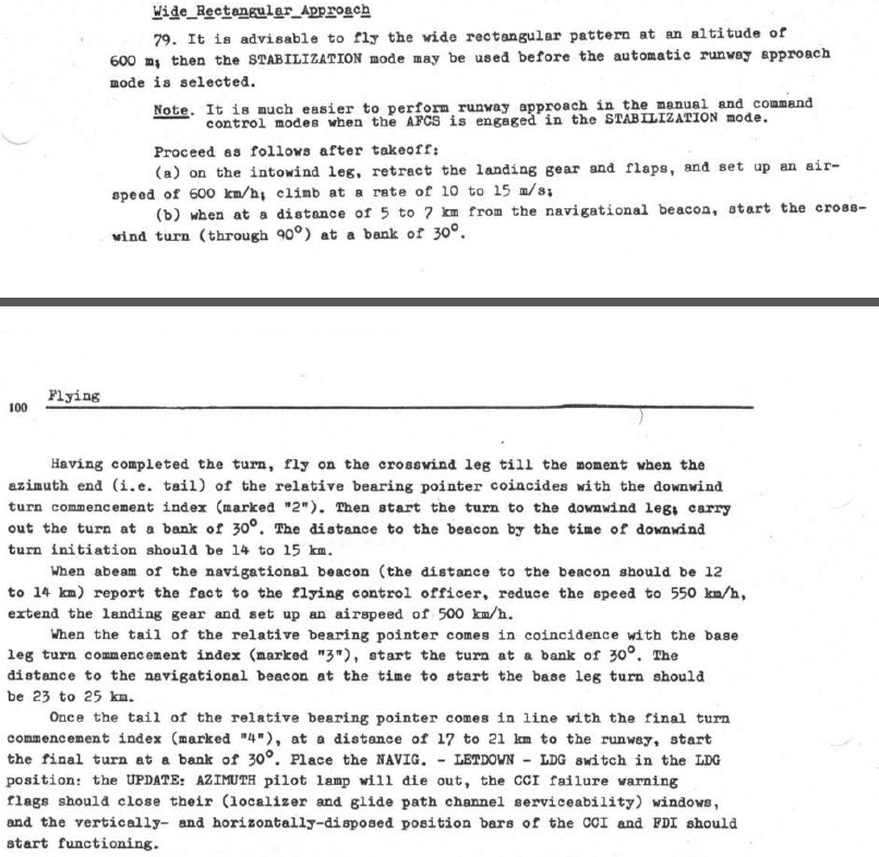
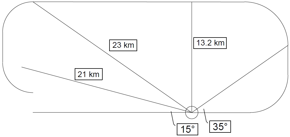
Pages 99-100 of the "MiG-21 Pilot's Operating Instructions", a .pdf of which can be found linked at http://forums.eagle.ru/showthread.php?t=138880, describe the RSBN box ("Wide Rectangular Approach") that is detailed on pages 120-122 of the game manual in a somewhat different way. I have been unsuccessfully trying to recreate the supposedly "realistic" RSBN box, a to-scale drawing of which is attached. By looking at the in-game HSI marks (2, 3, 4) I have visually derived the depicted bearings of approximately 35° from the approach course for the downwind and base turns, as well as 15° for the turn to final. Crosswind and downwind turn radii have been drawn to fit the ranges/bearings given in the description and are more or less consistent with actual turn radii at the mandated speeds and a bank angle of 30°. The given distances for the crosswind and downwind initiation as well as the distance abeam the station are approximately what can be observed in-game and calculated mathematically. However, it seems to be impossible to get the aircraft to a point 17-21 km away from and at a 15° bearing off the station while simultaneously adhering to the previous (and congruous) box parameters. Also, even if this were possible, starting the final turn at 500 km/h and 30° AoB at the given position results in a significant undershoot. Please note that the mentioned issues arise not just in the drawing, but in the same way when actually trying to fly the box in the game "by the book". I have four theories why this might be: 1) The "4" mark is incorrectly placed in the game. This theory is supported by page 101 of the MiG-21 manual, which states that the final turn commencement index is 10-12° off the final approach course, not 15° as I see it in the game. When adjusting the final turn bearing to 10° in my drawing, the undershoot problem is virtually solved, however, the aircraft will still fly a 23 km instead of a 21 km base (remember that base distance is supposed to be 17-21 km, so the drawing is already very conservative). 2) The real-world manual's description of the box is wrong. 3) I am not understanding the manual correctly. 4) The RSBN box base turn is not designed to be a 90° turn, but an approximate 135° turn. This would be consistent with the drawing on page 104 of the MiG-21 manual, and it would be partially consistent with page 89 of the manual, which states that in a visual pattern, the base turn is a 100-110° turn (the number of degrees still does not match, which might however be easily explained by one being a visual, the other an instrument maneuver). However, it seems unlikely that such an important fact would not be explicitly stated in the manual. Also, even with a 135° turn, the aircraft barely reaches the 21 km point. It should be noted however, that a 135° turn would cause the aircraft to reach the 17 km point if a 10° bearing was assumed (see point 1). Maybe both 1) and 4) are correct. Then again, if the 135° turn theory is valid, there would be no need for a "4" mark at all. Does anyone have any information that might explain these discrepancies? Alternatively, could anyone post a track or an .acmi of an RSBN box flown successfully according to the MiG-21 manual?