
maciekish
-
Posts
40 -
Joined
-
Last visited
Content Type
Profiles
Forums
Events
Everything posted by maciekish
-
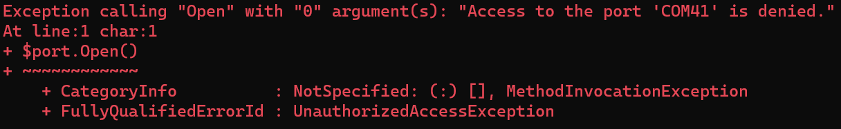
Sounds like either a permission issue or port in use. 1) First, try rebooting. I know it sounds stupid but COM ports have a weird habits of getting "stuck" in Windows. 2) Make sure the old Hub is not running, and nothing else is using the COM port. 3) Try running connect-serial-port from an elevated command prompt, press Start, type command prompt, and click "Run as Administrator". If that doesn't work, try something else and report the results: Open PowerShell and run $port = new-object System.IO.Ports.SerialPort COM3, 9600, None, 8, one $port.Open() Make sure to replace COM3 with your COM port number. For example, if the port is busy, you will get this response:

-

How To: DCS-BIOS RS-485 Bus with MAX485-based breakout boards
maciekish replied to FSFIan's topic in Home Cockpits
If anyone is still looking into this, there is now an integrated solution at dcsbioskit.com And i recommend staying away from the AliExpress $0.20 chips because ~20% of them are lemons. -
Sorry for necroing this, found it by accident. Its not any of the issues suggested. Its a buffer overflow caused by how the RS485 slave code is written. Was pulling my hair over this for 6 months. I have suggested a fix here which eliminates the issue.
-
I've tried the Discord but there aren't many people with that deep Arduino and RS485 knowledge, and the ones that do are understandably quite busy. Ill give the Nano a try but it won't be usable in many instances where the issue manifests, because i need either the pin count or the ram/program space. I want to avoid USB because of the additional cabling and COM-ports, but if its impossible then its impossible.
-
@No1sonuk Hi, thanks for your time, i really appreciate it. To clarify, the direct-drive of the LEDs is done properly via transistors + PWM via ULN2003A on the negative side, so no power is drawn from the Arduino, and its dimmable programatically. While i can certainly try a MAX7219, it would be a step back in development as i already have hardware for individual LED control. Will a MAX7219 library really be faster than direct register writes for 48 LEDs? I'm afraid the library code will add more overhead than the direct register writes, but I'm no expert on that matter. I tried a different LED controller before, don't remember which one but i had the same issue, inconsistent and dropped updates, which is why i decided to try low-level fast direct writes. Regarding the Arduinos, I'm using my own hardware consisting of customized Nanos and Megas. This panel indeed uses a mega, and i could possibly try a Nano, but that would mean 2-3 Arduinos for something as simple as a caution panel which is not ideal, especially considering i have already handled the power delivery to the LEDs. Since everything works fine over USB (approximately same amount of data), I'm instead suspecting that this has something to do with the Arduino not handling interrupts properly. For example, in Protocol.cpp, it looks like interrupts get disabled for RS485 slaves. Could you perhaps shed some light on this? I would much rather fix the underlying issue as this applies to displays as well, and if i can't even drive a Nextion over hardware serial, thats a big problem, and another reason i'm suspecting the MAX7219 won't really help. So to summarize, considering things are working over USB but not RS485 i draw the conclusion that there is a software issue in DCS-BIOS in RS485 mode. If you, or anyone else is knowledgeable enough to address this, i may be willing to pay up for the help, as this is a very serious issue for me. I'm in the process of designing and producing a special dev-kit PCB which will include master & slave on one board with appropriate test-points to troubleshoot this, and it will be made available to anyone who seriously considers fixing the root cause of this issue.
-
Hi, I've been pulling my hair with this for a long time, seems like when the Arduino is too busy drawing something on screen, or just toggling some LEDs, data gets missed on the RS485 bus. All the sketches i've tested work over USB with the same Arduino, but exhibit the exact same issue when run over RS485. If its a display, it either misses updates completely, misses half the screen, or starts writing out random data from the RS485 stream, even including the DCS-BIOS synchronization sequence on screen as text "UUUU". I even tried a simpler panel, the caution panel with direct register access for toggling the LEDs and its still too slow just blinking ~10 LEDs. If i reduce the number of LEDs to 2, it works perfectly. Here is an example of the caution panel of the A-10C, the blinking LEDs should be blinking at a steady pace, not take pauses like they do in the video below. Here is the code, i dont think it can be optimized much more than that... https://github.com/maciekish/warthogathome/blob/master/Arduino/23_Caution_Panel/23_Caution_Panel.ino Has anyone else run into these issues? Is DCS-BIOS handling the RS485 interrupts properly? Am i missing something completely different? IMG_3331.mp4
-
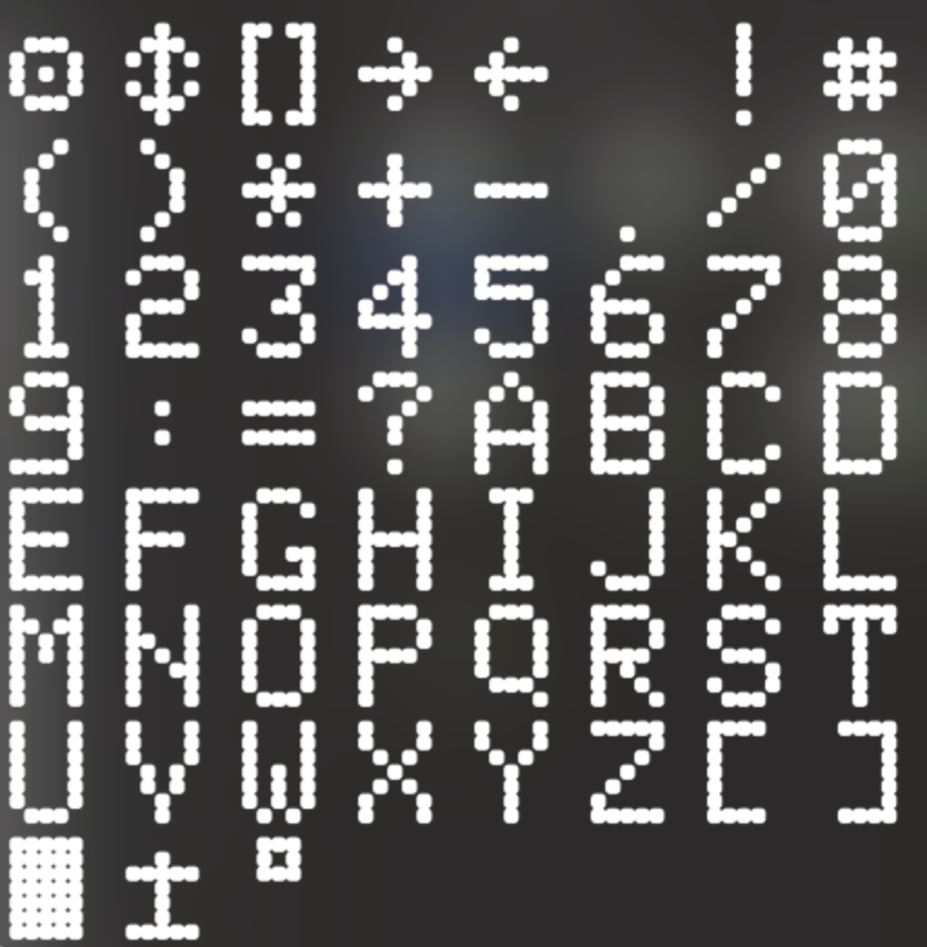
For futre reference, here are the special characters for the CDU BRANCH_L, arrow to the right, 0xBB BRANCH_R, arrow to the left, 0xAB ROTARY, up/down arrow, 0xAE DATA_ENTRY, "[]", 0xA1 SYS_ACTION, "bullseye", 0xA9 DEGREE, °, 0xB0 FILLED, █ cursor, 0xB6 INC_DEC, ± symbol, 0xB1
-
I added a pull request as a stop-gap solution until static addressing can be implemented https://github.com/DCSFlightpanels/dcs-bios/pull/177
-
Ofc i understand that, sorry if i wasnt clear enough. That link doesnt work for me unfortunately, says it opened my Discord client but nothing happens, tried 2 browsers, no messages about it being blocked or whatever -.- Any chance you can share a screenshot of the workaround please? Nvm i just logged in through the browser, forgot thats an option. Thanks anyway
-
Switches etc dont use addresses, they just send a message so it only impacts things like ligths and maybe servos etc. Only have 5 panels done, i'm sure i will run into more issues if it continues like this. Why don't they just add the stuff att the end instead of in the middle of the damn file Or just manually assign the addresses, looks like 10 min work per module which only has to be done once, if it was made like that from the beginning.
-
Hi, I'm in the midst of building a pit, and this is the second time this happens. Every time i upgrade DCS-BIOS or DCS World, not sure which, some DCS-BIOS addresses seem to change. For example, console lights of the A-10C were 0x12ee, 0xffff. I just upgraded my PC and reinstalled DCS World and DCS-BIOS (Flightpanels fork) and my backlight doesn't work AGAIN. Upon checking in BORT, the address is now 0x1370, 0xffff. So i need to take all my panels out and reflash with the new address. This is infuriating. Where does this change come from? Is it DCS World that changes it, or DCS-BIOS? Can i do something about it? I tried searching the DCS-BIOS repo for 1370 and found nothing. The only reference is INT_CONSOLE_L_BRIGHT which doesnt seem to have any address. Not working anymore: // Backlight void onInternalConsoleLightsChange(unsigned int newValue) { analogWrite(5, newValue / (256 * 6)); } DcsBios::IntegerBuffer internalConsoleLightsBuffer(0x12ee, 0xffff, 0, onInternalConsoleLightsChange); Needs to be updated to this for every single panel: // Backlight void onInternalConsoleLightsChange(unsigned int newValue) { analogWrite(5, newValue / (256 * 6)); } DcsBios::IntegerBuffer internalConsoleLightsBuffer(0x1370, 0xffff, 0, onInternalConsoleLightsChange);
-
My DCS-Bios multi-module solution and furthermore wireless 😉
maciekish replied to pavidovich's topic in Home Cockpits
Hi, is this for some specific hardware or is it full dcs-bios on esp32 just like an Arduino and you can define pins and switches like normal, and perhaps drive a display faster than an Arduino? -
Hi, sorry for necroing this but im at wits end here. Did you manage to get this running? Any issues with slow rendering LCD displays and missing data? I believe there is an interrupt issue in DCS-BIOS but not sure.
-
No, what do you mean? Im only redrawing the display when new data comes in, not in loop().
-
Hi, does anyone know if DCS-BIOS uses interrupts for RS485 slave devices? I'm skimming through the code but it doesn't seem very clear. Background: I'm trying to run a display for the A-10C CDU with Bodmers HX_8357 library. As good as it is, even with additional optimisations it's too slow to draw the CDU fast enough and it seems like the slave Arduino Mega is losing incoming data due to the drawing. Sometimes part of the display don't update at all, sometimes text entered into the CDU doesn't show up, or shows up partially, and after a while the whole screen gets garbled. I'm assuming the last issue is because the Arduino starts reading data at a random point in the data stream and tries to draw an invalid character and this messes up the drawing with the HX_8357 library. If I connect it directly over USB instead of RS485, it works perfectly fine. I'm assuming this is because USB uses interrupts properly, but the code isn't very clear about RS485. Can someone help me understand this please? Update: I removed the call to noInterrupts() and im still getting what looks like missing data on the display, while USB keeps working perfectly on same Arduino, display and PC. Only connection method changes. In DcsBiosNgRS485Slave.cpp.inc:224, they do indeed attach interrupts to the UDRE, RX and TX: ISR(USART0_RX_vect) { rs485slave.rxISR(); } ISR(USART0_TX_vect) { rs485slave.txcISR(); } ISR(USART0_UDRE_vect) { rs485slave.udreISR(); } However, in Protocol.cpp::21, we find this code, which seems to disable interrupts for RS485 slave devices: void ProtocolParser::processCharISR(unsigned char c) { incomingDataBuffer.put(c); if (processingData) return; processingData = true; while (1) { if (incomingDataBuffer.isEmpty()) { processingData = false; return; } unsigned char nextByte = incomingDataBuffer.get(); interrupts(); processChar(nextByte); #ifdef DCSBIOS_RS485_SLAVE <------------------------------- Why?! noInterrupts(); #endif } } Do I understand this correctly that slaves do not use interrupts, and the slow drawing is indeed what is causing the display issues? If so, does anyone know why the interrupts were disabled for the slaves? Seems like a serious issue to me.
-
The issue disappeared with RS485 now, no idea why. Seems like it was a problem with the FTDI board I used when testing over USB. It's fine over normal USB as well. Strange that it works for programming though but not for DCS-BIOS.
-
Hi, im having some issues with an LCD over RS485 which seems to be realted to too long drawing times and missing data on the RS485 bus. A quick skim through the code suggests DCS-BIOS doesn’t use interrupts for RS485 slaves. Is this not done because noone needed it - or is it impossible to add for some reason?
-
Hi, I'm using the latest version of the flightpanels fork of DCS-BIOS and the latest openbeta of DCS and all my inputs and outputs have a weird stutter and delay, please see the video. When sending data to DCS (turning the potentiometer) it feels like it doesn't get sent until there is enough data, like it is buffered somewhere until the buffer is full. When receiving data from DCS to the CDU screen, 9/10 times its instantaneous, but 1/10 times it either gets stuck for 2-3 seconds and then updates, or updates really slow to then return back to normal a second later. Doesn't matter if I use USB or RS485, same issue with both protocols. I have tried different Arduinos, different cables, different pins and different pots. I´m only using the A1 and A5 for GND and VCC because they match up physically with the pot. Issue is the same even if i use other pins. I also tried only having one single Arduino with one single pot connected, same issue. There is nothing else running to cause any lag, DCS runs smoothly. Testing code: #define DCSBIOS_IRQ_SERIAL #include "DcsBios.h" DcsBios::LED masterCaution(0x1012, 0x0800, 13); DcsBios::Potentiometer lcpConsole("LCP_CONSOLE", A3); void setup() { DcsBios::setup(); pinMode(A5, OUTPUT); pinMode(A1, OUTPUT); digitalWrite(A5, LOW); digitalWrite(A1, HIGH); } void loop() { DcsBios::loop(); } IMG_1456.mov
-
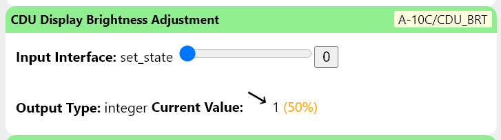
Hi, I'm having a hard time finding the CDU backlight brightness value from the sim. I can only find the rocker-switch which is a simple increase/decrease: I'm currently keeping my own brightness value in memory on the Arduino but it gets desynchronized when the game reloads. Is the actual value from the sim available in DCS-BIOS? Using this for now: // Backlight Control via pin 46, requires a hardware mod to the TFT shield. unsigned int brightness = 255; // The CDU in DCS starts at max brightness, using the same initial value help with synchronization. void onCduBrtChange(unsigned int newValue) { if (newValue == 0) { if (brightness > 25) { brightness -= 25; } else { brightness = 0; } } else if (newValue == 2) { if (brightness < 230) { brightness += 25; } else { brightness = 255; } } analogWrite(46, brightness); } DcsBios::IntegerBuffer cduBrtBuffer(0x10fa, 0x0003, 0, onCduBrtChange);
-
Found them myself, just plain old .dds files in the A10 folder that Photoshop can easily read.
-
Hi, Are the strings coming out of DCS-BIOS documented somewhere? There are some special glyphs for example in the A-10C CDU that i need to map to the correct character in my custom font.
-
Hi, has anyone extracted the fonts from the game? Looking for the A-10C fonts (displays) or any tools to extract them. Thanks.
-
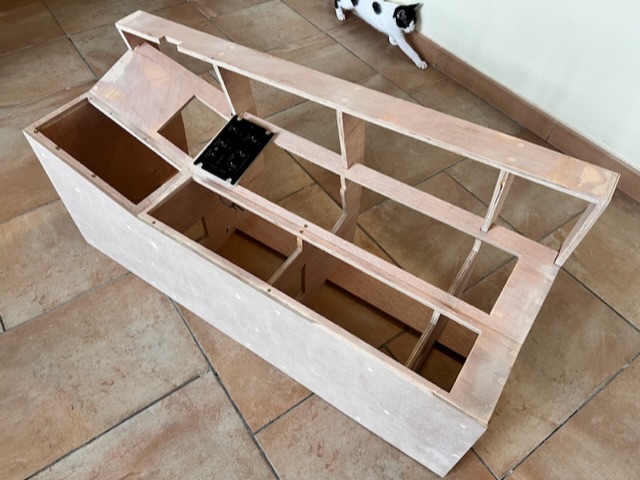
Hi all, I’ve started my A-10C II cockpit build and thought maybe someone is interested in following along. I’m doing some things different (i think), for example custom PCBs and completely modular panels connected with regular network cable. If you want to know more you can find the blog here https://warthogathome.com I’m learning as i go, so if anyone has any input i’ll gladly hear it. Especially around the electronics since that’s what I’m working on now, and I don’t have any formal education on the subject.
-
Any news on this please?
-
Im an idiot, i was using the wrong release. Found it now - thank you.