towsim
-
Posts
658 -
Joined
-
Last visited
Content Type
Profiles
Forums
Events
Everything posted by towsim
-
It's always 'from'.
-
Hi, did somebody ever try to create a pure 'C' DLL extension module to one of the Lua scripts? The examples out of the Lua documentation do not work. All other information I found reminds me on the story of the little girl at the telephone when she was asked 'Is your daddy at home?'. She nodded her head ... Regards Mike
-
Many thanks for the answers. So I can stop this evaluation. Regards Mike What I was just thinking of: What I do not understand is the impact on FPS. If I observe the performance diagram on my computer (3 view channels + 2 MFD monitors) the CPUs idle any what between 7% and 9% while the graphics adapters produces only 5 - 7 FPS. So the bottleneck are the graphics adapters. I would not believe, that the MFDs are made as shader modules. If they reside in the main memory it normally should not eat any performance to exort them to a shared memory.
-
Is this bug in the current A-10 version only? Because I found a lot of threads describing the method with success. Not the best expressed in FPS and color, but at least there was a result. Nevertheless, it helps a lot to know that I was on the right way to nowhere... Thanks and Regards Mike
-
Hi all, since a couple of days I try to export theA-10 MFD textures to a shared memory. function LuaExportStart() LoSetSharedTexture("mfd0") end function LuaExportAfterNextFrame() LoUpdateSharedTexture("mfd0") end function LuaExportStop() LoRemoveSharedTexture("mfd0") end The shared memory seems to be created correctly because I get a valid handle from OpenFileMapping with "mfd0" in my private application. My problem is, that the shared memory, returned by MapViewOfFile, is never filled with bit map data. It is only filled with zeros and does not change during the session. Does anybody have experience with exporting the MFDs and knows probably the reason for my problem? Thanks Mike
-
Winds Hi, Under normal circumstances ATC does not use the terms light or heavy for measureable winds. It would not make sense because a light wind for a B747 has a total different meaning to a C172. What you get from ATC (real world): Wind calm The wind speed is below 3 kts and no fact for the aircraft. Example: Wind calm. variable at [n] kts The direction is constantly changing ant the given low average speed. Example: Wind variable at five. [direction degrees] at [n] kts Almost constant winds at given direction and speed. In Europe you may even get the clock reference for fixed wing aircraft like "wind ten O' clock at five" . The pilot has to calculate the effects to his aircraft. Example: wind two five zero at eight [direction degrees] at [n] kts, gusts [x] kts. Usually a strong wind coming from the given direction with peaks in speed at [x] kts. The wind speed is changing rapidly. The pilot has to add the speed of the gusts to the desired approach speed. Example: Wind one seven zero at ten, gusts twenty left/right crosswind at [n] kts This term is used if a wind comes almost perpendicular to the runway direction and is therefore a direct crosswind. If the wind comes with a remarkable strength from a direction between the runway direction and the perpendicular direction, the controller has to consult a crosswind table which gives the resulting speed vector for a perpendicular measurement. The pilot has to decide whether it is acceptable for his type of aircraft. Example: Left crosswind at seven or: Wind one five zero at fifteen, left crosswind component at seven Tail wind at [n] kts The wind comes from the rear. The pilot has to expect a higher ground speed on touchdown than normal. Example: Tailwind at five expect Shear winds at [distance] [cardinal direction] A shear wind cell has to be expected at the given position. In this seldom case the controller could use the term light, moderate or havy. A similar phraseology is used for micro burst cells. This information is given additionally. Example: expect heavy shear winds five miles to the North North West Regards Mike
-
Habe in 'Input and Output' eine Antwort hinterlegt. Gruß, Mike
-
Hi, I got in touch with SimKits a couple of years ago when I started with pit building. They mainly produce for the Microsoft flight simulator. A driver for the gauges is included and has to be installed. So you can start almost immediately like plug and play. The question is, if Eagle Dynamics products are supported. If you are able to develop your own interface via Export.lua, it would be possible to connect to SimKits gauges in any case. A SimKits SDK is available. The main advantage of SimKits Gauges is their price. A little disadvantage is the material quality. At the time when I bought it, it reminded me on Revell model kits. All plastic and paper. Nevertheless, they did their job. They use internally modified servos used in remote controlled aircraft models. These servos are difficult to control in regard to their actual actuator position. It needs a calibration from time to time. Whereby, it could be possible that they build a technical solution meanwhile. Finally they are focused on civil aircraft models like C172 and comparables. So the variety is limited for military purposes. Regards Mike
-
Using Speed brakes The only advantage of speed brakes is effective speed reduction. There is no other advantage. The primary reason for the device were military needs to fulfill the technical requirements of a war time mission. To have speed brakes available during approach and landing, is an additional safety back up. Fighter aircraft basically follow three types of normal approaches. One is a 360ty overhead (described in the manual) ,a conventional rectangular pattern (seldom) and straight in approaches. All are peace time procedures with the intention to land the aircraft stress free, save and comfortable. The procedures are constructed in a way that you can do your speed management without speedy support. In a 360ty overhead you reduce the speed with a 60 degree bank angle in the break turn. The following base and final is flown as usual. War time procedures are different. The A10 likes to do a so called tactical straight in. It approaches the extended runway centerline at low level. With the final turn (normally between 3 and 6 NM) it does a sudden pop up to an altitude which establishes a 3 degrees glide slope. This reduces the speed to the required approach speed. Even here the final can be flown as usual without speedies. The exceptions are high altitude spiral approaches. The aircraft approaches the field at high level, probably above 10000 ft AGL. Once it reaches the break point it does one or two 360tys to reduce to pattern altitude. In this case the speedies are used extensively. A jet aircraft cannot reduce the speed with the engines others than prop aircraft. They use the wind milling prop blades as air brakes. They can do steep straight in approaches with glide slopes at 15 degrees and more. What I want to explain is, that speedies are not a 'must' procedure during normal approaches. But it is an indication of a thoughtless speed management if they are used without compulsion. Regards Mike
-
Reducing the throttle The throttle is not bound to a distance. You always have a target speed for the specific flight leg you are on at the moment. You have to set the throttle so as to come to and to hold the speed. There exist an advice how to set the engine RPM in a certain situation. This matches only if you are at a speed where fuel weight and payload do not drag you into a dangerous situation. And the resulting speed depends even on flying a Diesel or a GTI. With other words, 'age and maintenance situation'. Once on final you have to consult the speed / weight table. Speed brakes The intention is to use the speed brakes never. If your speed management is well done, you never need to use the speed brakes. So the rule is: If you cannot reduce to, or hold a target speed right in time then you support with the speed brakes. The procedure to use the speed brakes as thrust spare is used for short field landings or at airfields with a dangerous obstacle situation. Flaps Flaps depend finally on the minimum speed and your AOA what you are allowed to fly. A thumb rule is to use takeoff flaps if you reduce below 170 KIAS. The land flaps should be used below 150 KIAS. If you hear the stall warning at slow speed you should think about setting flaps intensively. Idle On a normal stabilized landing with flaps set to land and on a 3 degrees glide slope, you will need a small portion of thrust to hold the Vref (minimum approach speed + 10) until touchdown position. This implies, that idle will be set if you are at touchdown and close enough to the ground that the following stall will not end in a crash. If you are too fast on final, you would use idle and probably speed brakes from the moment you recognize the situation. Landing speed The landing speed (KIAS) depends on your total weight on return. Under normal circumstances a pilot would determine the speed out of a diagram. Even here a thumb rule can be used. 120 KIAS plus 5 kts for every 1000 lbs additional load. Pilots even say 120 KIAS plus 5kts for every children. If gusts are reported, you have to add the gusts speed to your approach speed. Regards Mike
-
Hi Duckling, thanks for the info. I used the link ilikepie posted for me and got a good contact. I was introduced to the LUA export and did my first experiments already. It seems to fulfill my requirements. Nevertheless, I will check PeterPs threads. I am hungry on information. I use IOwarrior and SpinWarrior interfaces. They have a good software library which gives you access to the smallest bit. The hardware I use up to now are original consoles from the F104. It gives me a pretty old time feeling and they are made of old style electronics so that it can be modified easily. Thanks Mike
-
Hi metalnwood, that's exactly what I am looking for. Thank you so far. It is a complete different approach compared to FSX, but seems to be more straight. Regards Mike
-
Hi metalnwood, I am new in this forum and found your work more than interesting. You obviously found out all that what I am looking for. The really interesting part is, that you use an Ethernet interface. That really simplifies the usage. The other is, I observed in your video that you changed the frequency in the simulator and it was displayed on your hardware in parallel. Do you read out the values from the simulator engine? If yes, would you share your knowledge how to do it? Or simply give a push to the right direction ? Regards Mike
-
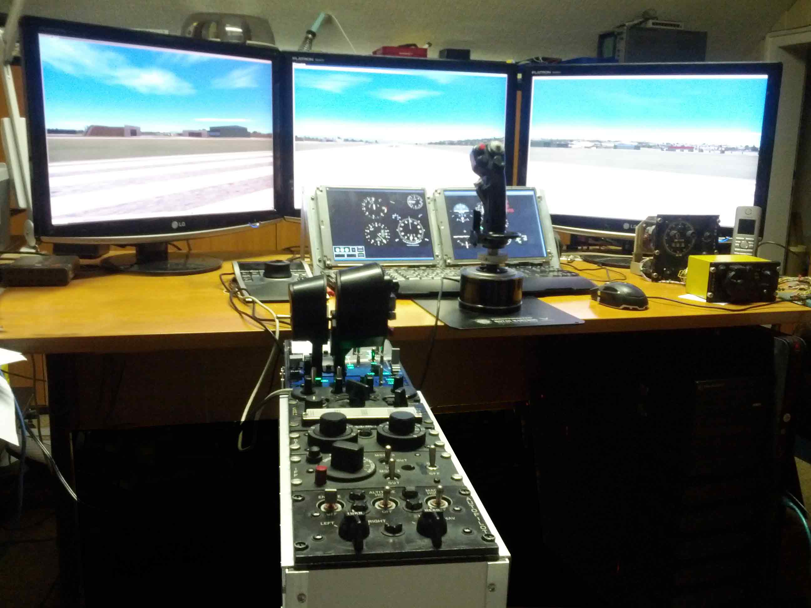
Hi all, I have some basic questions regarding the simulator engine: I have heard some rumors about a SDK. Does someone know where to buy it or if it even exists? In one of the threads, explaining the monitor setups, I noticed, that there are some more views which can be exported. Ís a list of LUA keywords available like CDU_SCREEN, RWR_SCREEN or even a document describing the usage? Meanwhile I am able to control most of the switches and buttons from an external hardware. Does someone know whether it is possible to suck data from the simulator engine like attitude, vector speeds, positions... Are there other people around who are working on hardware extensions. Or is there a specific form for pit builders (see the attachment for a better understanding) ? Regards Mike