hegykc
-
Posts
791 -
Joined
-
Last visited
-
Days Won
4
Content Type
Profiles
Forums
Events
Everything posted by hegykc
-
I can add more holes on the new adjusters there is space for 1 or 2 more actually. But I have the early white pedals and when I use even the first hole on these adjusters, I keep pressing brakes when I try to use rudders because the spring on my white pedals gets too weak. So that's why I didn't add more holes for even weaker spring setup. But I didn't take into account that the new pedals have a stronger spring. I'll start adding more holes to the adjusters right away.
-
Got it. Interesting, now let's see how many need them to be lower and I'll see what can be done about it. The lower the foot rests go, the higher the force needed for braking due to shorter lever. Might have to add an actual weaker spring with the set, we'll see.
-
Thanks for the write up! Take a look at the orientation of the new spring adjusters in the render above. The whole you point in your image is not even supposed to be used (although I will move it away from the wall in the new design). You should put the spring into the FIRST hole (closest to you when they're installed, those 2 lonely extra holes are the ones I added for weakest spring force). Regarding the rough finish. I first tuned and tuned the settings until they were super smooth. And then my foot kept slipping and I had to design some ridges. But then I thought why, just reverse the settings and save time on printing and have them naturally rough so your feet don't slip. Also, you are not suppose to reach both the floor AND top of the pedals. In normal flight your toes should be on the bottom part of the foot rest and only put them on top when you use the brakes. You don't brake with heels on the floor, you have to raise your feet and put them on top of the pedals. Like this:
-
Yeah absolutely. That's why I made the new adjusters, you're not the only one with the problem. Not everyone has the luxury to bolt the rudder pedals down to the floor, and the heavy spring not only rolls the office chair but also lifts the rudder pedals off the floor. Doesn't matter how realistic I want it in my simpit, when there are people who must fly in their office room, or their living room. Gotta have something for everyone.
-
I didn't bother doing spring force simulation, but according to my foot the new adjuster can get the spring force down by 50% maybe. And I could even add 1-2 more holes for even less spring strength. So definitely install them and let me know how much they help. I don't use them personally, because I like everything to feel heavy-duty and realistic. Don't know if you've ever pressed the brakes on a 1970's car, but you might be shocked at how much force you need to apply to stop the vehicle. That's why I made the Damper Mod for even heavier pedal movement feel too.
-
Combat Pedals should start arriving this week to those from EU countries. These combat pedals shoud be angled quite vertically. If you have your MFGs on the floor, not attached to anything, then the brake spring strength might be too high, so you'll have to replace the old brake spring adjusters, with the ones you got in the package along with the Combat Pedals. Milan from MFG has a video on how to remove the pedal mounts easily, then you should proceed to remove the brake spring adjusters, and replace them with the new ones with 2x extra holes for even weaker brake spring strength: ${1} To remove the nuts from the old brake spring adjusters use a trick:
-
All the test pedals are being shipped tomorrow. I have used different settings in manufacturing each set. If yours brake apart, you can report it and I will cross that particular setup as non-working, and re-send you a new sample on my dime. Try out both high and low positions, and also all angles so we can figure out if any modifications are needed to the design.
-
Hi guys. I prototyped these 3d printed combat pedals for MFG Crosswinds. I have tested them myself for strength, hardness, functionality and ease of manufacturing. They pass. Height adjustable +/- 26 mm or 1 inch Designs are for F-16, F-14, F-18 and P-51. Colors Black, Grey, Boeing White and WWII green. (the only difference is the cutouts in the pedals, F-18 has holes, F-14 & F-16 have squares, WWII has no holes) I've sent them out to the 3-4 people that own MFG's in my country for further testing. But I would like at least 20 people to confirm they're ok and are worth making. I'm in Croatia, so if you'd be willing test them out for the price of shipping. Let me know. They use existing bolts so it's a fairly light and small package.
-
I'll be taking more photos this week, with aluminum mounts like the Monstertech ones for desktop use. You can swap handles for a one with twist grip for K14 range axis. There will be videos and first impressions by an online squad of 15 pilots later.
-
I will open a new thread as soon as I photograph and film the modern stuff.
-
I will continue that story in in it's own thread. These are much simpler to produce, test and perfect.
-
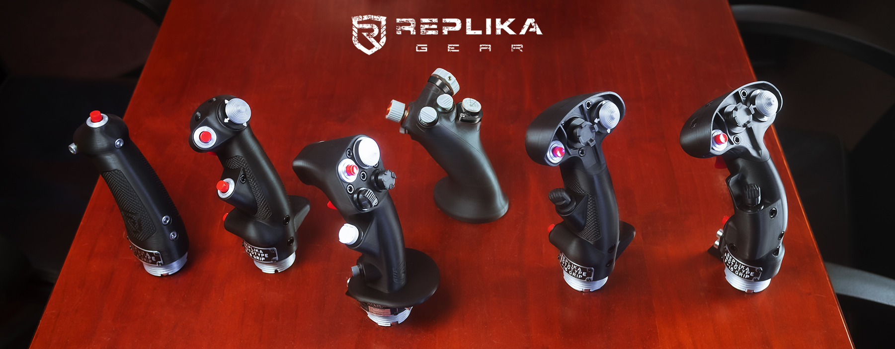
Hi all. Some of you may remember me from my earlier attempts at manufacturing simulation gear with emerging technologies, a few years ago. Unfortunately quality and speed of processes just wasn't quite there for a fast and reliable manufacturing process. But I've been quietly working and pushing boundaries so today, due to a convergence of several new technologies, and becoming available to the average engineer, I am finally able to present some of my finished, functional work that is up to the standards of quality and realism I was hoping to achieve all those years ago. These are 3 prototypes that I have been personally testing for the last 6 months. Electronics are arduino clones, programmed as generic windows joysticks, no drivers, plug'n'play. If you want, you can even program your own firmware. They come with a metal desktop stand, trim boxes, flaps and gear levers, and complete set of switches that are not in these pictures but will be presented soon. Here are the photographs I took in my newly assembled studio. As I get familiar with the camera I will present many more and of course, a youtube video of them in action. Here are the first few photographs: - short usb cables only for photo shoot - everything is designed from purchased WWII blueprint scans - fixed gyro throttle handles on these units, but twist handles are in testing phase These units will go to a local virtual squad of 15 pilots for outside beta testing this month. I will post further updates and videos in this thread. My modern hotas prototypes will have a separate thread soon. Cheers!
-

Open Source Joystick FFB / DIY FFB Joystick
hegykc replied to Berniyh's topic in PC Hardware and Related Software
Motors and drivers arrived. I'll be testing it out in the upcoming weeks... -
You will not have to wait a year. Because I cannot afford to delay the sales any longer. My savings I had allocated for this, is running out. The time to start selling is as soon as possible. But I needed electronics in my mechanical designs, and I needed to program them. And that's what the last month or two were spent on. I'm going to show you a"render" but please keep in mind it's a completely developed solution. Schematics, board layout, components and physical dimension checking in my 3d cad software. But you will not have to wait for me to finish these electrial products, because I'll just use off the shelf arduinos for the very first batch of my sales. All my electronic sim products will use interrupt based, event driven programming, unlike the Arduinos, dumb-busy-loops and spaghetti code in use in every hardware built on these forums at the moment. It is free and copy-paste code so I'm not trying to talk down again. I'm just trying to do better. Here is a 40-bit I2C switch/LED driver with interrupt capability. 64 of these bad boys can be connected to 2 - 4 I2C channels on the 120/180 Mhz development board I'll be using, or my own MCU board I'll develop to drive my full simpits. That's a maximum of 10.240 switches or LEDs or any mix of the two. I have the same kind of driver fo analog axis, to drive up to 216 axis. Everything is interrupt driven, meaning none of the 10.000+ switches, or 200+ analog axis are talking to the microcontroller until you put your hand on them and change something. Also all of the 'drivers' are taking on the computing tasks and only sending ready-to-read results to the microcontroller. So not only will my MCU be dozens of times more powerfull then your average arduino, it will have to do dozens of times less work. All of the electronics are also on the same protocol. Meaning you can plug your P-51 throttle into an F-14 engine panel. Or plug up to 4 full simpits on a single microcontroller. Future proof and compatible. *again, you do not have to wait for me to finish these custom eletronics. I'll focus on getting the P-51 and Fw-190/Bf-109 throttles out with arduino electronics. The warthog spring mod and head tracking unit out. That is my No.1 priority as of today. I just had the oportunity to develop these now instead of in 2 years, and I took it. You'll be thanking me later. Save
-
If you don't like this, just don't follow it. No hard feelings. It couldn't be simpler. No one needs rescuing here, no one is getting scammed. And if there's no one rushing me maybe I'll make less mistakes of trying to get something out too soon. Come back when there's something to buy, and you can discuss/criticize/suggest products then, no grudges will be held against you or your money :) In the mean time, I'll keep posting updates on the prototyping progress, for people who want to know the state of the project. Save
-
An excuse is what you offer when you do not complete a job you were tasked with, a chore you were required to do, or pre-orders you took money for and failed to deliver. I have no one to make excuses to, as I do not owe anything to anyone here.
-
Why am I even in the same sentence with these industrial giants ??:D At least compare what I'm trying to do with guys that were on my level once, and whom I look up to. Like SlewDevice, MFG, BRD, MonsterTech... projects that started as a one-man show, or still are. I do understand the skepticism and loss of patience though. But, I never asked for anything, I never took anything from anyone, so I don't owe anyone anything. You have no investments into this, so you shouldn't hold any expectations. Let's just look at this as a slimmer of hope, for us study simmers to have a much richer experience. If you're tired or had enough, it's fine, I understand. Just take a brake. Once these are for sale, I assure you, you'll hear about them. I'm just informing those that are new to this thread, or are still interested in the state of the progress. My plan was to start selling the spring mod in August/September because I had no one to do the custom pcb's needed for the rest of my projects. So I was stuck, and had to move forward with something. But the spring mod is not a product, it's a cheap silly little fix. It won't pay enough, for me to hire someone to handle them, so I'll have to handle the orders my self. And I'll be stuck doing that until the orders dry out, after which I won't be left with a bag of money because the profit it earns will cover the living expenses for the time it takes to fulfill the market needs. The head tracker alone would have been a way better start. Or the replacement grips, or the generic FC3 style panel, or basically anything I had designed it the last year or so. But I didn't have the pcb's covered, nor did I know how to pick electrical components or how to program them. Now, I can personally decide on electrical components and programming, and design custom pcb's for them. Those are the last pieces of the puzzle that fell into place last month. And they were needed for 99% of my projects. I shall now pick 2-3 of my simplest projects to go along with the spring mod. Or just one, like the head tracker/clip. That will make the critical amount of orders, for me to hire a worker or two. Because if I start assembling and shipping myself, due to not reaching a critical amount of orders, forget about a product line up cause that's what I'll be for the next year or two, a worker with a well paid hobby. And if I go with spring mod alone, chances are pretty high for that to happen. With the head tracker/IR clip, not a chance. That goes way beyond study flight sims. That's a general gaming device, 100x the potential customers. And now that I can understand the electrical components, and make my own custom pcb, it opens up a whole new world. My original design was hand soldered wires and separate off-the-shelf battery charging module, again hand soldered to the rest of the electrical mess. That's a minimum of 20 minutes to assemble the unit, after which I have to stuck the whole mess into the casing. Now, it will be the most elegant solution, with everything on a single pcb. A 60 second assembly job. That goes for all the other projects too. And there are no more areas to figure out. This was it, the last one. I can do any kind of plastic/metal fabrication, and design/program the electronics for it. I just can't go assemble and package spring mods myself now, I have to include this. Designing this kind of simple pcb's is a couple days work once you know what you're doing, so it won't be a major delay. Save
-
Both IRled/IRcamera and gyro/accelerometer/compass versions. Save
-
That cdu main board is just a single piece, out of a whole family of arduino compatible electronics intended for full cockpit interface using a single arduino board. 1024 switches, plus 1024 LEDs, plus 1024 servo motors. Well, maybe a separate arduino for servo motors depending on A-10 cockpit tests. The plan is still spring mod asap. But an opportunity presented itself, to fulfill the requirements needed to prototype a working, full A-10 or any other cockpit, including electronics and programming. The requirements I lacked, and was trying to acquire since the very beginning. At the cost of another month or two delay. I took it. At this point, I'm not interested in debating this delay. I'm going to start with more then one product. This is just to inform you, I'm not looking for feedback on my decisions. We waited for 5 years for a fix/expansion form TM, they gave us more plastic crap. If anyone feels the need to whine, call them :) I will now pick 2-3 additional products from my already mechanically designed library, and make the electronics/programming needed for plug'n'play units, to go along with the spring mod. Products that cater to a way larger audience than just people with a warthog. Therefore building myself a much healthier and stable, risk-free foundation for immediate growth. Save
-
Don't be too quick to judge them. After all, they are the only ones making a commercial mid-to-high-end product like that, in quantities. The fact that there is a WWII style joystick, alone, is remarkable to me. Putting an adapter to make grips from a competitor compatible is fixing their mistakes. I'm sure they'd like to keep the option of their own grips open. I'm certain they had plenty of good reasons for this. I do fell for your disappointment and false hopes, though.
-
Alright. moving forward :) I'll have something to share soon too: This was the first variation, now it's a backup. The new one has only one i2c chip and matrix for the keyboard. It's a fully developed and ready-to-order schematic, not just a render: Save
-
Open Source Joystick FFB / DIY FFB Joystick
hegykc replied to Berniyh's topic in PC Hardware and Related Software
Ok, everything ordered. Once I test which mechanical components work and which don't, I'll order multiple motors and drivers, make a few testing rigs and send one to you and anyone else interested in developing this. As a side thought, wouldn't something like this be easy to interface with the sim through DCS-bios? It can drive a dc motor instrument so why not FFB. I guess with limited "hand written" effects though. Like basic force loading: motor_X_torque=true_airspeed motor_Y_torque=true_airspeed*2 (make elevator twice as strong) Stick shaker: if true_airspeed=stall_speed execute a quick left-right sweep for both motors Gun trigger: if gun_trigger=on execute a quick left-right sweep for both motors (stronger or weaker then stick shaker sketch, and this can even be programmed to specific rate of fire /strength for cannons and machine guns) -
Open Source Joystick FFB / DIY FFB Joystick
hegykc replied to Berniyh's topic in PC Hardware and Related Software
Hey those bigger brushless DC motors are 36V/7A, so the small 2A L298 drivers wont work. I'll have to go with these 36V/15A dual drivers: http://www.ebay.com/itm/3-36V-Dual-15A-H-Bridge-DC-Motor-Driver-30A-for-Robot-Car-Arduino-Compatible-/111140003697?hash=item19e075df71:g:cMEAAOxy-o5R0NqT&autorefresh=true Does that change anything sketch wise? (the other smaller brushed motor will work with small L298 driver) -
Open Source Joystick FFB / DIY FFB Joystick
hegykc replied to Berniyh's topic in PC Hardware and Related Software
This kind of basic testing setup would be very helpful in mechanical design, so whatever I need to do, or learn to do I'll do it. You don't even have to waste your time explaining the details, just point me to the right direction. 1) Is this what I need for atmega isp programming?: http://www.ebay.com/itm/51-AVR-Atmega-Programmer-ISP-Downloader-USB-ASP-Downloader-/201066541625?hash=item2ed07ff239:g:mA4AAOSwjVVV1pX~ or http://www.ebay.com/itm/STK500-AVR-ISP-USB-Programmer-Spport-WIN7-AVR-STUDIO-5-ATMEL-ATMEGA-AVRISP-/140852662670?hash=item20cb79118e:g:AgMAAMXQWlFRw4yu and I have arduino Uno's ATmega328P, Arduino Micoro's ATmega32U4, Arduino Mega's ATmega2560 and Arduino Due's Atmel SAM3X8E ARM Cortex-M3 on hand. But if I need something else or a programmer you just say so, I'll order one. 2) I have a teensy 2.0++. For that, I should just consult their website? What would you suggest, 1 or 2? -
Open Source Joystick FFB / DIY FFB Joystick
hegykc replied to Berniyh's topic in PC Hardware and Related Software
So this would test the motor stalling torque at max power/speed. How is force loading done. This kind of low level arduino code is withing my abilities right now. I can further modifiy the sketches myself. How about we make the test a little more complex by breaking it into basic FFB effects. Like a "stick shaker" sketch. Like the one you posted with delay, plus speed/power paramaters. And a "force loading" sketch. Something to test the effect of wind speed on control surfaces? A sketch that would increase force loading from min to max with a delay. The effect that wants to return the stick to neutral. And what ever other effect we can test without actually connecting to the sim. I could tell right away which mechanical parts work and which don't.
