Combat2468
-
Posts
45 -
Joined
-
Last visited
Content Type
Profiles
Forums
Events
Everything posted by Combat2468
-
Can double me up as well DM if it helps out.
-

LIlliput UM80 monitors and TH MFD's
Combat2468 replied to jdmesty's topic in PC Hardware and Related Software
Really good tutorial on YouTube for doing this type of setup. http://www.youtube.com/watch?v=GHU8iQ-jh5Y -
Arduino, EOS and other funky ways to interface
Combat2468 replied to agrasyuk's topic in PC Hardware and Related Software
Erm, now i'm getting worried. I've bought a couple of GP-Wiz40's thinking it will only need 2 of these per side for the panals but no mention in here yet. Am I on the right track or are they not up to the job? -
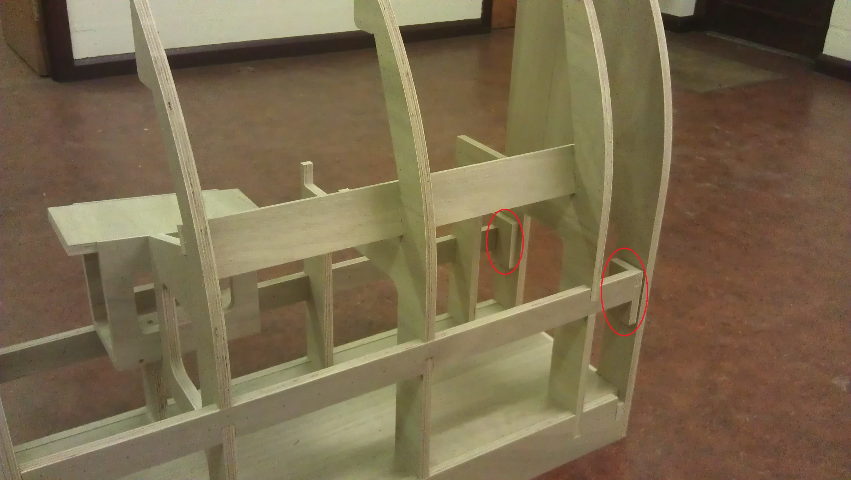
Thanks for all the encouragement guys. Jase: Yep, the instrument panal is going to be a 23" 1920x1080 monitor to start, using helios. I'm watching a thread of hegykc's in anticipation, he's looking at making all the dials, http://forums.eagle.ru/showthread.php?t=100076 and even posibly to sell. But looking more near the end of the year for that. I've had a lot of PM's from UK based members asking where I got the designs cut and for how much. The company is called CUTCNC www.cutcnc.co.uk based in Uxbridge and cost me £564 for materials, cutting and delivery inc VAT. Thats for the left and right sides, base and front sides. dont be surprised tho if they quote you a bit more as I think they knocked off some of the delivery charge after I said it was for an Air Cadet project. Not 100% on the rules here so just incase, I have no afiliation to this company or any employee, so not attempting to advertise just help others in this forum. Not much more visually on the build, just a load of screw heads. Did come across a couple anomolys. In the first pic highlighted are 2 brackets to attach the back plate to the side pods, these have been pilot drilled but the back plate hasn't. Double checked the .dxf and not in the design. Nothing a G clamp and pencil couldnt sort out. Next one a think is down to the workshops where i got it cut. The bottom plate for the throttle mount sits on top of one of a ribs so needs to be routered out but mine wasnt. Might be worth pointing out to them if going to the same place. luckly I had a hammer and chisel with me.

-
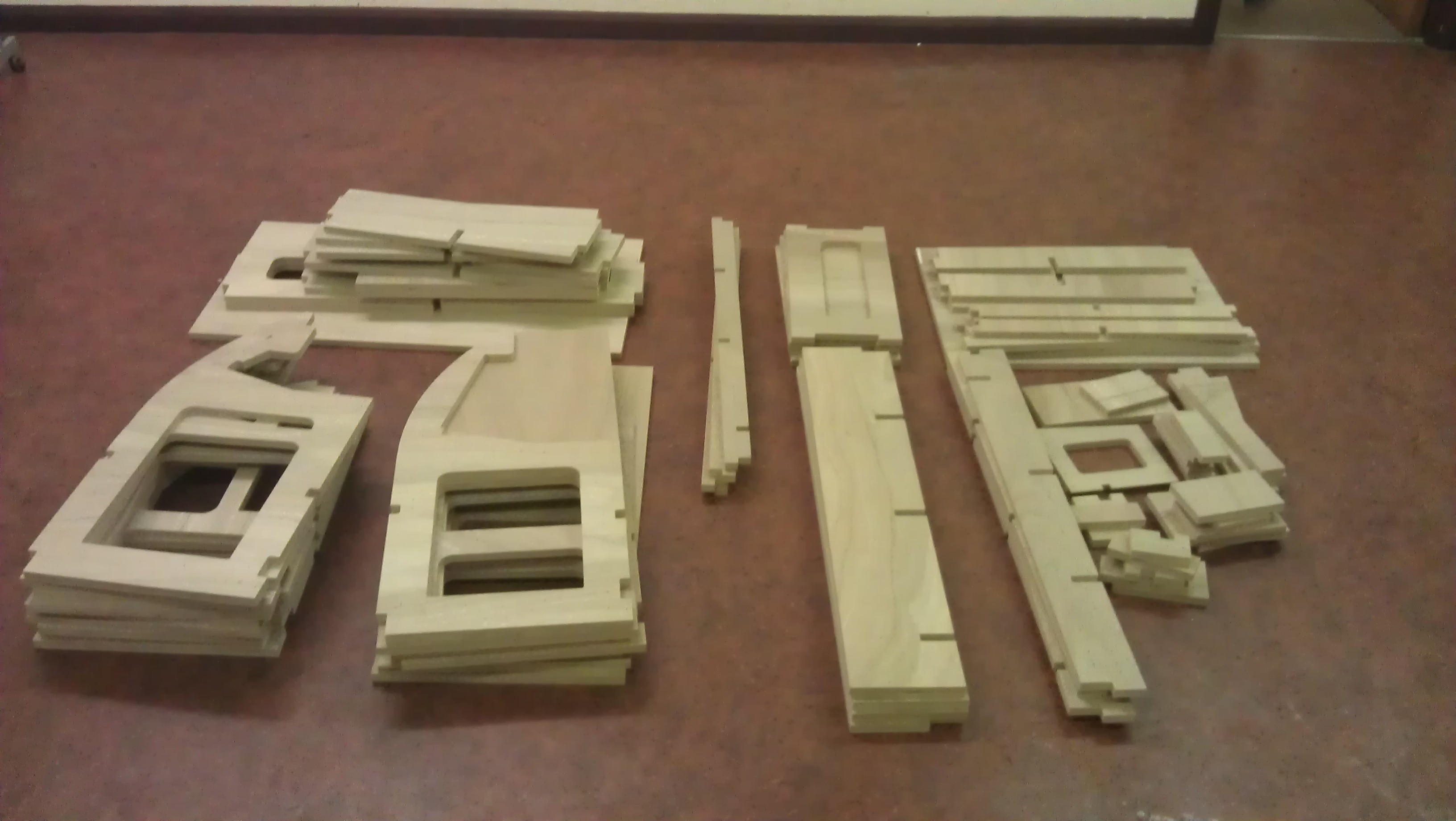
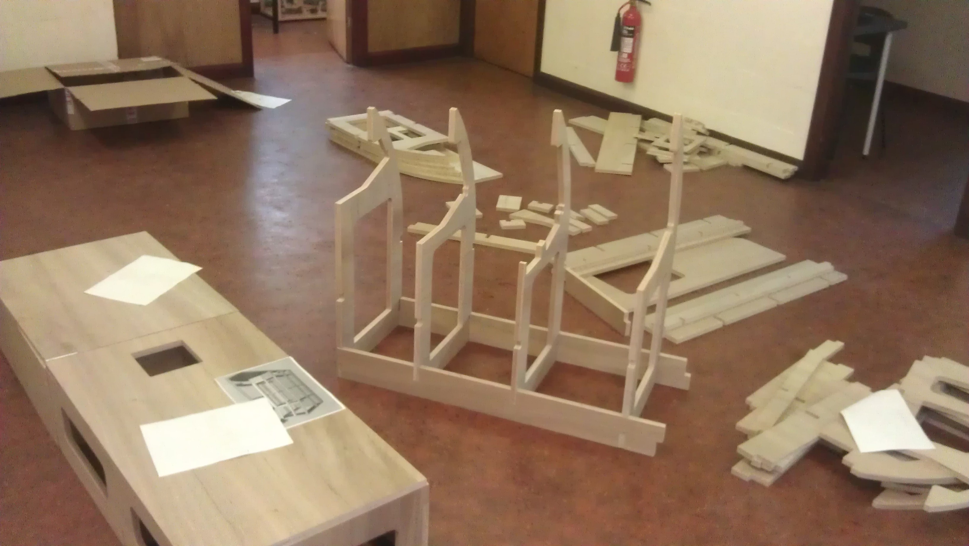
Well, a month of looking in amazment at threads from Y2kiah,Gadroc,Deadman and agrasyuk to name but a few. Then a month of getting involved with the forum and now here I am with my first thread and it's a striaght into a pit build, thanks guys my bank manager hates you all:lol: But I love you. :thumbup: A bit of background stuff, I'm a retired RAF Armourer so good with a hammer. Now in laptop repair and refurbishment (electronics good, programming bad) so looking at the easyest solutions with panal intergration (Thank Gadroc for Helios). The build is actually for an Air Cadet Sqn that i'm an instructor at and will be getting them involved in the work, Many hands make light work. Which will be needed as have to get it to a minimal working simulator before the end of Febuary. The pit uses Y2kiah's shell, big thanks to him for publishing all his work, and a lot of inspiration taken from the guys above. I've got a few of my own ideas mainly around the seat and electrics area that I hope to implement aswell and maybe inspire others. And on with the build, sent the .dxf to be cut last week and arrived on wednesday. Took a bit longer as the workshop emailed me with some questions about the cutting, since i'm completly CAD iliterate at the moment had to post for help and I think it was Linden that came up with the answer. For anyone in the UK who are looking at doing this if you include the below instructions and it should save some time in emails. "All module layouts are designed for a 4'x8' sheet of 3/4" nominal plywood (.703 actual) and .005" spacing. Using a 1/8" bit for drilling, and up to 1/4" bit for cutting, .02" tolerance on the notches. The drawings are in imperial measure, and so need to specify inches during import. Also the screen grab which outlines three pieces is for a plunge cut 0.5" deep." We spent today preping, to screw it together tommorow, cutting right angles into the slot cuts and then testing the fit. This is due to router bits being round and so the corners in the slots are round too after the workshop, and as such the parts dont quite fit flush until their made square. Think we got a bit carried away:doh:
-
Thanks Tom, Forgot to say set 2 for me please.
-
+1
-
Yep, The raw files on post #295 no mods. Will be starting my own build thread the first weekend after i get the parts, should give you an idea of what you'd be buying.
-
Cheers Tom, +1 for the next run, Anymore? he needs minimum five for a viable run.
-
Hey JaseGill, Cheapest quote I got was from these guys www.cutcnc.co.uk, they are based in Uxbridge but can deliver. The price i'm paying is £564.96 all in, but think i got a bit knocked off as it's for an Air Cadet project. That was for 4 sheets of 8x4 Ply, cutting and delivery. I'm not building the nose extension due to space so the cuts were for Left Side Panel, Right Side Panel, Base and Front sides. Was original going to be 5 working days but forgot to put in some of y2kiah's instructions so had a couple days emailing. If you do go with them just let them know the below. The drawings are in imperial measure, and so need to specify inches during import. Also the screen grab which outlines a couple of pieces is for a dado/pocket cut 0.5" deep. The cheapest after these was a place in shefield, £700+ for MDF and £1000+ for Ply. Hope this helps.
-
Yep, spot on linden. Thanks for that, should be building come the weekend:)
-
HELP! Have finally taken the plunge and decided to build but come to my first stumbling block. I've sent off the .dxf files to my workshops (thanks y2kiah) with the instructions as posted 4x8 ply etc, and have got this reply "Your drawings have come in really small. We are able to scale them back up but require a reference to scale them up to. So are you able to put a boarder of 2440 x 1220mm around each drawing or give us overall dimensions of a piece for reference?" Does anybody know what they are asking for. I'm an old school armourer who uses hammers and crowbars, and this computer design thing is beyond me. Can anyone help please.
-
Glad to be of help :idea:
-
Thrustmaster Warthog Screw measurements
Combat2468 replied to Cowboy10uk's topic in PC Hardware and Related Software
Drawings for both base plates are on the thrustmaster website. http://ts.thrustmaster.com/download/accessories/pc/hotas/manual/HOTAS_Warthog/HotasWarthog_Plates.rar or if i've done this right, the .pdf should be attached. Says the holes themselves are 4.5mm dia and are positioned 60.1mm horisontally and vertically appart. HotasWarrhog_Stick_Plate.pdf HotasWarthog_Throttle_Plate.pdf -
Epic:thumbup: Are you using 3 projectors or 1 with warping software?
-
Try right clicking the .exe file and run as administrator. Might not be set to auto activate the user account control feature.
-
Forgot to add, can pay straight away.
-
Hi agrasyuk, Really interested in buying this but cant seem to send you a PM. How much total with shipping to the UK? Regards