FSFIan
-
Posts
1301 -
Joined
-
Last visited
-
Days Won
7
Content Type
Profiles
Forums
Events
Everything posted by FSFIan
-
On the hunt for a cougar handle pcb
FSFIan replied to trigen's topic in PC Hardware and Related Software
I can't find a datasheet on the CD4021CM, but any CD4021 that has the same package and can handle the supply voltage used by the board should work. Every CD4021 implements the same logic. Differences would be things like the supply voltage range it can handle (take a look at the datasheet, but both 3.3V and 5V are commonly supported), the maximum frequency it can handle (you don't know how fast your board is shifting the bits out, but maybe you can determine an upper bound e.g. based on the clock frequency that the microcontroller runs at -- or just don't think about it, any CD4021 you can find will probably be fast enough, and if it is not, it won't break anything else) and the temperature range it can operate under (not critical here, the standard consumer temperature range of 0 to 55°C is enough). -
A 3D view for the DCS: World 1.5 Open Beta Mission Editor
FSFIan replied to FSFIan's topic in Mission Editor
I think it should. If it does not, let me know and I will take a look. -
On the hunt for a cougar handle pcb
FSFIan replied to trigen's topic in PC Hardware and Related Software
I think the most likely culprit is a fried (part of a) shift register, especially if the board got an electric shock from static discharge. Maybe one of the ESD protection diodes on that specific input pin failed short. My advice would be to replace the shift registers and see if the rest of the board is ok. Shouldn't be too hard if you can find someone who has a soldering iron and a little experience using it, although a hot air station might also be a big help with desoldering the old chip. Check if there is a "Repair Cafe" or a hacker/makerspace near you (or find another convenient source of electronics nerds, maybe you already know some). Because it is easier to do, try replacing the switch first (or just desolder it and see if the button is no longer stuck -- I assume those are normally-open switches). If one of the buttons has a problem but all of the other ones are OK, you have pretty much ruled out a failure in the main PCB, because the state of all the working buttons is sent over the exact same wires and processed by the same microprocessor. -
[ANN] Web-based Lua debug console for DCS: World missions
FSFIan replied to FSFIan's topic in Mission Editor
It probably fails to work with the new mission file format. I never tested the Witchcraft unit move functionality with 1.5 or later. Try this thing instead. -
Gigabit Ethernet uses all eight pins. If you only have four pins, you can only do Fast Ethernet (100 Mbps). Any properly designed network device should not break if you plug this cable in. Ethernet ports in end devices have coupling transformers that won't pass direct current, and any properly designed ethernet port will have protection against transient events as well (e.g. a lightning strike in the vicinity of the network cable or an electrostatic discharge).
-
In an earlier revision of my board, I had jumpers labelled PASS_5V and PASS_12V to disconnect the 5V and/or 12V lines from the second RJ-45 connector, so you could feed power to individual segments of the bus. I took them out because the PCB routing didn't work out (too many traces in a small space, and I didn't want to make the board wider than the Arduino Nano to keep it breadboard-compatible). Wikipedia claims that one conductor in a Cat5 cable can safely carry up to 360 mA. In a real cockpit build, there will be single panels that need more than that (LED indicators, backlighting, steppers...). I expect that most finished panels will be powered separately. Supplying power via the Cat5 cable could work for a few boards that have mostly inputs (switches, rotaty encoders, etc) instead of power-consuming outputs (LEDs, steppers, ...) and don't have a backlight, or for powering a single board during development. @BravoYankee4: Try plugging your specifications into http://pcbshopper.com/. According to that website, you can get a lower price from Smart Prototyping, and the shipping time to Sweden is a week less than ITEAD Studio. Also, what software did you use to design your board? Just curious.
-
I did some more reading and decided against selling boards. I would have to deal with CE marking and RoHS compliance, which is simply impossible to do without lots of cash and a bunch of lawyers. There are some claims on the internet that development or evaluation boards are exempt, but I could find no mention of that anywhere in the actual legislation. The most informative source I could find was a .doc file hosted on element14.com (second Google hit for "RoHS development board"). In a nutshell, any sale of a dev board in Europe without CE marking and RoHS compliance documents is/was illegal, but so far, no authority has bothered to do anything about it. I know that it would be very unlikely that I would get into legal trouble over this, but I also know that if I did, that would probably mean a hefty fine at least, and unlike the big corporations that have sold dev boards in the past without bothering with RoHS or CE compliance, I don't have a legal department. Instead of selling boards, I plan to publish the board design (well, I was going to do that anyway) and where I sourced my parts once I have something working. I will then fill out the necessary paperwork to tell the German IRS equivalent that I am a freelance software developer, which will enable me to set up a donation button. If people want to help me expand the number of devices I have to test, they will be able to do it that way. You see, any income you have that isn't already reported by e.g. your employer needs to be totaled up and written into a box on your tax return. It does not make any difference in the amount of tax I need to pay, because the authorities will subsequently ignore it as it will be way below any applicable amount of exemption. But failing to do this would count as tax evasion, even if it would mean less work for all parties involved and yield the same results :doh:
-
I have attached a preview of my first stab at an RS-485 breakout board to this post. I have ordered parts to populate ten of these from AliExpress, which will probably arrive in about four weeks. The RJ-45 sockets will not be the 90° type shown in the picture but a "straight through" type so you'd plug in the cable from the top instead of the side. Since there is no datasheet for the sockets I ordered, it remains to be seen whether they will actually fit the boards, but AliExpress seems to be the way to go if you don't want your connectors to cost more than the microcontroller board they connect to. I still don't plan to build a pit of my own, but I need a more convenient and more permanent test setup for DCS-BIOS development. A setup based on Cat5 cable also makes it easy to experiment with different RS-485 bus lengths. The board will have stackable headers, so it is designed to plug into another board or breadboard and have an Arduino Nano plugged in on top of it. The dimensions are about 100x18 mm, with four 3mm mounting holes. I use the following pin mapping for the Cat5 cable: 1 -- A (RS-485 Bus) 2 -- B (RS-485 Bus) 3 -- 5V 4 -- GND 5 -- 12V 6 -- GND 7 -- user-defined 8 -- user-defined The user-defined pair is accessible on the pin header on the right. You can connect the Arduino to the 5V or 12V line on the Cat5 cable by setting one of the PWR_5V or PWR_12V jumpers, or clear both jumpers and power it externally The RX and TX jumpers can be used to disconnect the RX and TX lines going to the MAX487 chip, so you can reflash the Arduino without unplugging it from the board. I consider the thing feature-complete at this point, but the boards will ship faster than the other components will, so I'll wait a few days before ordering the PCBs. In the meantime, I wanted to throw this out here in case any of you have feedback from the perspective of someone who is actually building panels. If there is any interest, I am considering to sell these for about 10 Euro a piece (fully populated including a Nano) once I am happy with the design. That might allow me to eventually get up to an inventory of about 60 boards to test the RS-485 bus with a workload that might be found in a complete simpit.

-
There is no logging functionality built into DCS-BIOS for that. The live view in the interactive control reference has been all I needed. It's simple enough to write an application that connects to DCS-BIOS and logs things, though. In fact, the "test.py" in my python DCS-BIOS example already does this -- it prints the CMSP display lines and the CMSP mode to stdout whenever they change. Add a timestamp to the output and redirect it to a file and you have a logging application.
-
The impedance of a cable depends on how it is constructed. Cat5 cable is specified to have an impedance of 100 ohm. A while ago I read everything I could find and understand about termination and fail-safe resistors. The most informative (to me) resources I could find were these: This article: Designing RS-485 circuits TI app note slyt324: RS-485: Passive fail-safe for an idle bus (no link to avoid auto-embedding, just google "slyt324") I made a simple calculator in JavaScript to play with the equations from the second link: http://dcs-bios.a10c.de/rs485-resistors.html My recommendation would be to not bother with termination unless you have problems with lots of interference. Here is a quote from the first link, from the "Simplified low-power link" section: According to the MAX487 datasheet, the slew-rate limiting feature guarantees a minimum rise time of 250 nanoseconds. That would allow a bus length of up to 12.49 meters without termination or biasing resistors. TI app note slla036d gives a slightly different rule under section 2.1, which works out to a length of 10 meters. My recommendation would be to simply not bother with termination as long as your bus length does not approach 10 m and you are using the MAX487. You can always add it later. Note: I am not an electrical engineer and I don't have any practical experience with RS-485 beyond 20 centimeter long buses on a breadboard, so take everything I say here with a grain of salt.
-
The F-15C is a FC3 aircraft, so you won't find separate indicator files. Try exporting LEFT_MFCD and RIGHT_MFCD and see what you get.
-
Regarding parameter passing: any function that does something slightly complex should use a parameter table. I didn't do that in DCS-BIOS and now regret it alot (I am so looking forward to throwing certain parts of that code away when I get to build v2.0). Parameter tables allow a lot more flexibility with adding optional parameters in the future and make the calling code easier to read when dealing with more than one or two parameters of the same data type (no more "which order were those supposed to be in again?"). The problem of misspelling parameter table keys can be solved by validating them in the function itself. It's even more important in a library like MiST, where you don't have the option of changing the API and fixing all places where it is used at the same time. By the way GitHub has a well-documented REST API, so releases are easy to automate using the scripting language of your choice. For DCS-BIOS, I have a Python script to create a new release -- compile the documentation with AsciiDoctor, bundle it up in a .zip file, create the release draft on GitHub, attach .zip file, open the draft in Chrome so I can add release notes, and upload the new documentation to the website.
-
Steam ist eine Plattform für den digitalen Vertrieb von Spielen. Wurde so weit ich weiß damals von Valve für die Half Life-Serie eingeführt und ist mittlerweile die größte ihrer Art. Ist auch die einzige, die ich freiwillig nutze, da Valve im Privatbesitz ist und erfolgreich genug ist, dass ich davon ausgehen kann, dass die Server auch in 50 Jahren noch in Betrieb sind. Ich finds zwar nicht gut, dass die erfahren, wann ich wie lange welches Spiel spiele, aber wenn es DRM sein muss, dann bitte das von Steam. Man kann auch Backups seiner Spiele machen, so dass man nach einer Neuinstallation nicht alles wieder runterladen muss (oder noch besser: Steam-Library auf zweiter Partition anlegen, dann muss man nach einer Windows-Neuinstallation die nur wieder anlegen und die Spiele sind sofort wieder installiert). Es gibt auch einen Offline-Modus, d.h. nach dem man für die Installation einmal online war braucht man keine Internetverbindung zum Spielen (es sei denn das jeweilige Spiel macht da explizit eine Ausnahme). Faustregel für Steam: wenn du ein Spiel nicht unbedingt sofort haben musst, warte bis es mindestens 50% runtergesetzt ist. DCS: World benutze ich allerdings nicht in der Steam-Version, da ich meine Module direkt bei ED kaufe.
-
Why not have the best of both worlds? Keep only one "mist.lua" in the repository. Attach an appropriately-named copy of the file to each GitHub release. That also gives people a direct link to download just the .lua file (without having to right-click the "raw" button on GitHub and selecting "Save As").
-
Issue with A-10C altimeter display using DCS-BIOS
FSFIan replied to Adrian_gc's topic in Home Cockpits
Hint: use tags for source code, makes it a lot easier to read by using a monospace font and also disables smileys. Can't view the video, but I assume what happens here is that in flight, the receive buffer fills up while you are writing to the display, which leads to incoming data being dropped on the floor, confusing the protocol parser, and ending up with garbage on the display. It does not happen on the ground because the receive buffer is large enough to handle the smaller amount of data that is being sent (in the air, a lot more values are changing all the time). Try using the Arduino Library in the new rs485 branch on GitHub. See [url= http://forums.eagle.ru/showpost.php?p=2636130&postcount=194]this post[/url] for more information. You can download that as a .zip archive here: [url]https://github.com/dcs-bios/dcs-bios-arduino-library/archive/rs485.zip[/url] You will have to change the baud rate in connect-serial-port.cmd to 250000, that's the new standard. The new interrupt-based communication handling is designed to solve this exact problem (only works on ATMega328-based controllers at the moment). I'll try to edit a code example into this post later. EDIT: with the new library, you could try this code: [code] // tell DCS-BIOS we want interrupt-based serial comms. How to do this will probably change in the future. #define DCSBIOS_IRQ_SERIAL #include <DcsBios.h> #include <Servo.h> #include <SPI.h> #include <Wire.h> #include <Adafruit_GFX.h> #include <Adafruit_SSD1306.h> #define OLED_MOSI 9 #define OLED_CLK 10 #define OLED_DC 11 #define OLED_CS 12 #define OLED_RESET 13 Adafruit_SSD1306 display(OLED_MOSI, OLED_CLK, OLED_DC, OLED_RESET, OLED_CS); #if (SSD1306_LCDHEIGHT != 32) #error("Height incorrect, please fix Adafruit_SSD1306.h!"); #endif char* displayString = "---00"; // onDcsBiosWrite does not exist anymore, use Int16Buffers instead DcsBios::Int16Buffer alt10000ftCounter(0x1080); DcsBios::Int16Buffer alt1000ftCounter(0x1082); DcsBios::Int16Buffer alt100ftCounter(0x1084); void setup() { display.begin(SSD1306_SWITCHCAPVCC, 0x3C); display.clearDisplay(); DcsBios::setup(); } void loop() { DcsBios::loop(); if (alt10000ftCounter.hasUpdatedData()) { displayString[0] = mapeo(alt10000ftCounter.getData()); } if (alt1000ftCounter.hasUpdatedData()) { displayString[1] = mapeo(alt1000ftCounter.getData()); } if (alt100ftCounter.hasUpdatedData()) { displayString[2] = mapeo(alt100ftCounter.getData()); } display.clearDisplay(); display.setTextSize(3); display.setTextColor(WHITE); display.setCursor(30,5); display.print(displayString); display.display(); delay (75); } char mapeo(unsigned int valor){ if (valor < 6553) { return '0'; } if (valor < 13107) { return '1'; } if (valor < 19660) { return '2'; } if (valor < 26214) { return '3'; } if (valor < 32767) { return '4'; } if (valor < 39321) { return '5'; } if (valor < 45874) { return '6'; } if (valor < 52428) { return '7'; } if (valor < 58981) { return '8'; } return '9' ; } -
It's designed to work with their SIOC software, which I don't know very much about. Your best bet to make this work with DCS is probably to start with this thread. The only way to make this work with DCS-BIOS would be to rip out all the control electronics and replace them with Arduinos, but if you do that you can probably build your own panel for the same price.
-
FYI: A6 and A7 cannot be used as digital I/O pins, they are analog input only. This has caused a lot of confusion for WarHog and me in the past before we finally took a closer look at the Arduino pin mapping and the ATMega328 datasheet :) A0 through A5 can also be used as a digital I/O pin like you'd expect.
-
Not quite. It's just a way for multiple Arduinos to communicate. (Also, it's RS-485, not 845). Yes.
-
You can use Pin 13 for the TX_ENABLE signal. The built-in LED will turn on whenever the TX_ENABLE signal is on, so you should get an activity indicator as a bonus. The only problem I see is that the LED (and thus the TX_ENABLE signal) will turn on briefly when the Arduino is powered on, which would cause the RS-485 transceiver to drive the bus and disrupt any other communication. It's not ideal, but should not have any long-term ill effects; the software should recover from this (the RS-485 state machine resets whenever there has been nothing happening on the bus for 500 microseconds) and the internal current limiting and short-circuit protection in the MAX487 should prevent any physical damage. In other words: test on a breadboard first, but if it works, you should be fine.
-
That's exactly what I am doing. Any code that doesn't disable interrupts for too long (which the LiquidCrystal library and analogRead() don't do at all AFAIK) won't interfere with RS-485 communication. I have successfully tested with a 16x2 LCD showing the CMSP, the pin 13 LED hooked up to a random indicator light and a push button mapped to the signal lamp test button. I also added a delay(1000) to the loop() function for testing purposes, and the setup still worked correctly (with a lot of lag of course). The new implementation of StringBuffer uses double buffering, so even driving a 320x240 TFT with an ATMega328 to display the CDU should work correctly, albeit slowly. The list of ExportStreamListeners is kept in sorted order now, so the amortized complexity (I might be misusing that word here -- I learned about this stuff over two years ago) of traversing that list during one data update is reduced from quadratic to linear. The new receive buffer only has to compensate for the time spent traversing that list once and storing a copy of the data if an ExportStreamListener is interested. Processing that data (i.e. emptying the receive buffer) is also prioritized over the main program, but it is still done with interrupts enabled, so it can be interrupted by other things (e.g. the timer interrupt to increment the counter behind Arduino's millis() and micros(), or storing another received byte in the buffer). Here's the list of priorities from most important to least important: - RS-485 communication, other interrupts (stock Arduino timer interrupt) - parsing incoming data from DCS and storing the bits that are interesting to this panel - everything else is called from loop(): reacting to data that has changed (changing GPIO pins, writing to displays, etc), checking to see if any switch or other input has changed and preparing a message to DCS I still have no idea how many ExportStreamListeners are too much (although we can certainly handle a lot more than before). Without having any data to back this up, I'd say you are probably fine on a Pro Mini with its ~17 usable GPIO pins. You might be able to break it if you max out a Mega with outputs only, and it's likely going to break if you throw in enough I/O expanders or shift registers.
-
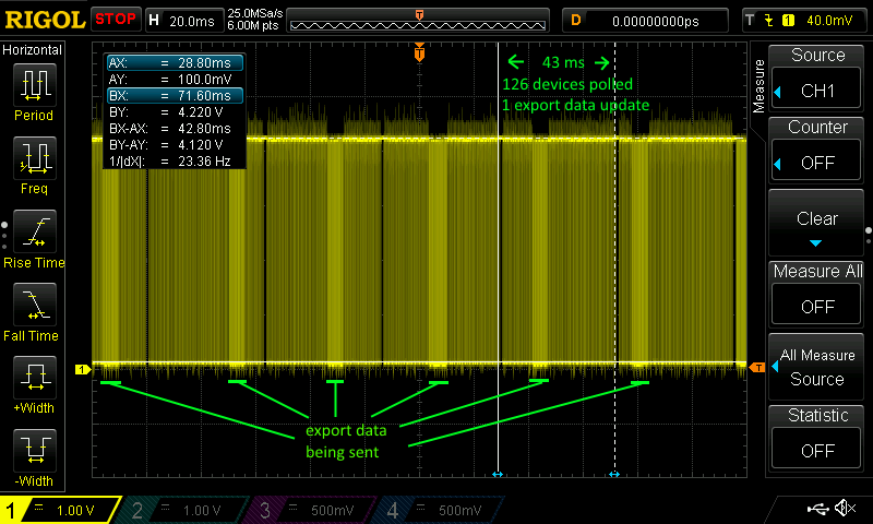
Yes, it's a perfect dummy load. It's the absolute best case. But IMO it has enough reserves to work under more realistic conditions. If it's enough to poll a device 10 times a second instead of 20, the 43 millisecond span I marked in the screenshot is allowed to expand to 100 ms. That's enough extra time to transmit about 1400 bytes (not accounting for delays in between, so let's halve that to 700), which should be plenty for any messages the panels want to send. If that's not enough, the maximum message size can be reduced to less than 10 bytes by switching to a binary export protocol, although I'd like to defer that to DCS-BIOS 2.0 where I want to change a bunch of other design decisions at the same time. My biggest assumption here is that a panel will stay quiet on the RS-485 bus as long as the pilot doesn't touch it, and that the pilot will have at least one hand on the throttle and stick at all times (I know I do), so two panels wanting to send data at the same time is the exception rather than the rule. Otherwise it wouldn't make sense to connect more than one RS-485 bus to one serial connection to the PC running at the same speed. You allow for a 2 millisecond timeout waiting for a response for each poll. That's way too pessimistic. The only way the "reaction time" of a board is going to increase is when interrupts are blocked for too long. And that won't happen longer than about 40 microseconds (the time it takes to transmit one character at 250000 bps), otherwise you are missing RX bytes and have bigger problems. The number of devices is also unrealistically large at 126. Let's assume the Mega supports two buses, and we need 100 devices for the simpit (I think you estimated a total of 60 once), then 50 devices per bus sounds more realistic and can still support a full simpit. You can also design some slave devices as "output only", then they won't need an address on the bus, because all they do is listen. I have seen three buses (with one device each) work, but the timing looks uncomfortably close on a logic analyzer, so it wouldn't surprise me to see that have intermittent issues in real-world operation. All that said, I don't have any real-world data. I don't even have a pit :music_whistling: I am curious to see what problems this will develop under realistic conditions, but still remain optimistic that we can make a single Mega work. Of course, even if we can't, it's not too big a deal, as splitting a bus up is not too hard. I have started to think about a small production run of RS-485 transceiver shields for Pro Minis, both for the learning experience and to get a proper test platform for DCS-BIOS. I feel that the inability to quickly test any code change (instead having to constantly reassemble and tear down things on a breadboard) was the second-most important reason (after general lack of time) for my failure as a project maintainer to review and merge any pull requests in a timely manner.
-
Would the problem be solved by using a separate include file for each mode (e.g. DcsBiosRS485Slave.h, DcsBiosRS485Master.h, DcsBiosDefaultSerial.h, DcsBiosIRQSerial.h) and using global variables or global inline functions in the DcsBios namespace to tell the library about the slave address and TX pins? Did they fix serialEvent so it is acually called from an ISR? I have attached a scope screenshot of 126 devices being polled (well, one device programmed to react to addresses 1 through 126). This shows that as long as the typical case is that no device has anything to say (yeah, I know I have to fix potentiometers to get there), we should be able to do about 20 polls a second for 126 devices on a bus.
-
Great schematic! Note that it's not a question of two or three slave devices but of two or three RS-485 buses. You can connect 32 "unit loads" to each bus. Each transceiver chip is one unit load, so that means 31 slave devices and one transceiver for the master on each bus. There are also transceiver chips that have less than one unit load. The MAX487 that I recommended a while ago has 1/4 unit load, so you can connect up to 128 transceivers to one bus. If you use biasing and termination resistors, this will affect the number of allowed devices, but because the MAX487 has slew rate limiting, you can probably get away without it as long as the length of the bus wire stays below about 10 meters. In any case, with the right transceiver, a single Mega acting as a hub should be enough for the whole cockpit, regardless of whether it can support two or three buses.
-
Any value you get out of DCS-BIOS for a clickable cockpit will be based on a cockpit argument which controls some animation in the cockpit 3D model, so this is to be expected. I am still not sure what you mean by "aircraft heading that the HSI follows". If you want the position of the heading bug in degrees, can't you just subtract A-10C/HSI_HDG from A-10C/HSI_HDG_BUG, then divide by 65535 and multiply by 360 to convert to degrees? If you want the course (set by the right knob), you can also look at A-10C/HSI_CC_A and A-10C/HSI_CC_B ("Course Counter A" and "Course Counter B").
-
I think you want A-10C/HSI_HDG: Output Type: integer Address: 0x104c Mask: 0xffff Shift By: 0 Max. Value: 65535 That is the rotation of the HSI compass card.