Pilum
-
Posts
382 -
Joined
-
Last visited
Content Type
Profiles
Forums
Events
Everything posted by Pilum
-
I see you retain your winning personality by resorting to personal attacks when a simple denial would do Kurfurst. Anyway, excuse me if I got you confused with Hummingbird but since you have a history of posting under nics suspecting that you are one and the same is not such a stretch so spare me the indignation please. I doubt you are in a position to make blanket statements on documentation in DCS's inventory Kurfurst. However, given your hubris you probably refer to the documentation you have contributed. In that case I’m sure DCS by now have figured out that this constitutes the absolute top performance outliers on the Me109 and the rock bottom results for the Spitfire and other allied aircraft.
-
The Clmax figure I have assumed for the Dora (1.35) may well be too high as you say but I don’t have any better data to go on. So if you have any that would be appreciated. Note that I have been fighting hard even for the 1.35 figure with Kurfurst/Hummingbird on this point who seem to think 1.58 is more appropriate!:helpsmilie: Interesting with the La-5 turn time comparison. I don’t know too much about the La-5 or have it modeled in my simulation so I can’t really comment on the comparison other than that the La-5 had a better P/W ratio right? In this case the trend is for the best turnrate to occur at higher speeds so in that sense I’m not surprised but seeing that the La-5 has a lower wingloading I understand what you mean. So this would imply a lower Clmax than 1.35 then. What is used in DCS then? Do you have a figure for the La-5 Clmax? On where the best turnrate occurs I’m not sure I agree that it’s not at the intersection of stall and power limits for the low altitude scenario. In fact also British RAE comes to this conclusion when they did the Spitfire and Me109 turn comparisons (RAE report RM 2361, Me109 handling and manoverability tests). However, when it comes to higher latitudes I agree: the best turn rate occurs at a lower Cl than the Clmax, which is also the case for the 8 km altitude turn scenario I posted. Finally, I certainly agree that the Dora is not a turnfighter, however that was the topic of the OP so I wanted to give my input on this. I agree that the P51 has a smaller radius of turn but the turnrate is even more important so it looks like the Dora and Pony are quite evenly matched when B4&MW50 and 67” boost is assumed. I have not modeled 75” boost yet for the Pony but if that is introduced then based on the 67” figures then the Dora will certainly be outclassed in a sustained turnfight. Edit:I know it's a bit off topic, but what about the Me109K4 elevator question I posted a bit earlier (#152) in this thread? Care to share some thoughts on that and how it should be modeled?:)
-
Niet! :smilewink:: It was PM so it was in private but nothing strange really: Just an observation that my calculations did not tab with pilot reports and some questions about the results. Since it struck me that more people might have the same idea I thought I’d post my explanation for the discrepency (that calculated relative turn performance does not match P51 pilot accounts). Have no idea if I’m right but it seems plausible I think.....
-
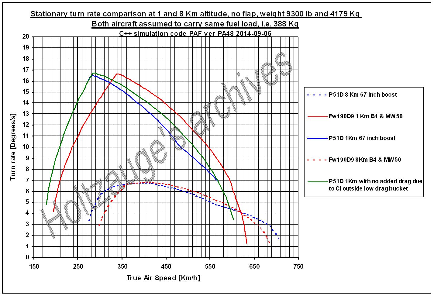
Based on some PM input on the turn rate figure I posted above I want to make some clarifications: With the engine powers assumed, 67" for the P51 and B4 & MW50 boost for the Dora they are closely matched in turn rate as the chart also shows. However, if we instead assume 72 or 75" boost the P51 will outturn the Dora decisively. In general terms, adding wing area or Clmax moves the left part of the "doghouse" chart to the left which raises the intersection to higher turn rates at lower speeds. Adding power raises the right hand part of the chart thus also moving the intersection point up increasing the turn rate which is then achieved at a higher speed. So there are basically two ways to increase your turn rate: Add wing area and/or Clmax lowering the stall limit or add more power to pull yourself around in the turn. This also explains why the Dora does so well at 8 Km altitude I think: The best turn rate is no longer attained at Clmax but at a lower Cl and higher speed meaning that the power available to pull yourself around in the turn becomes more important than Clmax. Another way to illustrate the point is to assume a Dora without the MW50 boost. So assuming the Jumo213A is instead producing roughly the same output as the P51, i.e. 1700 Hp at Steig & Kampffleistung, this would lower the right hand part of the Dora turn rate curve below that of the P51 and the Dora fastest turn time at 1 Km alt would increase to close to 25 s, i.e. a significantly lower turn rate than for the 67" P51. This would then together with the fact that the majority of late war German pilots were not well trained go some way to explain all the pilot accounts of P51's outturning the Dora. So sure they did: Since Dora's with "Experten" at the stick and MW50 boost enabled were probably quite scarce the majority of the Dora's encountered were probably not that hard for a well trained late war Allied pilot to outturn. This is not even assuming that some of those P51 pilots probably had the possibility to go to 72 or 75" boost in a turnfight..... Edit: Assuming Jumo213A at 1900 hp Notleistung without MW50 yields 23.5-24 s turn time at 1 Km alt so still longer than P51 at 67" boost.
-
Well, I have not had time to try myself but I was kind of surprised that the C++ simulation indicates basically no difference: I would have expected the Pony to be significantly better up high due to the lower wing loading..... And seeing the turn rate is only 7.8 deg/s it takes a loooong time to turn: around 46 s....
-
Since the Clmax at zero degree flap discussion now seems to have converged I did some C++ simulations to gauge the relative turn performance for the Dora versus the P51D assuming a low speed Clmax of 1.35 and 1.4 respectively. I'm still assuming a low speed Clmax of 1.35 for the Dora because I don't think anything has come up yet that points to any better value. Concerning the weights, I have assumed the same fuel load for both: 388 Kg since this was the maximum fuel load for the Dora in DCS. I think comparing same fuel percentage is wrong since the P51D has a greater internal fuel load capacity and should not be penalized for this. So the same fuel load seems more fair. In addition, I think it would make sense to compare with an even lower P51 fuel load since an even fairer comparison would be to specify the fuel needed say for 30 min endurance or something similar and then use that fuel load in the comparison. I have also include two curves for the P51: One is assuming the high speed low drag bucket Cdo figure also for the turn which is IMHO wrong since the P51 laminar profile only gives the low drag bucket gains at low Cl values. Since we are here concerned with Cl numbers close to Clmax then the profile drag for the laminar foil goes up basically to the same values as for the conventional NACA-23XXX series foil. So reading off 16.7 deg/s for the Dora in the diagram gives a turn time of 21.6 s and reading of 16.4 deg/s for the P51 gives 22 s which is then a little quicker than historical data but that is of course due to the lower weight assumed. The resulting simulated turn times agree quite well with historical data I think since the figure compares the turn rates for lower but IMHO fairer weights than the usually found historical data which is for full internal fuel weight which is unfair for the P51 since it carries so much more fuel load. If I instead assume full fuel weight loadouts at 10100 lb for the P51 and 4270 Kg for the Dora in the simulation the result is turn times at 1 Km altitude of 22.6 s for the P51 and 22.1 s for the Dora which agrees quite well with historical data I think. So that the P51 turns better than the Dora at low altitude in DCS is not really historically correct IMHO, however seeing that the Dora in DCS outperforms the P51 in all other departments right now this may not be a bad thing for balance. However, the best way forward is probably to correct the relative turn performance as per above and also add the 72" and/or 75" boost option for the P51 to get both historical accuracy and a balanced plane set, especially seeing that there is basically no difference in turn rate at high altitude which surprised me really. Before doing the simulation, I would have expected the P51 to be significantly better at 8 Km altitude which is however not borne out in the simulation. BTW: Entering a Clmax of 1.58 for the Dora and 1.7 for the Me109K4 in the C++ simulation gives turn times of 20.8 s for the Dora and 18.3 s for the Me109K4 at full internal fuel load at 1 Km altitude which hardly seems historical but maybe Hummingbird/Kurfurst has another opinion? :smilewink:

-
Yes, I agree with what you say: There is a Mach influence on Clmax and this will lower the Clmax you can use in the turn. I also compensate for this in my sim because otherwize the turn times will be too optimistic. As you say, the laminar airfoil did have good compressibility properties but that was also something the NACA 23 series had as well compared to other contemporary foils, albeit perhaps not as good as the laminar foils. The Spitfire did quite well also in compressibility but that was more due to the thinner wing than the wing profile. Speaking of Mach, I did a quick dive test with the Dora the other day and I’m impressed that you have modeled the subsonic drag rise so well. I did not clock the details but IIRC then the terminal Mach was in the order of 0.75 to 0.8 and that this is so well modeled in DCS is a big step forward in sim modeling in general and since this is lacking in some other contemporary sims a big plus for DCS. I do hope DCS does as good a job on the Me109K4 elevator stick forces because some earlier sims got this wrong and at high altitude the elevator control was basically lost at quite low dynamic pressures which IMO was not correct since the Mach was well below the critical for the elevator and it seemed that it was TAS not the dynamic pressure (IAS) that governed the elevator behaviour. What is your opinion Yo-Yo and what are the plans in DCS on this point?
-
It seems a bit difficult to determine an exact value for the P-51 because in addition to what you mention above, there is also figure 29 on page 26 in the same report and there is also mention of cover plates over the gun ports so to determine a figure from this is tricky. I’m leaning towards raising the Clmax to 1.4 in my C++ simulation though. My rationale for this is that the P-51 needs a good finish in order to attain top speeds and that since these are the ones we generally assume anyway, we might as well assume good conditions at stalling, ergo 1.4 seems like the value to use. I think this makes sense as well because a lot of the German data we see is also for sealed and polished conditions. Anyway, did not Erich Brunotte bribe his ground crew with Schnapps and cigarettes to polish his ride? Yes Hummingbird: You do seem to have a penchant for pushing outliers in the data: high German and low Allied :music_whistling:
-
I did a calculation of the delta in Clmax as affected by a change in aspect ration 5.22 (Me109E) to 6.14 (Me109K4) and this only gave a 0.02 increase when I used the NACA 230012 profile Clmax 1.6 as base. So there is not much of a difference in theoretical Clmax between the Emil and the Kurfurst as you would like to believe. Concerning the 1.65 to 1.7 figure you can’t reason as you do: Irrespective if we are talking about the Emil or Kurfurst, the inner part of the wing will stall at around 18 degrees. At this aoa the slats are fully out because they start to deploy at around Cl=0.8 and are fully out at 18 degrees aoa and Cl=1.4 to 1.45. Now if we continue to increase the aoa, the slatted part of the wing will happily go along and the lift will increase on this part of the wing. However, what happens on the rest of the wing is that the flow separates and lift is lost. So the overall effect is that the wings Clmax goes down between 20-30 degrees aoa, ergo you reach your wings peak lifting capacity of Clmax=1.4 to 1.45 at 20 degrees aoa and if you go to higher aoa to try to utilize what the slats can do on that part of the wing, you loose more than you gain on the other part of the wing. You really need to let this go now….. Also, I think that the reason the F4U turns better than the P-51 is simply because it has an 8% lower wing loading and 8% better P/W ratio so no mystery there. Finally, I raise my hat since it is a rare day on the internet when someone concedes to being wrong about anything!
-
Well I agree with your statement about the high altitude turn but remember that most data available for comparisons of WW2 aircraft is for turn times at 1Km altitude and here the Clmax is important since the best turn time is attained at the intersection of the stall limit and the power limit at such low low altitudes. There is however a slight reduction due to Mach effects: For example, If I in my C++ simulation assume the Clmax for Fw190 is 1.35 then I get Cl available at best turn speed 1.31 at 1 Km altitude which is a slight reduction but the turn is still determined by the Clmax albeit reduced for Mach effects. At a higher altitude, say 8 Km the Cl used at best turn is 1.11 while the Clmax as limited by Mach is around 1.25. So yes, I agree that for high up Clmax is not limiting but at the low level most simulator engagements occur Clmax is important.
-
Yes, since the aircraft is stable there is a need for a negative force on the stabilizer/elevator to balance the airplane which will detract from the wings lifting force. So this could perhaps also explain the difference between the British Clmax value of 1.4 for the Me109E attained in flight, i.e. in balance and the German wind tunnel test. OTOH the difference could be due to how the wind tunnel correction factors were applied in the German test.
-
Yes, the 1.28 comes from NACA 829 which also states 1.4 (Page 9 figure 4) for the P-51 in good condition and no flap deflection. This is interesting since it can be debated which one should be used. One could argue also for the 1.4 figure because some of the data (especially cited high speed data) on German planes is usually given for sealed and polished conditions. In addition, since the laminar airfoil on the P-51 requires it to be in good condition to give the benefits of the low drag bucket (i.e. the usually cited top speed figures) it is reasonable also to use the 1.4 good condition figure for the Clmax as well.
-
No, I do not keep stating 1.4, I have said 1.4 to 1.45. The 1.4 comes from the British flight test which you studiously choose to ignore and the 1.45 from the German Charles Meudon wind tunnel test. You on the on the hand have persisted in stating 1.48 in bold text three times now for the Charles Meudon test. You cherrypicked the highest value in the test series results I have found which were 1.42, 1.45, 1.44, 1.42, 1.44, 1.48, 1.43 and 1.45. Taking the average of these we get instead 1.43 not 1.48 as the German estimate for the Me109E. So it seems my estimate of 1.45 was a bit too generous. Since I agree with Yo-Yo that Cl=0.6 at low aoa like the figures you posted seemed high, I had a closer look at the figures both for the F4U (Airplane 6) and the Shrike A25 dive bomber (Airplane 7) you posted and if you look at the fine print at the very bottom you will se that they are Clmax figures with full flap deflection: 50 degrees for airplane 6 and 60 degress for airplane 7. So your argumentation for a clean wing Clmax of 1.58 and 1.7 for the Fw190 and Me109 just went out the door I’m afraid. However, there is in fact a Clmax figure in NACA 829 for the F4U with no flap deflection on page 20 (Figure 14) and here the Clmax can be read off as between 1.1 to 1.25 depending on service condition. So based on your persistent argumentation on the likeness between the Fw190 and F4U we can now conclude that the Fw190 should have a Clmax of 1.1 to 1.25 depending on service condition. No wait, since you argued for the 1.28 service condition Clmax for the P51 we should select the service condition value which is 1.1 for the F4U as well and based on the likeness we should consequently assign the same for the Fw190 right? :music_whistling: Finally, how on earth can you call landing and take off speed figures evidence in this context? These are obviously with flap deflection, larger for landing and less for start, different between aircraft and different makers/user probably use different speed margins to stall. So there is no way you can use these to determine clean wing Clmax.
-
Yes, I agree about the principle: In most cases it is the dynamic pressure q that is the problem and this is seldom an issue up high. This is also most likely why some say the 109 came into it's own up high. However, if you go really high and dive steeply then you can get compressibility problems as well due to local supersonic flow over the elevator. But this is something all elevator controlled planes suffered from. However, in this respect the 109 and 190 had an advantage with the all movable stabilizer which can be used to recover if elevator runs into compressibility problems. Yep, and I thought it could be good to point this and the Mk108 accuracy issue out before the release because it is probably a lot easier to get attention on this now prior to release. If a model is released and things are not hunky-dory, it will be more of an uphill struggle to change things since we are all fallible humans after all ;)
-
Based on the way Hummingbird frames his arguments and his posting style I was actually beginning to wonder if Hummingbird and Kurfurst were one and and the same person but now that you are here I guess that is not the case right? :smilewink: Concering your statement that the Britsh Royal Aeronautical Establishment estimate of the Me109E Clmax is guesswork: First of all the RAE is a professional establishment so I don't agree with your opinion that they would publish guesswork. Secondly, I have actually read RM2361, Messerschmitt Me109 handling and manouverabity test, by M.B. Morgan & D.E Morris where this estimate is documented. Morgan was in his time a respected researcher at the RAE and what you call guesswork was actually a measurement with a swiveling pitot head suspended 60 ft behind the plane. Now the reason you trail a pitot is exactly for the reason to get an accurate measurement. So how you can call this guesswork is beyond me. Anyway, since you usually have strong opinions on Me109 performance numbers and have dissed our input and the RAE measurements of Clmax=1.4 as guesswork, what is your opinion on the Me109E Clmax then? Hummingbird think's it should be 1.7. So what is your estimate?
-
Well I agree about made up minds only in my opinion it is yours: You began by claiming that the Clmax should be 1.7 for the Me109 and have progressed from basing this on 2D wing profile data for slats and when this failed propping up your theory on data for an American dive bomber and a gull winged carrier based fighter based on the fact that they use airfoils from the same NACA family. Why this can hardly be called evidence has already been explained to you but you persist anyway. So to me it seems you are the one who has his mind made up not me. Remember that the onus is on you not me to provide credible evidence. I base my numbers on actual measured data on the Me109. Both German and British measurements place the Clmax at 1.4 to 1.45. You are pushing for 1.7 so it is up to you not me to provide the evidence for this. So far you are coming up short.
-
I really look forward to the Kurfurst as well and seeing how good a job DCS has done on the Pony and Dora I have a couple of wishes for the Kurfurst: 1) Do not like a certain predecessor sim make the elevator seize up unduly early: Problem with unnamed predecessor to DCS was that the elevator seized up at a certain speed irrespective of the altitude, i.e. it was modeled based on TAS not IAS. So up high, even if the dynamic pressure was low, the elevator seized up even though the Mach was way lower than the critical Mach for the elevator which of course was not very realistic. 2) In the same sim, the Mk108 was modeled with terrible accuracy and was spreading the shells all over the place even though the K4 manual listed a spread for a burst with the Mk108 which was way lower than what was seen in the sim. Granted, the Mk108 does have issues with low muzzle velocity and a relatively slow rate of fire which should of course be reflected in the sim. However, it did not chuck shells all over the place. So DCS, please do not like unnamed predecessor pork the Kurfurst Mk108 and elevator! :smilewink:
-
First of all, concerning the Fw190, I said start configuration not landing. The flap angles are listed 7-8 rows lower than where you read off the Camax value. Another plausible interpretation of the whole table section is that it all relates to the propeller Cl and Cd (Ca and Cw in German nomenclature). Anyway, the 1.58 just hangs in there and I cannot see how you can cherry pick it out of that table and claim it is the clean wing Clmax. Could be wing Clmax with flap angle, could be propeller Clmax. Take your pick. If this is your basis to claim 1.58 clean wing Clmax for the Fw190 you don’t convince me and I’m sure you won’t convince the developers either. Concerning the figure 30 from NACA report 829 you refer to as a setup you believe to be “meant as a copy of the 109” you are similarly mistaken: It is for airplane 7 which is depicted on page 2 and AFAIK is a Curtiss A-25 Shrike dive bomber. As Yo-Yo pointed out, you can immediately tell that this chart is not for a fighter configuration due to the high Cl at zero aoa. How you can refer to this as something you find representative for the Me109 is beyond me. In addition, the text specifically mentions that the Clmax was not improved by the slats and shows that the improved slat maintained the flow over the aileron part of the wing so that roll control is maintained just like i said in my earlier post. Anyway, this data is moot in the discussion since it presents data on the Curtiss A-25 Shrike bomber, not the Me109 fighter. Getting back to your theories on improvements due to slats and how these can improve Clmax, let me repeat the explanation I posted before in more explicit terms: A conventional clean wing will stall at around 20 degrees giving a Clmax of 1.2-1.5. Adding a slat means that the wing profile behind the slat has the potential go beyond 20 degrees aoa up to about 30 degrees and at this aoa attain maybe 1.7 to 1.8. So, if you add a slat that spans the whole wing you can theoretically reach 1.7-1.8 at 30 degrees aoa. However, a part span slat will only help the part of the wing behind the slat. The rest will stall and loose lift at around 20 degrees aoa meaning the max Cl you can take out of the wing occurs at about 20 degrees, i.e around 1.2-1.5. So apparently it bears repeating: the slats on the Me109 are there to retain roll control at stall, not to improve Clmax. In fact, the Me109 wing does not incorporate a twist (wash out) like many other designs to retain roll control making the slats all the more important in this respect. I hope this makes it more clear how slats work and why they were included on the Me109. So if you want to continue to push for a clean wing Clmax of 1.58 for the Fw190 and 1.7 for the Me109 in DCS it looks like you still have some ways to go.:smilewink:
-
First of all let me say that you can seldom from wing profile Clmax data (2D data) like you have posted make accurate predictions how much the Clmax for a whole wing will be because there are elements of span loading and boundary layer transport in the spanwize direction that make the 3D analysis and behaviour of the wing as whole difficult to predict. In addition, most wings have different profile thickness, twist and even profiles at the root and at the tip. Beginning with the data you have posted on the Fw190, the 1.58 Clmax figure you have quoted is from the section detailing the take off and landing aerodynamics: Note that the take off condition Clmax is as you quite correctly quouted 1.58 but that this is when the flaps are deployed 12 degrees. So if this was your proof of the clean wing Clmax=1.58 then I'm afraid you are mistaken. When it comes to the Me109 figure of 1.7 it is now clear where that comes from. You have mistakenly assumed that the wing profile Clmax can be applied to the whole wing: The problem here is that while the parts of the wing with the slats can retain attached flow to a much higher angle of attack (aoa) than the rest of the wing this can never be utilized because the rest of the wing will stall at a significantly lower aoa. The reason you put part span slats on a plane like on the 109 is to retain roll control at higher aoa so you avoid a departure in stalling conditions. The slats of the Me109 start to deploy at around 10 deg aoa and are fully deployed at around 20 degrees. However, the full Clmax=1.7 on the slatted part of the wing is not attained until around 30 degrees by which time the rest of the wing is hopelessly stalled. So, the object of the slats is simply to ensure that roll control is maintained. The maximum Clmax of the wing as a whole is reached at around 20 degrees when the unslatted part of the wing stalls. The Clmax of the Me109 has been measured both by British RAE and by the Germans themselves in the Charles Meudon wind tunnel. They both agree the Clmax for the wing as such (not wing section data like you posted!) is around 1.4. This is of course for the Me109E but if you for some reason think the Me109G and K will be significantly different in this respect and have a clean wing Clmax of 1.7 then please post some valid proof of this because you cannot expect to be taken seriously if you rest your case on the 2D wing profile data and an aoa of 30 degrees as you have done so far.
-
Can you source the 1.58 for the Fw190? That sounds high. The only 1.7 Clmax figure I have seen is in a Me109F aerodynamics summary doc that refers to landing configuration so with flaps deployed. Can you source the 1.7 figure please?
-

50 cal Ballistics/Aircraft Damage Model Questions/Concerns
Pilum replied to USARStarkey's topic in DCS: P-51D Mustang
When you say 20 to 40 min thats sounds higher than what I had in mind and will it really take that long in DCS? I'm not an engine expert but I would expect an engine to die in a minute or two if you lose oil pressure. Maybe a few minutes more if it was the coolant that got shot. A nice (and realistic) DM would IMHO be pilots bailing out of stricken aircraft a lot earlier than the sieves the AI coast around in today. Speaking of changing things, it would be nice if it became optional which DM model was used offline: either the one we have today or the plaver DM also for AI. -
I don't maintain TAS: Maybe it was confusing to post the first column after altitude which is TAS. The way I have it set up is I define a sea level speed for the climb and then this speed will be maintained as IAS (third column) with a reduction of the IAS used in the climb to get the best climb rate at any given altitude. This is what I get in the simulation and also what seems to be the case IRL because all pilot's notes I've seen all indicate a lowered IAS to be maintained for best climb as altitude goes up.
-
Low speed propeller efficiency too optimistic in DCS?
Pilum replied to Pilum's topic in DCS: P-51D Mustang
The spreadsheet data I posted data from above uses both calculated and manually input data hence the different number of digits so don't worry about that. I don't use the advance ratio or Cp in the calculation either. I enter the prop efficiency manually in the spreadsheet. My C++ simulation however uses a NACA dimensionless parameter Cs called the prop speed coefficient so it takes different speeds, power loadings, atmospheric conditions into account. I appreciate that R/C props is most likely also an art but you have to realize that the aerodynamics for a WW2 prop is quite different due to Reynolds number effects so as I said before, read the NACA report I linked and I think you will get answers to your questions like why you can use 5 blade prop data to estimate 4. NACA engineers think you can and I think we can trust them too ;) -
Low speed propeller efficiency too optimistic in DCS?
Pilum replied to Pilum's topic in DCS: P-51D Mustang
First of all, while the Cdo has a big impact on top speed it does not impact climb rate that much. Secondly, where did you get the 0.0163 figure from? Sounds on the low side compared to other estimates IIRC. Anyway, In addition to propeller drag I take exhaust thrust into account which has a substantial impact on top speed. Maybe the estimate you mentions comes from only accounting for propeller thrust? -
In NACA report 829 which investigates Cl max for different a/c configurations, “airplane 1” is the P51 and it actually has a Clmax of 1.4 according to this report. Note that this is the Clmax for the wing and that while Clmax figures for the wing profile as such may be interesting for comparing different profiles, they cannot be assumed to be automatically representative of the whole wing. In this context the 1.4 figure for the P51 is surprisingly high, since the Me109 according to full scale tests has 1.4-1.45 while the Spitfire has around 1.36. It should be noted that this is all low Mach Clmax and that Clmax is Mach/speed dependant. While the effect is naturally greater at higher alt (due to higher turn speeds) and at accelerated turns, it is also present at best sustained turn rates at low altitude. I checked my C++ assumptions and I have the Clmax for the Dora at 1.35 at M=0.2, 1.31 at M=0.3 and 0.8 at M=0.6. Can’t remember where I got the 1.35 from, but it shown the trend anyway. If anyone has some better data and references on the P51 and Dora, that would be interesting. A Clmax of 1.4 for the P51 seems a bit on the high side. Yo-Yo: Could you give us some input on what Clmax you have assumed for the P51 and Dora and how Mach influences this in your model?