Brewnix
-
Posts
519 -
Joined
-
Last visited
Content Type
Profiles
Forums
Events
Posts posted by Brewnix
-
-
I saw a nice old document here ref the "Gordon" fonts:
That's a nice find I found the font googling and I think the "Gordon Condensed" font looks really close to MS33558 font that I been using. The problem that have arised with the MS33558 font ill be switching to it if looks good in fusion 360.. old thread but good find!
-
Wow awesome job! I feel like its a game with 3d printing trying to find the balance with making parts that can be printed with out supports. Finding the right position less over hang. Curious what brand filament you are using?
-
Thanks I have looked at Sprint a couple times in the past. Forgot about it actually and its not a bad price. Well a really good price if its easy to use. I know like Fusion 360 longer I use it the more i'll learn its maker's way of thinking.Sprint Layout is the most easy PCB software I have tried, is just point, click and drag.Ways more easy than Eagle an similars.
Would reccomend using http://jlcpcb.com/ I ordered there two times PCBs for my MFD. Extremely cheap production and good quality. I also ordered PCB assembly for tons of resistors and SOIC-16 shift registers.Here is one of board what I got

And how it looked in Altium designer
Those look awesome! So am I correct you didn't have to buy 10 of those? Before they would build?
-
I recently had a PCB made for 12mm tactile switches for an F-16 ICP. I had tried all the free layout programs and found them cryptic an frustrating. I run CAD for a living, and I can usually manage most interfaces. A colleague at work suggest I try Express PCB. They have a free PCB layout program that I found was extremely intuitive to use. You can place your order directly through the PCB layout program. I think you have to order your first board through them, but you can request the Gerber files and take any subsequent copies to any shop. If you're in the states, which it appears you are, it's worth checking them out. Price wasn't rock bottom but quality and turnaround time were excellent.
Nice I'll check it out for I'm new to PCB making I have made a few PCB for my self and had them built thru OshPark! How does ExpressPCB prices compare to OshPark? I was looking at ExpressPCB's webpage and there prices are a little confusing. Only thing is Oshpark requires minimum of 3 boards to be made.
-
There was a thread about their F/A-18 throttle that was briefly available. It was fairly nice hardware, but had several issues, so they discontinued the F/A-18 throttle.
I am thinking there problems were electronic? With all the DIY joystick's and Arduino projects wonder what kind of market it would be if they built the hardware and mechanics and you figured out the electronics. Small arduino board with some shift registers and pots or hall sensors bam have a quality throttle with eletronics easily replaced if something got borked!
-
I use 0,4 because of threads and similar finer things. I used 0,6 for a while and it is super fast, especially on draft setting. This Prusament galaxy black has sparkling bits in it, it is just for effect but somehow printing lines seem to be less visible and I like it.
PLA is probably the strongest material, only drawback is stability on higher temperatures. But something like joystick never goes in hi-temperature regime. I like THIS you tube Chanel, there are many interesting material testing videos.
is testing of usual 3D printing materials and PLA seems to be winner.Yes your prints look awesome! Ok thanks for the links I have seen that channel before it is good info.
Not for sure if you browse Thingiverse but I ran across this and thought might be good to try or maybe take gears and re engineer in to what I want or just try to use it.
-
I actualy printed on 20% giroid infill, 4 perimeters, and 0,3 mm layer hight (draft option) on 0.4 mm nozzle. I used 100% before but it is really not necessary and takes so much more time. I only printed cams on 100%. Enclosure was on 10%. Dark grey material is Prusamet Galaxy black PLA.
Ok I was thinking of the speckled look that is was some form of carbon fiber filament. I know 100% infill is way overkill. And takes to long I have only done that on parts that I wanted to make extremely rigid. Have you tried other materials for printing? I went on a filament journey trying to find something more robust to print with. But nothing prints better or I feel more reliable then PLA. I guess unless your printer supports different material its a tweak fest trying to find the perfect setup. I have replaced my nozzle from a .4mm to a .8mm nozzle and it cuts print times in half. Since I do mostly structural based prints I didn't feel a need for .4mm nozzle. Had to tweak the heat and speed a little for more material leaving the nozzle.
-
-
Nice work! I believe in if you build it thick and print it at 100% infill it will be strong. What filament are you using on the dark grey pieces?
-
Eagle is free with Fusion 360 for personal use - which is free as per the following restrictions - https://www.autodesk.com.au/campaigns/fusion-360-for-hobbyists#get-started
Nice! I stand corrected. This is good find. I just downloaded the free version one. One thing about Autodesk webpage you have to dig. Thanks I wanted to learn Eagle but didn't want to learn while paying for it.
-
Currently free license doesn't let you use Eagle you have to subscribe to Fusion 360 monthly or yearly.
-
Found the problem. I have a my cloud hard drive which is connected to the router. This was causing the stuttering. Further info on this thread https://forums.eagle.ru/showthread.php?t=212325&page=4
Nice! Thanks for this link good info.
-
In this Diagram the button in question is S4.
When I press it, the other 4 in the row are triggered all at once. so is it ghosting in the other columns?
I don't understand why that would happen with this single button and not everywhere else though.
In your schematic for switch "S4" your using Pin D9? D9 on some of my many docs I have for MMjoy2 is "ADC13". Also S5 is wired D7 to D8 isn't that BC to BC. Just a thought.
-
Yes, I have felt it. I am thinking it's the lack of hand cockpit interactions. The constant fumbling around throws it off. I guess I have no muscle memory! So I am working building a physical cockpit.
-
UPS Clause just delivered a Buttkicker BK-SK simulation transducer kit to my home a few minutes ago. Transducer is smaller than I thought, but the amplifier is much larger.
I'll disassemble the pit seat and figure out how to mount it (probably going to need to drill out the rubber isolation mounts to 3/8s and separate the seat from the rest of the rig) tonight and tomorrow, and let everyone know how it works.
This should make those ramp strikes much more visceral!
I Have this kit too! And transducer does look small but don't let deceive you, it has a good punch. It was all I needed for my cheaply built wooden cockpit.
Just saw the discount did you get the discount "spring20"?
-
I have been fiddling with this font for while trying to get it to work good. I have later found out that in Fusion360 you have to explode the text and create a physical presence on the part for the tool pathing to work. The only thing that doesn't look good is the D. I have tried the numbers and they pop out fine with tool path. It also doesn't have any these character support " -=+ ". weird stuff shows up so I just use special characters from another generic font. All though the one program that produce this font with great results is CamBam. It makes the lettering perfect. But Fus360 is a better price for my hobby.
-
FYI! Ok so I ran into a problem when using the M33558 font. When using the letter D the inner lines are all messed up. Now it didn't matter much for the just looking at it but when I went to post process the tool path's in Fus360 it would throw a fault. So every time I use the letter D I have to redraw parts of it. So the panels when I am working on the tool paths I correct the inner curve and the top and bottom lines of the D. So far its only been the letter D.
Pre fix
After the fix. It's not perfect but it doesn't confuse Fus360.
-
Very nice, not been able to make progress myself due to life
Thanks! I definitely can appreciate the life problem.
-
So this is what have got so far. I have buzzed out 4 panels, 4 bases and 4 tops. I figure out formula for lettering. Using a .5mm carbide end mill pocketing the letters and 2mm end mill for holes and cutting out panels. I plan to paint the sides and top of the bases to cover the white that can be seen from the top. The current files I have uploaded I have to modified the lettering little when I build the tool paths in Fus360. Some of the lettering have to be enlarged to accommodate the .5mm and end mill I'm using. But it's coming along. I think I'm gonna spend some time to build a throttle too gonna draw up the panel and switches as place holder.. I do have to redo a couple of the base panels. I was not paying attention to the acrylic I was buying and the guy over the counter gave me 2 different sizes. So the bases are 1/4 and the top plates are 3/16. So I have acouple of bases that 3/16 I need to redo in to 1/4 acrylic. There not perfect but I can all ways redo and update later. The tops are held down and independent of the base plate so I can pull the 3mm screws and tops come off with out disturbing the panel. I also plan to use vinyl or aluminium tape to black out the areas on the bottom to eliminate the light bleed except for the lettering.
-
Nice
i build my cnc too for my simpit Harrier
Awesome! How is it working can you share a pic! How far along is your simpit?
-
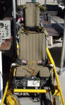
SO finally! I got my CNC router running and burned off some parts. Base panel looks awesome and the top panel looks ok but there was some flaws in Fusion 360 interpreting the tool paths which I have no Idea how to fix but I think the panel looks great for my first one. A couple of restarts broken bits and had to find some more acrylic sheets that would hold up to a router. Original one I bought kept melting. Local plastic guy says he thinks I got some stuff with styrene in it. I did have to adjust the lettering from 6mm to 7mm and make it bold just so I could get it to create paths for my 1 mm endmill I bought. Another road block I had was all the lettering I did on the files I saved I had to redo them when I extruded the panel to create the tool paths. I had to redo them on the face I was going to router it on. To extrude the panel and then the lettering form the sketch fusion 360 didn't like for some reason. I also still have too 3d print a box or since I have router now maybe I could cut out a box to mount my panel. I found this local plastic shop that has tons of products! Anyways super stoked with the router seems to be ok for home built.Once I get the side panels im going to finishing drawing the dash.
Franken CNC router.
-
I'm glad I found this thread. Your work looks awesome. I just started working on the canopy frame in Fusion 360. In lue of a quality photo or diagram of the frame, I took a screenshot in game. Using 5.75" width of the UFC for my base measurement, I calibrated the image to that. It'll be more guesswork than science, but it's a start.
Awesome. So all of mine are EYE ball guess work! But I based them on the size of the DZUS fastener layout. And try to make the lettering look proportional to the panel size.So hopefully they are close. Right now I have been working on converting the panels in F360 cam to gcode for routing them out. This has proved to be challenging! I am wondering how the lettering will turn out, When I measure the width of the lettering it measures .686 mm. Barley over half a mm. Then when I try processing the toolpath there is all ways a problem. Steep learning curve I guess. Thanks!
-
I am interested in the the Razbam discord. Is it invite only or open to anyone? I have not used Discord all that much.
What about Primer that is Black or grey then a top coat? I would also wonder out of too many coats if the paint is too thick would start to chip or flake. I painted a radio panel I built after I manipulated the switches into the panel with tools. The paint had chipped around the wholes and where I accidently dragged a wrench across the panel. Well I am no painter either so I could have messed up the panel paint job during the painting process.
-
Ok Thanks, I am finalizing my cnc machine soon and I am a little fuzzy on what to use.


Ideas and possibilities for my Sim Pit. thoughts please?
in Home Cockpits
Posted
Congrats! That is a very attractive price on motion. They have come farther in the motion products last time and it been a couple of years I looked at there products, it was 3dof. But the Stewart's platform is the best for motion. Personally I like the motion and one day will follow into a motion platform my self. There are some really big expensive rigs out there for motion but these guy nailed it for the the price and compact product. Can't wait to see your end product of your seat. Thanks for sharing.