
Brewnix
-
Posts
519 -
Joined
-
Last visited
Content Type
Profiles
Forums
Events
Posts posted by Brewnix
-
-
Hi, I was intrigue about this too. Just throwing this out there if you knew about the GitHub. There is a small section with DCS on it not sure what it has in it. Just in case I thought I would post the link.
https://github.com/SimFeedback/SimFeedback-AC-Servo/tree/master/Src
-
I must contend that I definitely still see a SDE in the Odyssey+, in spite of the advertised anti SDE technology. I've compared both simultaneously while being ran on two PCs and while there may be slightly more SDE on the Rift, it's still there on the Odyssey. The trick is not looking for it IMO.
Sent from my moto z3 using Tapatalk
Ok so on different occasions of using the O+ if i stop and force myself to focus on the screen its self i do see small little pixels. But to me its 90% percent better. I will not go back myself to the Rift. As for FPS currently my specs are I7 4790K 4.7 OC 16gbs ram and GTX 1070. I have not really set down to get a base line tweaking of settings. But i fly the harrier in a small mission with 8 stationary vehicles on the ground in Caucus and I get between 35 to 55fps depending location. Mostly 45fps.
I set the Steam VR Application to 200%
Video 100%
"renderTargetScale" 2.0
DCS PD 1.0
Texture and Terrain Textures High
Civ Traffic Off
Water High
Visib Range High
Heat Blur Off
Shadows Off
MSAA Off
Depth of Field Off
Lens Effect None
Motion Blur Off
SSAA Off
Clutter/Grass 0
Tree visibility 50%
Preload Radius max
-
So I have the Rift and the O+. Personally I have had no issues with running the O+. But I tend tinker any ways so to put my thinking cap on and learn how to tweak and make it better has not been hard. And the only tinkering I have done has been move a slider in steam VR setting and mod a few lines in steamapp code section. But the real reason I bought the O+ for the lack of SDE. I got this cause the SDE was my main problem with the Rift, the current resolution of the Rift would probably work for me if it wasn't for the screens! So to each his own I just wanted the throw this in here that the O+ is not that bad or hard to adjust.
-
You might of tried this but have you tried making custom rez thru nvidia control panel? My LCD tv are 1080 only but thru Nvidia CP I forced the rez to 7680x1440.
-
In the discussion on the steam forum https://steamcommunity.com/app/719950/discussions/0/1742229167208813376/?ctp=2, we analyzed data from several Odyssey Plus goggles - including for comparison with goggles on which DCS normally starts. We used the vrcmd application in the folder:
c:\Program Files (x86)\Steam\steamapps\common\SteamVR\bin\win64>vrcmd
This application generates such data:
Device 0 - holographic.WindowsHolographic - Samsung Windows Mixed Reality 800ZBA by WindowsMR - HMD - generic_hmd
D3DAdapterIndex: 0
RecommendedRenderTargetSize: width=1687, height=2107
Left Projection: left=-1.246544, right=1.040488, top=-1.439158, bottom=1.418004
Right Projection: left=-1.047278, right=1.232865, top=-1.418372, bottom=1.425465
Lens Center: (0.000000, 0.000000), (0.000000, 0.000000)
This is just the data from my goggles that have the effect of misalignment in DCS.
For comparison, data from goggles that do not have this problem:
Device 0 - holographic.WindowsHolographic - Samsung Windows Mixed Reality 800ZBA by WindowsMR - HMD - generic_hmd
D3DAdapterIndex: 0
RecommendedRenderTargetSize: width=1687, height=2105
Left Projection: left=-1.225003, right=1.041945, top=-1.414402, bottom=1.415475
Right Projection: left=-1.039288, right=1.240635, top=-1.423776, bottom=1.421235
Lens Center: (0.000000, 0.000000), (0.000000, 0.000000)
What you can notice is his top/bottom values are pretty close (symmetrical) to each other. Unlike other Odyssey+ headsets.
top=-1.414402, bottom=1.415475
top=-1.423776, bottom=1.421235
It is possible that this is a clue that will help in removing the problem.
Here are the next data from the two odyssey goggles plus with the same problem in DCS:
Device 0 - holographic.WindowsHolographic - Samsung Windows Mixed Reality 800ZBA by WindowsMR - HMD - generic_hmd
D3DAdapterIndex: 0
RecommendedRenderTargetSize: width=1913, height=2388
Left Projection: left=-1.237106, right=1.043276, top=-1.439004, bottom=1.414056
Right Projection: left=-1.045044, right=1.239822, top=-1.419550, bottom=1.431158
Lens Center: (0.000000, 0.000000), (0.000000, 0.000000)
Device 0 - holographic.WindowsHolographic - Samsung Windows Mixed Reality 800ZBA by WindowsMR - HMD - generic_hmd
D3DAdapterIndex: 0
RecommendedRenderTargetSize: width=2065, height=2581
Left Projection: left=-1.241200, right=1.041525, top=-1.444395, bottom=1.412439
Right Projection: left=-1.052791, right=1.237553, top=-1.431514, bottom=1.432223
Lens Center: (0.000000, 0.000000), (0.000000, 0.000000)
13WELT_JankeS, Ok so ran this "VRCMD" from the file ext you posted but where do i get the info it generates sorry I am not finding it. Currently I have no eye misalignment in the O+ it appears to be even. But I would like to help. Thanks!
-
"Looks great" is not really what comes to mind here, but the functionality is there. :D The rubber band is strong enough to provide the extra support I wanted, but it's by no means perfect.
Hopefully I'll find something a little more solid down the line, but the concept actually does seem to work with support going from side-to-side, rather than front-to-back (also seems to be easier to implement).
Well I was just applauding your ingenuity and quick thinking and thought it was spot on. I have been stewing more then a couple of weeks of trying to dream up 3d printed brackets with sheep skin covering for the straps, ultra plush. Some times I over look the path of least resistant.
-
For now, I did something stupidly simple - rummaged around the house for something, came across one of my wife's elastic strength bands, and use it as a makeshift strap going side-to-side. Did a quick session and seems to make a difference already.

Edit: Cut some holes into the band to slide it over the earphones; now it sits perfectly. Comfort level increased quite a bit with this (even though is ugly as can be). I am still looking for something more permanent down the line, but this is already much, much better for me.
Edit2: After some prolonged flying I can say that this really makes a difference. With that band distributing some of the weight at the top, the O+ facemask's bolster now sits more flush against my face than before, with pressure more evenly spread. Feels a little more like wearing the Rift now (scuba mask feeling comes to mind). I didn't have to tighten the back dial at all.
That looks great RRohde! This weekend gonna rig something up for my O+.
-
I guess some third party mod or DIY mod parts will be soon out on the market.
Something similar to this mod for Vive audio strap.
You will need to be glued some velcro on a side to attach sides and made some 3D printed clip to attach stripe on top. Get some ideas from this video.
Also, there will be possible just to relife weight from the forehead by attaching simple velcro from the side of HMD to strap in the middle near to headphones. The strap will connect this two points and distribute weight more evenly around the head.
Such simple and cheap modification with just glued velcro on existing parts without opening HMD should not lose warranty.
Thanks wormeaten, That actually gives me a idea. For my Track IR I have used Dual Lock Velcro to secure the Proclip to my headset and can easily be taken off but its strong enough to keep it from wiggling when you turn your head. Regular velcro I felt it was never solid. And I have never had it come unglued from it surface. I can propbably make simple brackets easy to 3D print and just Dual Lock it on the headset. As of right now I have been debating taking off the stock ear muffs. I use a set of astro's. So wondering have you heard anyone doing that yet? Thoughts?
EDIT Maybe these might work too, on my dirtbike helmet I replace the trap on my goggles with these. Kind of expensive but I think I have a set lying around. But to behonest the Velcro on these even when they got muddy never let go. And the hard wear is there already. Just got to get a strap.
-
some say taking a strap like that and just going from side to side adds support on the top of your head and it makes a difference ..
Oh good idea! I was plundering trying to draw and 3d print brackets.
-
Hey philkamul, have you gotten your d box sim working?
-
Great idea with that beanie - going to try that asap, thanks. Also curious how you get one what that strap idea... I was looking at something like this and wondered if that can be customized for the O+.
Nice! ya that's sort of what I was thinking too. Of coarse something that won't ruin the warranty but maybe a way to snap a clip to the front piece and back piece like the Rift top strap stretchy with Velcro. I imagine just a little more support around the cranium would make it a little more comfortable.
-
I have been really enjoying my O+, superb image quality, awesome colors, AMOLED magic at its best.
However, this thing is extremely painful to wear over time compared to the Rift, and that's the biggest downside of the O+ for me.
I mean, I end up what feels like carpet burn or pressure point pain on my forehead, and it's a real show stopper when playing for a while. The Rift never ever caused any pain at all, even after hours of using it.
How do other O+ owners deal with that?
Hey rrohde I have the O+ and have the same issue with the carpet burn feeling. I believe it has to do with maybe only a few points of contact when I wear the O+. Not a perfectly round head. I have adopted wearing a beanie or a soft hunting cap that's insulated, I know it not ideal but it works. I been thinking also of building a strap to attach to the top like the rift that goes over my grape for extra support.
-
Yes after encoder was selected they don't light up in red boxes anymore. Thats what the button tester was for. Cause it senses the encoders. But if you were to place your multimeter and check the switch across all pins. Middle pin to outside pins you see a momentary shorts on both pins at once. This why in normal button state you see both buttons light at once its getting signal from both traces. When encoder is selected it reads the encoder as intended digitally I guess I am not the exact expert on it but the twist left and right have 2 different signatures. And the shift function sounds like asyou described a way to assign virtual buttons to one button. I have never used the shift function. But I am glad you got it working for MMjoy is cool piece of software.
-
Ok thanks.
Yea at first that scheme was confusing me but after you explained how they work I got to looking and saw it different from what you said.
I believe in "Better Safe Than Sorry" rule....:thumbup:
For the encoder and testing purposes, if Im just testing one encoder are the diodes still required for testing a single encoder?
In my tests I think I had the diodes going opposite direction from scheme.:doh:
Your ok testing one encoder with out diodes. Its when you add a second row or column to the matrix is when its safe to have diodes
-
Thank you Brewnix, that works!
NP Blue73. Sorry late reply!
EDIT-Actually Blue73 how did you get it to pocket the text?
-
As I said above, wire switch separated from encoder in MMjoy2 inputs.
2 wires for switch in one row and column pins of matrix.
3 wires for encoder in another row and column pins of matrix.
Don't mix then. The PCB under this encoder is done for Serial connection.
I know nothing of the scripting stuff.What are those other encoders your using?
At this point I'll just buy some regular ones the everyone knows works for this purpose.
Do you know the difference bewteen these Im using and the EC11 encoders? I found a couple of others that built a similar box to what I want using the EC11 and Pro micro.
EDIT:
Yeah I cant get both the rotary and the SW to work together, its one or the other.
"Don't mix them" I apologize I didn't know that Thanks Sokol1.
Rabidscoobie so the encoders I bought I got off Ebay. seven apiece from over seas. I did not look at to what type of encoder they are I just grabbed them and after ae few weeks I got all 6 working in a matrix. So how different are my old ones to the KY 040 I don't know. I would believe that the encoder you pulled off the PCB is standard and wired the same as mine. My main goal was to get the KY 040 working with my known working matrix but as Sokol1 stated its for a different setup with the PCB.
-
Yes I did.
I was reading up on these encoders and they are called quadrature encoders,not what other kinds there are but hoping these are the right ones for what we are doing.
ok interesting, I didn't know! Well I did get it to work with the new ones but I couldn't get the twist and the push button to work together. It was either or. I switched back to use my old stand alone encoders not the new ones like yours. Mqybe that's why it started working. I did almost post a Arduino library link for ya just because I saw it on the Arduino site. It was for the KY 040 encoder and had script for it ready to go. Maybe that might be the way to go. Just a thought.
-
Ok that last post made more sense to me.
Making sure I have this right.
So when adding encoders I need to connect them first in the matrix then add all the other buttons and switches afterwards?
I have never messed with these things and they are a pain.
Im gonna try your settings in the pic and see what happens.
EDIT:
I just did it exactly like you said in last post and I get nothing on the encoder buttons,nothing lights up. Windows Joysticks shows 6 inputs but nothing lights when I turn it.
Wired the 2 outer pins to BC D0 and D4 and the middle to B3.
EDIT:
I think I may have the encoder part working. In MMJOY I dont see anything light up. In windows joystick it will light up buttons 1 and 2 just like button presses but only on every 2nd click of the encoder.
Is that the way they function on the clicks?
I also tested it in game just to see and it did do what I put the key bind to but just doesnt show any lights in MMJOY or in the tester,
Yes!!! I adjusted the clicks with the Timer. Timer 1 mine set to 60ms on+off it sets how long the press is held. So when you open VKB button tester did you select the equipment in the pull down menu above the buttons lights? Because encoders don't show up when you use them in the regular button panel of mmjoy.
-
Ok that last post made more sense to me.
Making sure I have this right.
So when adding encoders I need to connect them first in the matrix then add all the other buttons and switches afterwards?
I have never messed with these things and they are a pain.
Im gonna try your settings in the pic and see what happens.
EDIT:
I just did it exactly like you said in last post and I get nothing on the encoder buttons,nothing lights up. Windows Joysticks shows 6 inputs but nothing lights when I turn it.
Wired the 2 outer pins to BC D0 and D4 and the middle to B3.
So I just wired the encoders first. Also try to "clear button set" every time you make a change. I never cleared button set after change but today I did maybe it helped. Also I am not for sure if encoders are supposed to be first I just decided to do it that way for simplicity reason. I also understand you on the frustrating part because I am in same boat. Electronics is a hobby for me and I just started getting in to because of this sim. So you will get there. And there also might be unknown variables that we don't know about or aware of with mmjoy or promicro.
my current wiring pin setup.
Encoder 1
Middle pin B3
2 outer pins D0,D4
2 Push Button pins B3 to E6
Encoder 2
Middle Pin B3
2 outer pins D0,D4
2 Push Button pins B3 to B4
-
I understand I have been working trying to get the PCB one to work I think the stand alone are the ones to use. So to your question about the how they light up they should light individually. I currently have been trying to attach my stand alone encoders and having same issue. Oh for got to tell you only program the encoders in the first 12 buttons. You can change there button number but encoders only work in the first 12.
What I have programed
B3, B2 for BR
D0, D4, C6, D7, E6, B4 for BC
I could not get it to work. Until I took this apart had it working.But currently I just got this to work The problem I think was I Used B3 and B2 but was not using the pin B2 at all nothing plugged into it. 1 hour of scratching my head I finally just knocked it down to just pin B3 and the same 6 BC above and bam the encoder and push buttons work. Maybe try 2 encoders first this set up! I think having two or more BR when not in use was the problem. Maybe try this setup and see my mmjoy pic! also pay attention to the timer. I placed them at 60ms cause when I built this radio panel that was sufficient to turn the A10 radio freq numbers one digit. Oh and have you been using the VKB button tester! Its the button below it reads the encoders.
-
Ok I see np. Your Pin out looks great
EDIT-Ok so I wired one encoder up reflashed promicro. I get it to work SW fires but when I twist the encoder both direction it fires the switch too. Is this what you were talking about? I m think it you might be right to cut the trace or snip the one leg off the in side of the sw and hard wire off PCB. So my previous setup all the encoder sw were wired in to a shift register so I didn't have to try to incorporate them in the matrix. Gonna try one more thing roll back to previous stable version of MMjoy.
EDIT-EDIT-Ok another try with the previous version of MMjoy and in twisting the encoder it ghosts the sw button. I believe its the resistors is the problem it should be diodes it probably would not ghost then. Interesting.
-
Before you cut the the traces can you tell me what BR and BC assignment and how you defined the button you set in mmjoy? when I posted the pic of mmjoy I circle everything that sets the encoder up as reference. But because you have a sw involved you have a different setup per the last wiring diagram. Also later today I will set a couple of encoders up with this setup.
-
PCB in this KY-040 Encoder more hinder than help for use in MMjoy2, because are resistors in PCB and common pin for Encoder and Switch are shared.So if I just remove the PCB from the encoder then it would work and wire up like a normal encoder?
Then I just run wires for the press down switch into the matrix just like all the other buttons I will be adding?
But if I leave the PCB on then I lose out on the press down switch,correct?
After playing around with placement in my enclosure I was thinking about removing the PCB anyway. I dont mind removing them,I dont have a lot to do these days and I enjoy this stuff.
I got these cause they were kind of cheap and included the knob caps.
So far from the help I have gotten from this thread over the last year or 2 has been great.
Sokol1 is correct, I didn't realize when I bought these my self that they shared the one pin. All though I believe you should be able to add the SW in to the matrix. maybe wire like this. Sorry for all the crude drawings
-
So no you can start with one BR and daisy chain that with 3 encoders then all outputs would be individual to the BC. And common ground is ok. here a 3 encoder setup. But as soon as you add another BR to for another 3 encoders and 6 more outputs to the BC pins then you add diode to the outputs!


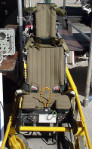
SIM chair help
in Home Cockpits
Posted · Edited by Brewnix
Can you place both on removable bases. Use a Bolt and wing nut to tighten to the chair. Mount the bolts to the chair. Kind of like this!