85th_Maverick
-
Posts
188 -
Joined
-
Last visited
Content Type
Profiles
Forums
Events
Everything posted by 85th_Maverick
-
You surely, not probably, need to train more!
-
Thanks "nightwawk"! So ED are finally finally thinking to improve the G effects according to before and after warmup periods as well as an averaged best possible number of seconds before a trained pilot blacks out at 9G, when starting from a relatively rapid onset. We've seen a lot of YT tests on which pilots can stand at even 12 vertical Gs for almost 15 seconds..., but for all these years our DCS pilot blacks out (even after warmup, it doesn't make much difference) in 5-6 seconds at just 9. But interestingly enough, most of the DCS pilots have learned to abuse the G effects model such that even with or without warmup, if they go and hold no more than 7.9Gs, they can keep that forever without actually blacking out even if initially the screen becomes black and eventually, some 10 or more seconds later while still holding 7.9Gs, the screen starts lighting up and you'll almost see normal, while still holding 7.9 for good. I just wanted to remind that aspect!
-
Irony or not, he's ironically right, and not because an MIG-29A dies easier from an F-18 in real life in close combat, but because the DCS F-18's engines are a bit overrated at both MIL and full AB power (same goes for the M-2000) which gives the F-18 an undeserved turn rate! Cheers!
-
Ok, I've been speaking about a list of the things that I wanted to talk about regarding what the missiles data file contains, which ultimately simulate most of our air to air missiles flight performances. There's so much to talk that I'll simply quit the idea of listing everything that would be useful to be discussed and stick to what's more important! I have spent about more than 2 months since that post in order to gather enough important data needed to conduct some personal analysis (using part CFD, part further math corrections) and also to see how our missiles are modeled in DCS. For the air to air missiles model used in DCS, I've found both good and not so good stuff, which the data file proves. First of, the flight model of the air to air missiles in DCS (which is basically made up of series of equations that require some input variables) is quite rudimentary so to speak! I only hope the planes are not simulated this way as well, although when it comes to transonic regimes, our planes in DCS also don't simulate any kind of lift reduction and drag increase, but I'll just completely ignore that..., although speaking of witch ("Nighthawk" also mentioned it as an example), the BMS Falcon does simulate a bit of aero coefs fluctuations as the planes accelerate/decelerate through transonic Mach regions. Not a great enough variation in there either from my opinion, but at least there is something, other than nothing! Now, about the DCS missiles model alone, the transonic region coefs are either non-existent for being taken into the sim's built in equations or simply the equations don't respond to what it's being inputted for those particular coefficients. That k1 Cx0 coef simply adds up to both the subsonic and supersonic drag coeffs. It just adds it up as a constant. If you put zero to both the k0 and k3 coefs, you'll have a flat line (zero derivative) kind of Cx0 versus Mach function. So basically, the k1 can be left at zero and you can control the missile's drag for the 2 remaining conditions (subsonic and supersonic) only from the k0 and k3 coefficients. The lift model is just basically made up of a lift slope (Cy0) and an AoA at which you want the missile to be limited to. No stall onset curves, no transonic regime coefficients..., only two slopes (one for subsonic, one for supersonic) and a max AoA. Falcon BMS for example, uses data tables (or matrices if you will) which very nicely model how the aero coefs behave upon many factors, not just one, but anyway, I don't wanna talk about other sims, only DCS! From what I've determined, as I was also forced to use CFD to some extent, I admit it, but I didn't take whatever rose from there without a bit of reasoning and thrown it into the data file. I've taken the CFD determined lift slope at the lower AoAs, maximum lift coefficient and critical AoA (I didn't use the CFD for determining the critical AoA, but equations), done the corrections, extrapolated the results for different conditions (Mach regimes), finally determined the minimum speed for 1G on the normal axis of each missile that I've analyzed and then determined the numbers required to be used (partly calculated + trial and error tweaking) in the data file in order to have these missiles start falling at the more realistically determined speed. Surprisingly enough for those who believe that the AIM-120 can reach some alien lift, cause this is what we've mostly talked about here, the AIM-120B should start falling at ISA sea level at some 420km/h, while the AIM-120C would normally start falling at some 460km/h. Wow...! Well, translated to the difference in maximum lift or lift coefficient for the same AoA, the inputted lift slope was indeed almost 3 times greater than it should normally be. 3 times...! So "stefasaky" (I personally don't know him, but I'm glad he's also within the aerodynamics domain) was right when he talked about the insane G-loads that he witnessed in DCS on the AIM-120! An AIM-9M for example, has it's minimum (so called stall) speed at some 370km/h according to a realistic lift slope generated on all it's fins + body while being limited to just 7 AoA (or 0.13 radians as it's used by default in the data file). So even at 7 AoA, the AIM-9M, would beat the AIM-120 in terms of minimum speed and/or turning radius, but, ONLY after their motors quit (zero fuel), otherwise, the AIM-120s prove better turning performances compared to the AIM-9M alone. So on with most of other missiles that I took the time and passion to work on, missiles which listen to that data file. Some missiles, such as the AIM-54, R-530, R-550 Magic II and other, don't listen to that file so I probably won't use my time trying to correct them. Using the drag coefficients that I was able to determine (part CFD (but very little), part equations) for the missiles that I've modified, their maximum range is much greater (at least double) as they decelerate a lot more realistic. Basically, the lift and drag as a function of AoA that I was able to determine were adjusted to the DCS missiles using the few available coefficients of the missiles model. The drag is substantially more realistic as the missile's AoA gets higher. With the original numbers, you couldn't even tell much difference in deceleration between a straight flying or hard turning missile. From all the available missiles for players, only the AIM-7, AIM-54 and AIM-120 use loft navigation logics, while all of the Russian missiles are too dump to use loft? To make it fair for all the players, I would either turn loft logics on for all the player (at least, if not for the AI as well) launched missiles or simply have that option turned off! The lofting navigation can double or even triple a missile's traveled range, so it's kind of greatly unfair for a R-27ER (which also goes quick for chaff) using player to see that he has to already evade an incoming head on AIM-120C before he even launches his R-27, giving the fact that both aircraft close in on each other at the same altitude and speed. Now, the IR missiles immunity to flares seems quite exaggerated. It's known that lately an F-18 has fired an AIM-9X at a Syrian Su-22, and with a few pops of flares, the AIM-9X went for them like honey. The pilot then used an AIM-120 to shoot it down. By a lot of trial and error tests for similar scenarios, I consider to have come up with more appropriate flare resistance coefficients for most IR missiles! I would also increase the amount of seconds before the missile's electronics die, effect which simply makes your missile start pitching up and falling, no matter the actual speed (it can be 9999), as if the aerodynamic lift disappears (strange behavior). I'd also increase the time before the missile self-destructs. Now I don't know the actual real numbers, but I find it odd that an AIM-120's internal battery dies in just 100 seconds after launch and it's still far from it's head on target before reaching it from a realistic distance! It doesn't make sense that so many missiles have so little self-destruct time (and not minimum altitude) or so little battery life time, so I've personally increased those numbers to about double. This is the file that I've modified with the purpose of discussing and concluding right from wrong, only with the purpose of increasing their performances realism and give everyone a better view of how actually a real missile performs: missiles_data.lua I'm pretty sure that I'll probably deal with a lot of rough/tough response, but I'm looking forward to see both some true aerodynamicists opinions about how they fly with this modification as well as how the players (which can have more or less knowledge) find it! All the best for DCS!
-
Idk, I simply do not agree that the AIM-120A/B (especially C) is able to have almost the turn radius of an AIM-9X. With an starting wing loading of about 1300kg/m^2 (about 3-4 times greater than that of agile fighters), the required total lift coefficient (missile's aerodynamic lift + engine thrust at 29AoA) must be incredibly high in order to get the low enough required turn radius and required time in order to turn within those small room interception parameters. That is simply impossible for the Aim-120, unless there's something wrong about how we interpret the launching conditions, which ultimately let you guys believe that an Aim-120A/B can get close to the turn radius of an AIM-9X! Just like "stefasaki" said, the missiles get their greatest turning capability through the thrust + AoA combination at lower dynamic pressures, not from the missile's aerodynamics alone. At lower altitudes or simply higher dynamic pressures gained, the airframe aerodynamic lift generates most of the resulted forces perpendicular to V! With the Cy (which is basically a lift slope value) within the data file that has been inputted in the latest updates (1.4 for AIM-120C and 1.5 for the AIM-120B), the AIM-120C alone is turning about as good as a clean F-15! Does that make sense to you? Doesn't that make you wonder if something might be wrong? I personally consider that we misinterpret the very little data from that footage and create monstrous errors by trying to model our DCS AIM-120 from just that! Sorry, but without some detailed analysis of the missiles aerodynamic lift and drag, that's pretty unprofessional to just model a missile that you don't even see by what you try to imagine that would've happened and simply force some results just to make it credible. The video is not a fake as some are trying to bully me with or to make it look as I've said something like that. I repeat again and again, that we're missing something from the whole truth and try to model a missile using absurd assumptions! It's a fact that a known half truth can lead to an opposite conclusion than the real one if we try to fill the other half only with our imagination! Copy! I didn't know about this as I'm not standing all day on the forum to know everything. The WIP of the HUD data symbology is not a of big concern as long as the error isn't unacceptably great. You might wanna recalculate the Mig's Mach at 30000ft for that closure rate, knowing that the F-16 was at around 25500ft (climbing) at around 380 KCAS. I was wrong also to initially consider it was at Mach 1.4, but it wasn't as low as 0.85 either, because the F-16 wasn't supersonic at the time he launched the AIM-120, as just seconds after the "splash" call he was descending at around 280 KCAS. Well, if it makes sense to you then...! Yes! Before this change, the maximum AIM-120's lift was far more realistic! Copy that! So the "T" might probably appear once it goes off the rail or after calculating that it's within the safe minimum distance and not below. Indeed, equipped with the AIM-120's fins (at their actual size) and AIM-120's nose cone, the AIM-9M will surely generate greater overall lift force compared to it's original fins, but ONLY at an AoA as high as 29 or 30 which the AIM-120 can reach before stall, but otherwise if you limit the AIM-9's AoA to the originally low value, you'll get surprised to see that it has even worse lift now! So yes, the AIM-120's much higher AoA allows it to get a lower radius turn through the greater lift forces (AIM-120 airframe lift + thrust * sin(AoA)) even though it has more than 5 times greater wing loading compared to the AIM-9M. After the motor quits though, the AIM-9M still has a lower minimum speed (and as such, lower turning radius) than any AIM-120 simply due to the greatly lower wing loading! All of these matter! From what I've determined from my personal analysis though, if you'd put the AIM-120B fins (the best of AIM-120) and cone even on the AIM-9X, you won't see much difference in the resulted lift! This happens because even though the original 9X's fins are giving a slightly worse lift slope compared to the fins + cone of the 120B, the greater AoA it can get before the stall occurs, gives the 9X a maximum CL * the corresponding reference area with a result that leads to about the same lift! But still..., the AIM-120A/B/C are very heavy for the reference area they have (wetted or conventionally projected), thus the AIM-120 will still turn much worse even than the AIM-9X. In fact, the AIM-120 is probably the worst when it comes to turning capability (with engine running or not) among most modern BVR missiles. It's not meant for dogfight turning capabilities, but for higher speed and ranges. What footage you've got of the actual missile's maneuvers? Again, you're only counting on imagination for what actually happened! If you want good footage with how missiles can actually turn, here's one good evidence:
-
Copy that Nighthawk! I love having a decent conversation, even if contradictions can naturally occur in order to be debated! So, as you say it, the amraam also has a similar feature (yet we probably can't know the minimum safety distance), then probably the pilot might've launched the missile from further than 2.5nm at that 1200KTS closure head on. Idk, there's that possibility and then, the radar antenna indication wouldn't be erroneous in that footage, but there's something else we miss. The amramm, as you've said, even with the tremendous lift that has been inputted to it now, still passes behind the target unable to intercept it, so, should we increase the lift to even more absurd? It's obvious that something else is actually missing and we tend to accept something absurd here! How can we be sure that the video-voice timing isn't matching? If we could ever have the opportunity to talk with that pilot in particular and ask those important details from him, we'd be very happy to say the least, until then, we can more or less accept something more obvious from something too far stretched to be right! I had since 2006 and still do so up to this day, and not for the graphics, you can be sure! I understand that they've also relied on CFD, but, somehow their missiles have more natural drag with AoAs, more realistic max ranges and speeds vs altitudes, and not to mention the lift, which seems pretty spot on for what Mav-JP has done! Yeah, hehe, well, that's why I wonder if not the launch distance or launch angle is wrong from as from what we consider. Again, an amraam couldn't do that sharp turn like an AIM-9X. Facts about their goal and design tell that radar guided missiles aren't meant for being maneuverable (they are much less maneuverable than short range missiles). Then we have way too less debatable data from that footage (just unreliable) for our discussion in this case! Yes, I deduced that those are not the actual conventional reference areas of the real missiles to be used for aerodynamic calculations, but as they affect the actual lift/drag of the missile, then the Cy0 values must be set accordingly in order to obtain the right result (lift and/or drag) that you would obtain using the conventional reference areas for lift and drag for an according lift and/or drag coefficient. There's a lot that I'd like to discuss with you regarding my personal work as I looked into this! I'm only positively looking for the better of this sim, not the worse! Hear later. Regards!
-
Well, guess what! They have inputted almost ZERO drag increase with AoA. That's their "very realistic missile" energy loss! About the high altitude low mach (for a missile) insane g-load, you can rapidly calculate the lift coefficient for a conventional reference are of 0.127m^2 (not 0.05 as I quickly stated at the beginning) if the missile's weight gets to 109.5kgs (all fuel burned). You'll be surprised that they've made it at least triple =)) of what this should regularly be. Seriously, have a check for it! Welcome to DCS forums, where you'll get ridiculed in the most unimaginable ways if you dare say that something's wrong...! They are the boss..., you do as they say! You'll get it over time!
-
When did I say that what happen didn't happen? Why are you trying here? I've only said that something doesn't add up if you'd take only the radar data reference from that footage and said that the HUD type data references seem to be the more and probably only reliable data! So, by your logic and what you say, the target wasn't just slightly above the F-16's longitudinal axis when he fired the missile, which happens if I replicate it using the circles displacements and target range before launch, but some very high above the HUD position (at some 12 degrees up giving the radar data) and when he shot the missile from 2.5nm, the missile not only had to compensate for the lagg after launch (this is not an AIM-9X, but a poor AIM-120 A actually), but also had to instantly turn close to an AIM-9X to intercept that Mach 1.4 target in thin air. That makes a lot of sense to you, does it? I don't need to reply to you again if that's the case, you'll probably understand it yourself sooner or later! Regards!
-
Sorry to contradict you, but the wind tunnel is more of a scientific and true results gathering tool, than a CFD model which is a very cheap way of getting a good gross idea of how the airflow wants to develop, but NOT the right tool to gather to trust into if you plan to gather the most correct results! That's a fact and not by someone's will (FAA or EASA) to drain money out of your pocket, you're forced by laws to use real wind tunnel test results for a particular aircraft that you intend to build or modify! Couldn't they let you use just CFD and that would be it? Well, it seems that they won't let you do it for proven reasons! And that's because even with the latest CFD models, the results are still not satisfactory! Yes, both the CFD and the wind tunnel have their own deficiencies, but after you do the right corrections (walls, dimensions ratios between those of the tunnel and those of the model, Reynolds, Mach, wake, etc. etc. corrections), the tunnel resulted values you'll always get you more precise results for any configuration and situation! Using pure CFD, the results are closing in (yet still not as precise) to the real ones only for a given set/range of conditions, while anything outside those conditions will have your CFD results (lift, drag, moments versus AoA and beta) go more and more erroneous, and not by just a little! No matter how well you set the original conditions (equations used and mesh design), in the end it won't make any difference whether you're an engineer who has experience with real test results as well as a good sense for the right results and who also masters CFD or simply someone who learned and mostly knows CFD without little aerodynamics knowledge! They will both get about the same best CFD results, so it's not the engineer's fault at using it right, nor the CFD bound user at using it right. It's just the CFD's limitations that won't let you get everything you want out of it and as such it should mostly be used for predictive flow patterns and how the aero forces tend to grow, but less (if not excluding) for actual maximum lift coefs, stall AoAs and complete drag functions. I must admit that there are 2 useful exception for which the CFD seems to own it's greatest trust as it usually goes hand in hand with real data. That usually happens at low AoAs, normally below 8..5! Anything above that would start getting you off-track in divergent manner! The lift slope (lift vs AoA), the viscous and resulted drag coefs function as well as the minimum drag coef can be acceptably fair and may be used as an initial or predictive data out of most CFD analysis. That's merely your best benefit of resulted forces out of a CFD. The moments otherwise, are not so lucky! Even at low or close to null lift AoAs, the moments are still something that you must consider getting from true tests, if..., you want something good! ED needed data to build a better missile and they went the CFD route probably because it's a million times easier to doing a flight test program with a physical AIM-120 model. Copy that! I agree that it's the most cost-effective method, but..., they should consider the above limitations if they also want it realistic and not worse than it was by default (2 years ago let's say)! On the other hand I disagree that it's very expensive to try making a 3D print of each missile model out of the cheapest material, yet strong enough to resist low speed bending moments, in order of at least 50 newton meters. For gathering an acceptably more precise CL max, stall drag, stall AoA and Cm vs AoA functions for the model, it would be grossly enough if they'd resume to a 50 or 100km/h undisturbed airflow. Even those results would be a lot more accurate than what we see now! These coefficients as well as the critical AoA won't vary wildly with airspeed (between a high aspect ratio glider and a slender missile) between a very low Mach number (say 0.01) and Mach 0.3 near SL, especially for the missiles that we mostly debate here regarding their maximum lift coef! Indeed, the CL max and critical AoA will be growing from say 5km/h up to around 370km/h IAS or Mach 0.3 at sea level (usually this gives you a peak of the best performances) with the lift slope remaining relatively the same (almost no increase), but that maximum CL and crit AoA growth is not so outstanding and you can extrapolate the very low speed functions to more precisely predict what would happen up to Mach 0.3 where the peak takes place. To give you a hint, usually the CL max and crit AoA at mach 0.3...0.4 are 12% higher, so grossly multiplying your very low Mach or airspeed maximum CL with 1.12 would give you a relatively fair distribution. This won't give you the best, but this is better than nothing for the start. Between 0.3 and up to critical Mach, the lift slope will start increasing exponentially (the power is realistically somewhat lower than 2), but due to the constantly and more rapidly degrading critical AoA, the maximum CL eventually decreases towards crit Mach. (the greatest loss taking place due to normal shocks stall). For predicting what happens there, I wouldn't recommend CFD, but validated equations that can better estimate your numbers there. Idk about the latest uber duper CFD programs that use other fundamental algorithms, such as Lattice-Boltzmann theories, no longer the old Navier-Stokes models, so maybe they can also give you some right lift/drag vs AoA functions for both transonic and supersonic, at least for the low AoA range, but I wouldn't be naive to go with just that. Consumer flight sim, I agree..., but, even for a consumer dump, "not know much" player, having a high wing loading missile still fly with 1G lift force at some 280km/h IAS, that will hurt the eye even for the most noob guy! Seriously, at some point, even common sense will start ringing on you! I agree, but that's not the kind of answer for someone trying to point out that something's not correct as long as he knows it can still be corrected, which in the end is beneficial for everyone! If I'd ever do that (to try making my own flight sim) I wouldn't do it to persuade those who'd use it and tell them it's realistic! No! I'd do my best to validate what I'm doing for myself, make it as accurately as my money can help, but also open minded and patiently listen to what the others have to say! Who knows how someone can help me spot something, no matter how full of knowledge I can be, as there is always the possibility of having gaps in what I know, while a fresh set of eyes and mind, even with little knowledge can make me realize that there's something wrong after sharing me the tiniest detail that something could be wrong! That would put me on guard and have me trying to solve true from false solutions. I could actually be learning until I die and will never completely understand what I wanted (this happens as a fact for everyone), but I'll do my best to at least learn more and correct (there are many who understood/learned things wrong) and find ways to get the best out of my effort! If I'm an egocentric and stupid and force my own will onto what the other should believe, by telling him something like: "What I give you is right and don't question it", it's only a matter of time until the truth starts emerging and I won't save my unfair gained reputation for too long with that!
-
Totally agree, but then isn't the algorithm that calculates the displacement between the 2 circles the same for the DCS F-16 as in reality? I consider that the algorithm should be logical as it only tells me which direction should I fly in 3D in order to have my path intercept that of the target at any instant moment and if I continue on that course I will eventually collide with with the target. Isn't that the logic of the small circle? Cause afaik, that's not for the missile, but for my plane's target interception solution.
-
 Hello again Jcomm and I'm happy to hear you again! Could you please share that scientific paper with us too as a reminder? Sorry, but I don't understand the conditions that you've used in your example! So, if you have a crosswind, say from the right, you couldn't normally get a rightward yawing moment by the use of rudder and that you couldn't bank away from the wind? Normally, the AoA on the vertical stab+rudder should automatically yaw you somewhat rightwards (more or less depending on prop torque) as well as having a bit of uncommanded left roll (even for zero dihedral). Many thanks!
 -
Really? Copy that! So that stupid crap is still happening! There is no other simulator (especially not in reality) in which a prop plane starts wobbling in pitch/yaw if the controls are not changed, no matter the lift devices, speed, AoA. Any oscillation that can occur due to a sharp change of conditions should be naturally damped in less than 2-3 more oscillations, but not perpetuate or self-excite as I understand that it still happens! I was only curious (after quite a while of testing props in this DCS) if the abnormal gyro effects still occur when the propeller is standing still and from my tests that got fixed, but by what you say, those old dumb oscillations (since P-51 came in DCS) are still present when the prop is normally spinning but you have the flaps out and you fly at a bit higher AoA and high power! Sad!
-
Bravoooo! After almost a decade of discussions, the flight model developers for prop planes have finally understood (don't know after which update they have corrected this nonsense) that a stopped propeller cannot create any gyro effects when it's stopped! The P-factor will still definitely generate some random combination of side and vertical lift (depends in which position the prop stopped, the blade pitch angle and the actual plane's IAS), but even that should be merely indistinguishable by the pilot. Having gyro precession effects on a stopped prop though, and even greater than when it was actually spinning..., and even much greater when you would've also taken your flaps out! I decided to just keep my words for all of those anomalies, but you have finally fixed it and this matters a lot! Thank you very much for fixing that!
-
Don't want to sound rude, but they don't show any sign of even try to look at more important problems (leave alone the bugs) that are almost 2 decades old (since the DCS A-10C came out), but want to make a great reputation on YT and delight our eyes with new products. I'm also for bringing new stuff, but ONLY after taking care of stuff that shouldn't cost or bother much to fix. This carelessness is not going to be productive!
-
What are you saying there? So the real pilots get an "unrealistic" real plane behavior? That's what it sounds like what you've just said! Yes, every type of positively (usually positive, only gliders have it negative) deflected flaps will give different natural pitch down moment (what we normally call the pitching moment coef within the aerodynamic center). For example, the real plain flap types give the least pitch down for a given deflection, while multiple slotted fowler flaps give the greatest pitch down of all. The L-39 with a single slotted fowler, should be somewhere in between a plain flap's generated downward pitching moment and that of a tripple slotted fowler (from my knowledge, it should be closer to the tripple slotted fowler anyway). In DCS, the L-39 has a very abnormal pitching moment versus flaps behavior and it makes me wonder how ED (the makers) have managed to make the L-39s flaps give you hilarious/ridiculous pitch up moment during the extension period and then find just a very slight pitch down moment after it has fully extended, while the F-18 has a crazy abnormal pitch down with flaps out which even makes the F-18 jump in negative deep stall like thrown from a giant spring, spring which also holds it there tight (at around -50..-60 AoA) until you rise your flaps and start flying again! Makes no sense and there will never be none! In order to have a relatively good reference of how the pitching moment behaves with flaps (not necessarily need to calculate/know the pitch down moment itself, but only the tendency and up to some degree, determine if the resulted moment is abnormally high or low) you can simply trim your aircraft to a reference AoA (use only the pitch trim, leaving the stick released) and see how that AoA evolves with flaps. For the L-39, I've used 10 positive AoA and after I've extended the flaps, the AoA started climbing to 13.5, then went back to about 9. =))). Here's a track if someone wants proof: L-39 wrong Cm versus flaps deflection function indeed.trk That has nothing to do with reality and if you meant about that, you're perfectly right my friend! I didn't bother to see what happens at negative AoAs, although for a correct simulation, the differences should be about the same as what happens at positive. From my general experience (both a pilot (I fly gliders and GA) and aerospace engineer/aerodynamicist), after the flaps have reached their extended position for this kind of single slotted fowler, by not having any pitch control altered (trim or stick), the resulted AoA should decrease with at least 3 degrees, leaving you at around 2, if were flying at 5 AoA with them retracted. The function of pitching moment versus flaps deflection and AoA is non-linear, in such that as the AoA gets higher, the pitch down given by the flaps reduces more and more (due to the stalled/reversed flow on the lower pressure side of the flaps surface), but until the stall occurs, this type of fowler should give you anywhere between 2 to 4 degrees of lower AoA from an initial positive, or the same amount higher negative if starting from a negative one. Speaking of witch, the flaps, especially the fowler should also drastically decrease your critical AoA. The tripple slotted folwer of airliners decreases the stall AoA by as much as 5 degrees or more (depends on wing sweep and aspect ratio). Here, except for the Su-25 which is the only aircraft in DCS which does simulate different critical AoA versus leading edge and trailing edge devices, no other aircraft does it. This is a big, big failure on a simulator that brags to be realistic! Cheers!
-
Think of it! Almost a decade waited MI-24 + the Afghanistan map! Does it look like a great chance to reconstitute some of the missions they had there between 79' and 89'?
-
Exactly! That's why, no wonder how much it takes I want to wait to see the whole Afghanistan available in the detailed area. I'm sure everyone would enjoy having it complete rather than tared apart. Even if this would become the most expensive map to buy, I'm all forward for having it 100% covered within the detailed zone.
-
Earlier I've said (tried to quote myself for an answer and it seems that this forum just deleted that message intead): "And now, something went wrong...! As brilliant as it's FM was and how natural the plane was responding and flying when it came out, just try it now once again and pull the plane around in high alpha and beta to see what I mean! Instead of fixing those with big time problems, they've broken those which were good." Sorry! I rectify what I've said! I haven't tried it after a long while and now I've noticed something that I didn't like at all, something that I most likely haven't noticed (didn't test enough) the last time I've tried it some years ago!. It seems that they haven't changed anything at all in fact, but I've just noticed intriguing stuff very late. Above critical AoA (18 AoA for this aircraft) and up to almost 25 AoA and some more, any roll command that you give to the L-39 while trying to keep the Beta near zero (a full corresponding rudder direction should bring you closer to zero sideslip), will have your aircraft roll like there is no stall over the ailerons at all! Now I understand that it has been having this problem since it appeared and remained like this! How could this be? The people's answers here make me believe that very few to none actually understand what must happen (more or less, all the known planes are affected the same way)! In reality, for elevon and also non-elevon planes, the greatest rolling moment and rate (for no side slip condition) that you can achieve is near null lift AoA. It's generally around 0 AoA, but at somewhat negative AoA (usually no greater than -5) for cambered airfoils wings. For both elevon and conventional elevators planes, the greater the AoA (positive or negative) gets, the rolling moment and trimmed rate will start to slightly and constantly decay! As the AoA continues to grow, usually over between 50-70% of the critical, the rolling moment will start to become 0 more and more rapidly as you approach the stall AoA, even if you can still hold a zero Beta angle (sideslip) to denying the adverse yaw due to roll (at positive AoA). Still holding a zero Beta above the critical AoA, the realistic rolling moments and rates will become very low, normally less than 1-3% of the maximum attained at zero lift AoA. Above 30-50 AoA (the lower limit AoAs for non-elevon and the higher limit AoAs for elevon), on a real aircraft, no more rolling inputs and moments should ever occur. At that AoA they have already become zero. Indeed, for the DCS L-39, above some 30-40 AoA, the ailerons deflection don't give any rolling moments anymore, but between stall at around 17-18 AoA and up to almost 30 AoA (only above 25 it starts to diminish), the DCS L-39 rolls with no problem and this ruins a correct simulation quite a lot. You'll simply get something very wrong instead of the expected behavior if, for example, you apply cross controls at some 20AoA (2 degrees above wings stall). Instead of throwing itself into a spin towards the rudder input, it throws itself into a spin towards the aileron input! With the DCS L-39, if you go past the critical AoA and one wing drops (very realistic for this), you can just simply correct the wing drop by applying aileron in opposite direction to the drop tendency. Very wrong! In reality, that would rapidly send your already stalled wing into deeper stall and eventually into a spin. This doesn't happen in this game. Another problem is that the roll due to yaw isn't becoming opposite from a low enough negative AoA. For instance, the L-39 has nearly symmetrical airfoils, if not symmetrical. Any negative AoA value (let's say higher than -1) should have your aircraft start rolling to the opposite side of the rudder input with no aileron input (just pitch). On the DCS L-39, only after going beyond -15 AoA the roll eventually starts to develop in opposite direction to the rudder input. Again, you cannot perform a real maneuver that you would perform in the real L-39 with this issue. I don't even need to confirm that the real L-39 has to start rolling by itself opposite to the rudder input above some relatively low negative AoA. Even on highly cambered, zero dihedral and zero sweep (the dihedral and sweep angles matter a lot), when going beyond -5 AoA, the plane starts rolling opposite to the the rudder or otherwise said, in the same direction as the generated Beta. These things should get fixed before they become forgotten like other FM issues of other aircraft! Sadly, the A-10s also don't simulate stall on ailerons between stall AoA (16-17 for A-10) and up to 30 and even above, but..., at least the A-10s, although having quite some positive wing dihedral, it still starts simulating an opposite roll due to rudder above -12 AoA. It's still quite too high though because the DCS A-10C is simulated with symmetrical airfoils (utterly wrong), confirmed by having a zero G-load at zero AoA..., just that dumb! Only the Su-25 (among these ground attack planes) is actually correctly simulating the ailerons stall. Just above 17-18 AoA, the ailerons only produce greater drag with almost zero lift. Perfectly done. That's how a correctly simulated rolling response to ailerons and AoA should look like. But..., the Su-25 is also plagued from the too high negative AoA above which the roll will eventually start to develop opposite to rudder. Everything about these issues can be seen in the following track file. Yes, the subject is about the L-39, but I don't have much time to start making topics allover the place to point out the issues. The developers can see the problem from 3 references now: L-39 and A-10C (both aircraft), wrong rolling moments with AoA and aileron inputs.trk Please abstain your answers until later and don't waste my time unless you are an ED flight model developer or someone who correctly understands what I wrote! You have my respect! Thanks!
-
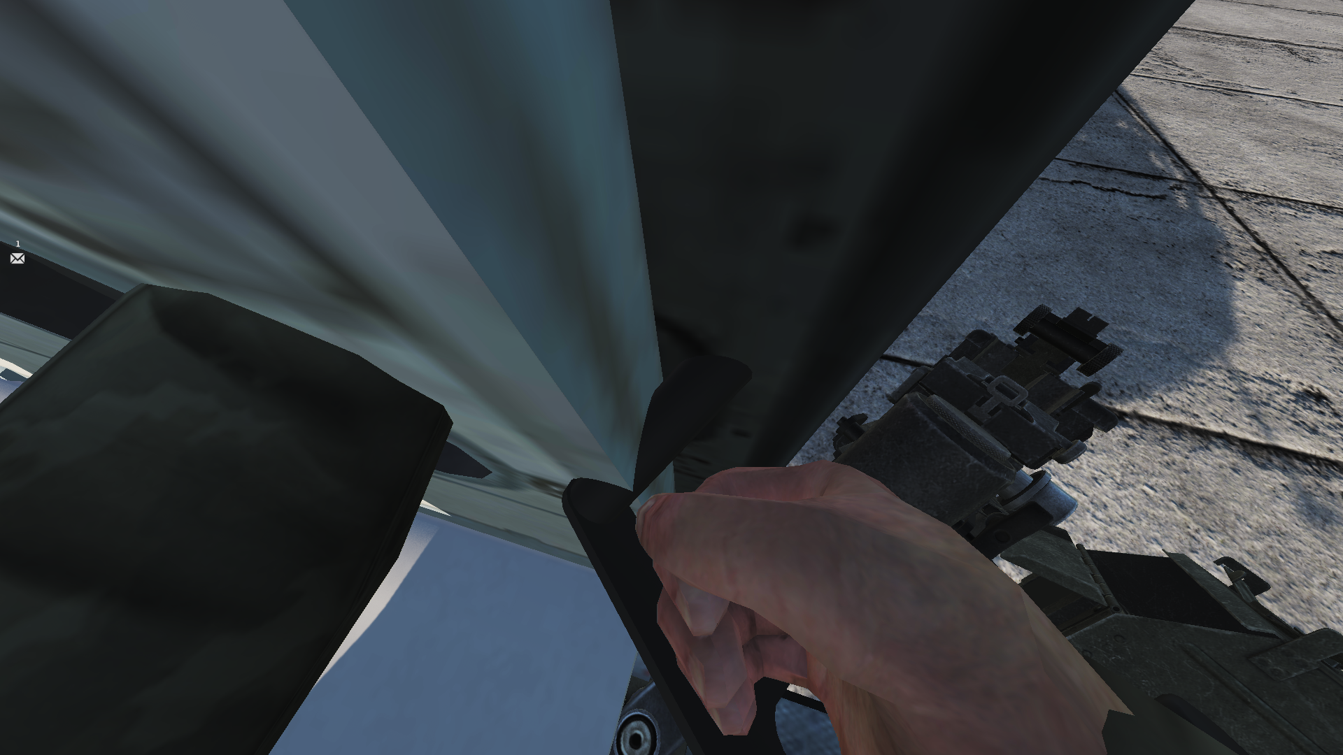
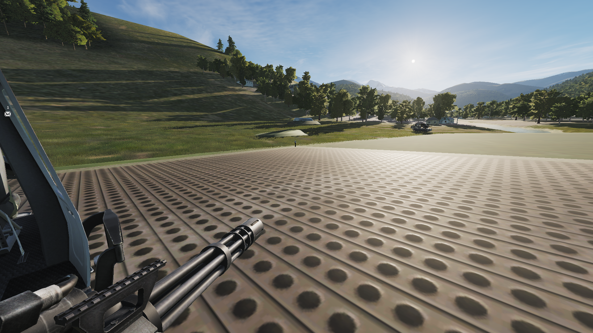
Hello, I don't know after which update has this come up, but at "some" update if you wanna play as a helo gunner in multiplayer, you'll have your view looking through the walls, chairs, whatever random objects, but never through the gun's sight anymore. Here's are 2 pics:

-
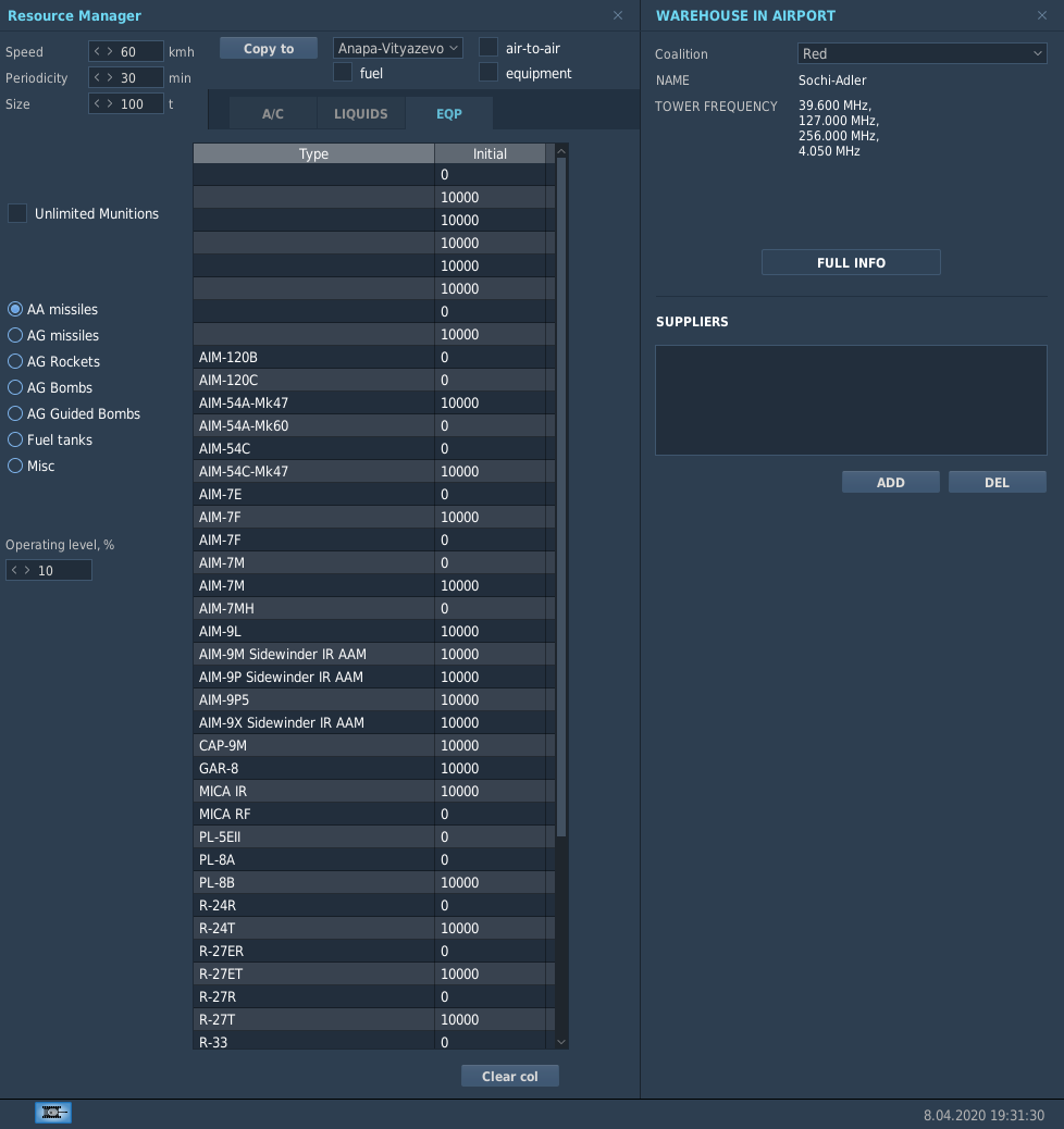
Hi! I have missions in which I have limited the number of various weapons at various airports and after every single update of the sim I must painfully rework all of the weapons tables once again as for whatever unique reason, the weapons names column shifts downwards a number of lines offset from their afferent number. Here's a picture of what it looks like after every update:
-
Hello "Stefasaki", I'm very pleased to hear of another real world (not CFD blind believer) aerodynamicist who can also look into it and discuss about it! Indeed, as you state, the lift = resultant forces perpendicular to the undisturbed airflow vector, therefore although we're used to call the lift as the result of airflow to airframe interactions alone (through the developed pressures field around the aircraft, excluding that affected by the propulsion system), most of the aircraft are obtaining their lift as the vectored sum of forces perpendicular to the "infinite upstream" airflow. But, even with the high lifting component generated by the AIM-120's thrust will NEVER be enough to make the missile out turn a 9G turning fighter at speeds below 1300 to 1200 km/h IAS, and I mean it! Just a simple but correct and verifiable algebra calculation can reveal that. Right now, if I come to landing with my A-10 at about 260km/h (140KIAS) I can see an AIM-120B flying right by me in the same direction but a bit slower without falling yet (I can reproduce it if someone really wants to see it for sure)! I do respect these guys trying to find the unknown using only CFD, but they're kind of trying to find something in the dark with flashlights on their foreheads but having them turned off (their common sense and logic is turned off). They will absolutely not be able to obtain the correct results using only CFD models! I'd like to cite a much elder colleague of mine who has experienced the results for thousands of wind tunnel tests through decades of carrer at the high speed wind tunnel: "Whenever I have finished a test run, gathered all the data and plotted the wind tunnel corrected (final) results for all the 6 aero coefficients, everytime I have a sense of doubt whether they are the real ones or not, but seeing these folks doing CFD tests only and believing even the first results they come up with, although they'll later use different initial equations and obtain way different results than the first and still want to believe they've done the right job..., it leaves me speechless of what they actually understand about the airflow in general!" I honestly can't add more to what that experienced man had to say. How the AIM-120B is now modeled in DCS, I can say that it has just slightly higher than appropriate critical AoA of 28 instead of around 24.5, but the maximum lift coefficient is incredibly high (roughly double) at around 1.5 as I can see it being given in the missiles data file. Just 15% more and the CL max of this AIM-120B's wings (fins) would have the F-16's CL max for which the wings have droops and LERX. This is total nonsense, but..., sooner or later the people will realize it! Normally the MIG-21's whole wing-body combination won't prove more than 0.9 as CL max which occurs around 21..22 AoA, yet these aerodynamically ugly fins that the AIM-120B has with somewhat reduced aspect ratio, flat plate type airfoils, higher sweep and mathematically zero taper should mostly produce 0.8, but in DCS..., 1.5, lol! Now that I have replied to you, colleage in the same science, I want to address the following to every CFD enthusiast here (I'm also one, but I'm more careful at choosing right from wrong) that uses only CFD and hoping to obtain simulation data to use for DCS: I honestly consider that the person in charge of doing aerodynamic analysis MUST always have a bit of experience with direct wind tunnel models, see for himself how the numbers usually get for various 2D wings (airfoils) or whole wings and aircraft mock-ups, see how the coefficients (lift, drag, moments) and critical angles tend to vary, including varying airspeed, for different but same airfoils from root to tip, different wing sweeps, different wing mounting types (high, mid or low wing), different taper ratios and the most important of all, different aspect ratios. Only after they have passed a bit through that and see a lot of real results for many types of real models they are much less likely to get fouled by unreliable CFD results. Next to the elder aerodynamicist bureau there was also a CFD department and even the leading person, a very experienced guy with lots of math and physics "onboard" (his knowledge) said that although they use a quite fine and well balanced mesh (to be effort effective) and sometimes even played with different types of mesh models in order to replicate similar tests that were conducted in the real tunnel, they were sometimes getting resultant forces 1.5 to 3 times different (as high as 200% error in other words) than the real resulted forces for various angles of attack tests. Most of the time, the lift errors were not due to an unrealistically determined lift slope (CL to AoA derivative) by the CFD, but by the quite erroneous CL0 (which we use to name the zero AoA lift coefficient) and the usually too high determined airflow separation/reversal aerodynamic angles (AoA and Beta). In some cases the CFD considered that the model won't find it's stall AoA until some 35-40 was reached, while the real model already stalls at 20..21. These are the stories of CFD limitations and they're not stopping here. Kind regards!
-
Hello "Dundun", I don't know what do you mean by ASE/ASEC (sorry I don't know all the acronyms), but as I've replied before, in order to get better results, we should try to simulate the same conditions as in that footage using only the circles displacement reference instead of the radar antenna reference while keeping all the other conditions similar and you'll get more reasonable to believe results than thinking that you can fire a missile from that altitude, closure rate, vertical displacement and offset angle (12 to 15 degrees given only by the radar antenna indication) and hit something. It won't work even with this exaggerated amraam lift that we in DCS today, which should be enough to tell that something's absurd!
-
Hello Ms. Tharos, yes I agree with you that my assumption of how quick he may have called the splash or not may be too erroneous, but honestly let's also use a bit of reasoning here. Ok, I take your word that it takes about 4 seconds to kill a head on target from 2nm at 1200 closure speed, but..., if the F-16 was at only around 300KIAS (about 445KTAS at 24500ft at ISA) and the closure rate was 1200KTAS, then the MIG-25 would've had roughly had 462KIAS (755KTAS) and in that condition do you want to tell me that at a density of roughly 0.45 times that at sea level and starting from just 300 KIAS (~550km/h IAS), the initially heavy AIM-120A (as I did a bit of searching I concluded that most BVR missiles weight about half after depleting their propellant) that needs to fly straight for less than a second (it's logically not programmed as a sidewinder to start turning just 2-3 meters after coming off the rail) then start turning with that great dynamic pressure handicap towards a target that would now already be more than 15 degrees up (if you use just and only the radar information form that footage) and within that a very low radius circle available it would have the needed lift (quite tremendous if you'd try to make some tests) to do about 100 degrees of turn in order to intercept the target? Sorry to say, but that's something only out of HAWX or probably ACE COMBAT, not out of a serious flight sim! So it can't be that the target was 12..15 degrees up when the F-16 fired the missile from 300KIAS, cause even with this already absurd AIM-120B/C aerodynamic (not including the thrust component) lift alone that is now used in DCS it can't hit the target from such given conditions even if you fire the missile from much higher initial airspeed that will help it correct the interception course before it's too late. I tried from more than 460KIAS to shoot using just that radar footage info (the track is in my above reply) and still misses by passing behind the target. The more reliable data that I consider worth for our discussion is the HUD like information show on the same monitor as the radar data. If you'd wanna replicate the same conditions by using only the relative position between the smaller interception circle next to the AIM-120's type circle, you will have a much lower and reasonable angular displacement through which the R-27ER will also have the needed room to maneuver and correct it's interception path. I've calculated that the maximum aerodynamic lift coefficient for both the AIM-120C and B which is used in DCS 1.4 (for C) and 1.5 (for B) respectively for a reference area that seems to be used in DCS (which includes more than the wetted fins projected area) of around 0.16m2 for the AIM-120C (0.4 squared is used in the AIM-120C's data) and 0.25m2 respectively for the AIM-120B (0.5 squared being used in the data file) are around 2 times greater the regular ones they both should have. For instance, in the "missiles_data.lua" file, the AIM-120C must have a maximum aerodynamic lift coefficient of 0.7..0.71, while the AIM-120B must have it at 0.73 in order to have the missiles start falling at the correct IAS. According to what I was able to obtain, the AIM-120C should start falling (normal G-load falling below 1 at critical AoA) at around 421km/h IAS while the AIM-120B should do that at around 380km/h IAS. The critical subsonic AoA (the sim uses just one number for any type of speed regime) of the AIM-12C should normally be around 26 AoA (0.46 in radians), while the critical subsonic AoA for the AIM-120B should normally be around 24 AoA (0.43 rads). Although it may not seem much of a difference, it's important that the critical AoA is also realistic, or the missile's performances will move away from being accurate as the thrust induced lift will be quite affected. People, don't self-blind your own knowledge and minds through CFD, it will foul you big time if you don't sort right out of wrong! I'll later discuss with you guys about what else I have found in that very important file, both the good and the not so good numbers!
-
Hello again Nighthawk and I'm happy to have your replly! Well..., indeed the radar antenna is indeed at +15 degrees in the picture you have provided, but the actual "beeeep" tone for the missile being launched takes place when the antenna is exactly at +12 degrees and the F-16 is slightly climbing from the earlier altitude of 23500ft+. During some new trials in which I tried to replicate the footage events I am usually some 1000ft higher (at around 24500-24700ft) when I'm about to launch it from 2.5nm away. For whatever reason, I thought that the missile fired in that footage is the AIM-120C, but no, in it's most probably the A model for that time! Even the B model was delivered later than 1992 when this footage took place. The A model will have somewhat greater maximum lift at critical AoA, even though the crit AoA may be 1-2 degrees lower due to the higher fins aspect ratio (it matters quite much). Now, lol, exactly as you state in your last sentence, that if you try to replicate those conditions, the AIM-120C won't even hit, but will pass behind the target completely missing it. The same happened to me, such as even if I tried shooting from 2.5nm away from about 24700ft (due to the slow climbing that I tried to mimic) when the radar antenna shows +11..12 (not +15 which is even worse), the aim-120C instantly turns up towards the target and misses it badly. But..., if you will try to replicate the scenario using just the HUD data (the circles displacements), you will not only hit with the AIM-120C, but easily with the rather more realistic turning R-27ER as well. So, what is your thought about this? My guess is that there either was something wrong with that particular F-16's radar antenna indication versus what the HUD data was showing (which seems to be the most reliable/correct) or our DCS F-16's radar antenna indication is wrong according to the target's displacement relative to the HUD data indication. I don't know! We have to agree that there's something weird here, but my guess is that there was no logical reason for that real pilot to believe that his missile will hit a target at 1200KIAS closure speed from a 10 degrees up from that high altitude and that very low air density from just 2.5nm away and think that the missile would hit. I strongly doubt that that's what the pilot had in mind and it's more than common sense that he had the target above him EXACTLY according to the HUD's indication, just touching the upper side of the HUD when he fired at it, not some 2 HUD heights above and hoping to have the missile turn for it as that wouldn't make any sense for a trained pilot as even his instinct would tell him that he'll miss! Here are 2 more tracks that I've done to confirm what I say: In this track you'll see how the AIM-120C misses badly from those impossible condition. Now I don't want to be misunderstood, but EVERYONE with a bit of common sense and even someone who has nothing to do with aviation or physics knowledge would doubt that a missile can be launched from this condition and hit that target: DCS AIM-120C's test according to the unreliable RADAR footage indications.trk There is one very important clue regarding the spatial displacement (horizontal and vertical distances through which the missile had to maneuver), which is the time it took since the missile was launched until it hit the target according to the pilot's "SPLASH" confirmation. From 2:32 the missile was launched, while at 2:41 the pilot confirms the hit. If we would estimate that the pilot was about 1 second or so late to confirm the hit, then the missile took 8 seconds from launch to hit. That tells a lot! It tells that the missile has more than plenty of room and time to intercept the target. In the following track in which I've used only the HUD indication and tried to match it as well as I could with that footage's real HUD indication, both the AIM-120C and the R-27ER took around 5 seconds from launch to hit and the results talk for themselves as the R-27ER turns then goes straight for at least one second before hitting the target flawlessly! DCS AIM-120C's test according to the more reliable HUD footage indication.trk Regards!
-
Hi, First of all, I'm sorry to have mentioned other things which are of another subject and hopefully I will now not grow it here and turn off-topic. Now, my friend, there is no logical reason why a designer would want his fighter to do phugoids even on a classical hydro-mechanical flight controls systems. Everyone hates to work trimming up and down every time the airspeed varies! If you build a FBW system, you'd normally want to keep your normal G-load constant at varying airspeed according to a given pitch input! At least that's how the FBW system's idea works before and after the Su-27 appeared! I doubt that Simonov wanted to have the Su-27 pilots work the trim up and down instead of focusing on fighting techniques! If you'll find a good enough example for what you consider to be the answer, I'd believe you, on the other hand your answer isn't valid due to the fact that the AoA actually varies wildly with airspeed for both the Su-27 and Su-33 in DCS! And here is the proof: Su-27 (and Su-33) upside down CM vs Mach functions.trk The Su-27 and Su-33 FMs are modeled such that the pitching moment (not only the coefficient, but also the moment) as a function of Mach for every AoA (at least below stall) have an abnormally positive derivative (slope) between 600 to 800km/h IAS. That is the only reason why only these two FC3 aircraft start pitching up like crazy (no known FBW allows that to happen) and that happens only due to the AoA increase while accelerating between 600 and 800km/h IAS. That is the only speed range for which the pitching moment coefficient slope is wrong. Below 600km/h IAS as well as above 800km/h IAS through transonic and continuing in supersonic, the AoA variation tendencies prove rather correct pitching moment slopes. Between 600 and 800km/h IAS there's a problem! On the other hand, the MIG-15 also suffers from the same abnormality! The MIG-15s AoA also constantly increases with airspeed. Even if it would have an all moving elevator it should also be affected by the so called "Mach tuck" effects, but the MIG-15 has a classical fixed horizontal stab and elevator config. Although it's a remarkably well simulated aircraft in all the other areas of it's flight model, sadly it is also plagued by the same issue as the Su-27/33. Regards!