ClayM
-
Posts
147 -
Joined
-
Last visited
Content Type
Profiles
Forums
Events
Everything posted by ClayM
-
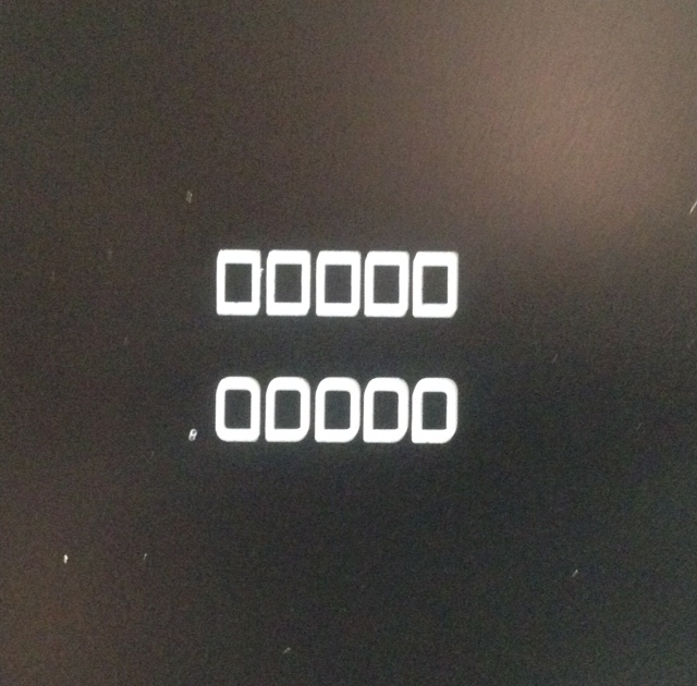
Lars I am aware of the font issue. I am trying to find something that will work as well. I think what you done looks great! I just seemed to me that single Q look really odd. Might just be me though! Keep up the great work! Clay
-
Here is my config/motor tuning MachConfig.bmp Thanks for looking Metal ( x and y are identical ) John, It was a couple of weeks ago when I fixed up a few backlash problems. I will check again. I will also have a look at CNCZone. Thanks Clay
-
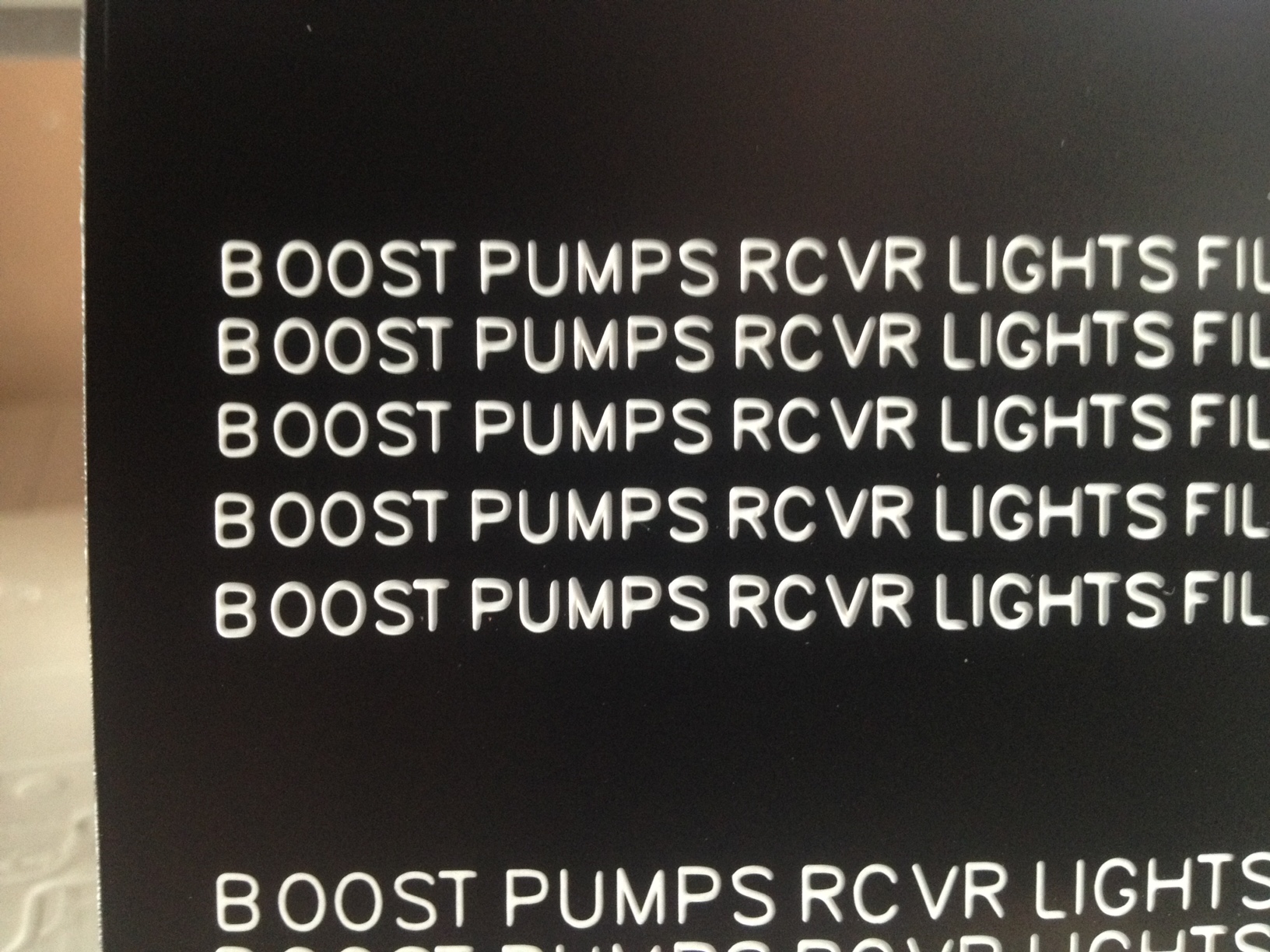
Here is the latest test This file was kindly provided by Warhog for testing. It may be hard to see in this poor quality pic but in my opinion the results are great! The x1000 ft per minute text turned out very good for being only .100" high. This was cut at 10"/min. At 30"/min everything goes for s**t. I have already fixed all the backlash issues. It was mostly from loose bearing fits and loose preload nuts. I know this is a pretty weak machine but I think this is operator error more than anything else.

-
You bet Lynx! Entire back covered with two sided tape. Probably time for another pass over it but with a .125" endmill it takes a long time! Clay
-
Metal Thanks! Sorry about the pic. All I have is my phone. Bottom line rectangles cut first 30"/min. I do not have CV selected in Mach3. Size is .110" by .075". Entry point of cutter is almost square but other corners are clearly rounded off. Top line all same settings except feedrate at 10"/min. Picture does not show well but there are now clean square corners. Looks much better! I had always assumed Mach3 changed feed rate during angular changes. When I set feed rate at 30"/min the feed rate display in Mach3 is always varying. I'll do more research on Mach3. Thank you for the advice! Also on my previous post you said it looks like the cut gets deeper toward the bottom on the second example. Your right it does. .002" , .003" , .004". Just testing out diffarent cut depths. Not looking forward to cutting at 10" a minute though. Thanks Clay
-
Some examples Top line .001" per pass to .003" depth next .002" .004" depth next .003" .003" depth next .001" .004" depth next .002" .005" depth .010" tip 60 degree cutter. RomanS font .110" high. Looks to be all kinds of problems here. The B looks almost like an eight! Same cutter but pocketing instead of engraving. diffirent font cut at 002", 003", 004" depth. Even at .002 depth the island in the A is almost gone. Any suggestions here would be greatly appreciated. Sharp cutter maybe has 3 hours on rowmark only. Lots of trial and error here! Clay
-
I'm sure this has brought up somewhere else in this forum but I came across some useful info (maybe). MS-18012B Google it. I think I found it on everyspec?? I would like to get some opinions on it please. Does this even apply to our application? I was going to use it as a guideline for my panels. Thanks Clay
-
Lars! Looks like you spent time changing this around since your last posts. I checked out a few of these new ones and they look really good! I can't give you any suggestions for changes because I do not know exact specs of original panels. I did however check out your CDU. Its one of the items I've always been missing in my pit. I was pretty excited to see yours. I think it looks great except for one thing. Is there anyway you can easily change the Q font on the keypad? I just don't think that one looks right( somebody tell me I'm wrong and I will shut up after I apologize ). It is still great work and thank you very much for sharing this with everybody. Look forward to seeing whatever else you come up with! Thanks Clay Sorry, Just found and ebay add for Rockwell Collins cdu and it has the same Q font as Lars'. So keep up the great work Lars! I will now listen instead of talking!
-
Thanks for the info! I have also found that I need to run spindle full speed all the time which seems to work OK. Metal Nice Font! Clay
-
From all the documention I have seen Gorton was the only engravable font that was approved for panel use. I'll supply document number when I get home from work. I have talked to a friend more computer savvy then myself and he said we could make that font if we have samples. The samples are provided in the document. I might give this a go for the hell of it. Personally I would like to have as correct a font as possible but Im certainly not going stop trying to make panels if that doesn't happen. Clay
-
Lynx Feed rate 250. I guess that's mm/min? So 10"/min?? I typically run at 30"/min. Also .003" deep with one pass with 60 degree .010" tip cutter. I'll give your routine a try and see what happens. What type of CNC machine are running? Thanks Clay
-
Thank you John! Still busy with work. Hopefully get something accomplished this weekend. I switched to the stick fonts as suggested and I'm having a little more difficulty getting good results. I will get dial indicator and confirm Z-axis is working properly. I'll post some pictures of whats happening. Anybody have any luck with Gorton font? Clay
-
agrasyuk Very nice work! That is the quality I am trying to achieve. One day hopefully I get there. Also I agree with your response to DM. Feel the same way.On one hand he says there is no demand for panels. On the other hand he claims to know every detail but wants to maintain control of this info. I think he believes there money to be made here. Yet if there is no demand how can it be profitable? Or he actually NEEDS someone to make panels for him and in exchange he will share his holy grail of panel info. The one fact here is that I still value DMs opinion and have a lot of respect for what he's done for others in the community. Clay
-
DM Is it safe to assume that when you say " people making their own versions of panels" means that their product is not accurate and not a reasonable representation of the original? How about you tell me who's making DM approved panels and I'll throw my wanna be cnc machine in garbage and buy those. It would save me trouble of trying to make them. Back to the task at hand. I seem to be having some difficulty getting nice text. Its either to thick or to thin. I'm going to do some tests with the same sample text and start at .002" depth and increase by .0005" and see what results I get. I will try same depths at different x y to see if it is a leveling or machine alignment issue.
-
DM LynxDk is in Denmark. Just trying to think about shipping costs. Why are you not producing anything yourself? Thanks Clay
-
LynxDK Feel free to discuss here! I would love to hear this! DM May i ask what continent your on? Clay
-
Rolling On Floor Laughing (ROFL) Deadman (DM) Please change your tagline to... Computer Numerical Controls (CNCs) and Laser Engravers (LEs) are great but they can't do squat without a precise set of plans...:thumbup: DM Are you saying the rest of us are making low quality products? If I just wanted to sit in a plywood box with some toggle switches that did *something* then i would not be going to all this expense and effort and bothering all the supportive people on this forum. I think it is safe to say we are all interested in making accurate panels. IHTG ( I have to go ). Wife calling. Clay
-
As warhog stated I'm using the wrong font. Currently trying to get RomanS font installed on my CamBam/Mach3 pc. Seems like AutoCAD no longer supports trial versions for Win Xp 32 bit. I use another pc for autocad so it does have the RomanS installed but that pc does not have a parallel port. So.... still messing around with the issue of stick fonts. Funny how the little details always cause the most problems. Also noticed some of the ballscrew support bearings where spinning in their bores. found there was x and y backlash that was not there before. I believe that the nuts used to preload the ballscrew support bearings are slowly backing off. So I took it all a part. Used locktite retaining compound on all bearing outer races. put it all back together and tightened up nylock nuts to set bearing preload. All is good. I suggest anyone who purchases one of these ( cheap 3040 type cnc ) machines to check bearing fits for the entire machine and bearing preload on ballscrews. Clay
-
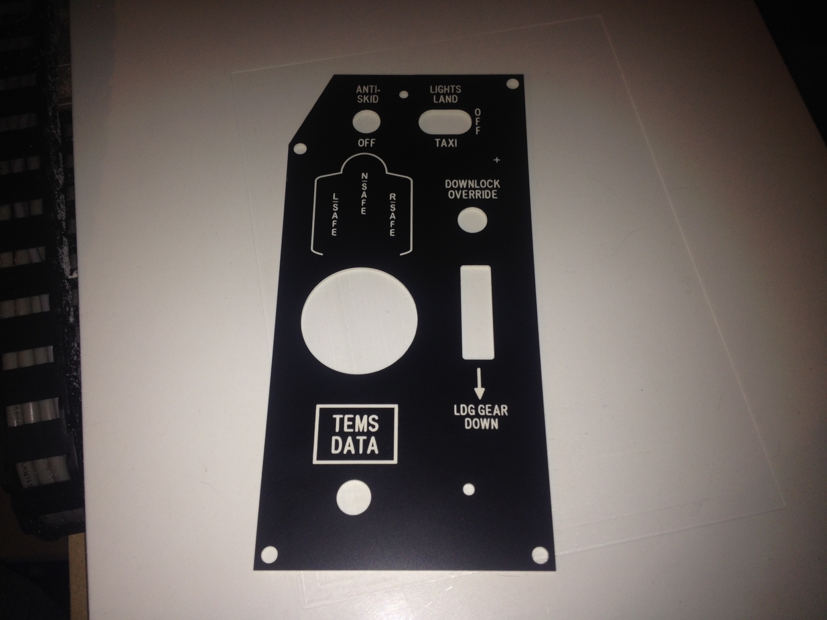
My thoughts for CLP is to cut multiple layers of something ( i have some 1/4" lexan)for the indicator boxes. Maybe 1/2" deep so 2 layers sandwich it together and paint entire thing with a few coats of black spray paint. next mask everything except individual indicator pockets. spray with gloss white paint. attach PCB with LEDs to the bottom and engraved light plate to the top. everything will be clamped together with the 4 holes that are in the lightplate. I suspect issues with light bleed from any gaps but i think i can seal it pretty good. Clay
-
It sure would be nice if I had more time try all the ideas being discussed here. At this point time seems to be the enemy. One thing holding me back a bit is " Cambam is thinking". I'm not sure if its a hardware issue on my end or software. I wanted to do a test/trial/see how it looks cut all the text on the CLP indicators.If I try doing POCKET on all the text in the same operation Cambam just thinks a lot and produces nothing. If i just try to cut 4 or 5 indicators it runs OK. From my experience so far i would think entire CLP will be around 25,000 lines of G-code!!! Does cambam have any limitations for any one operation? Anybody here have this problem? I'm going to try doing entire panel with 12 operations (so 1 row of indicators at a time). I will report back with the outcome. Thanks for all ideas and advice everyone!! Clay
-
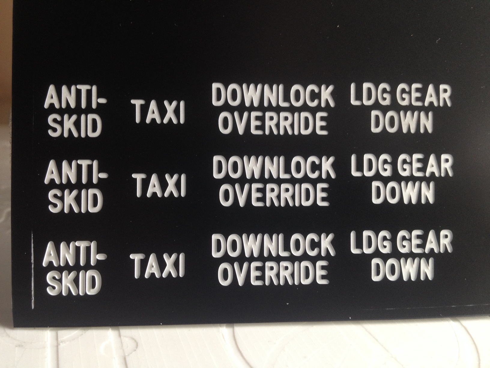
Thanks Everyone! Warhog Sorry, it might not be UHMW! getting my plastics mixed up here. I think its HDPE??? But the tape works great.Covering entire surface. Requires just enough effort to remove that you know it is holding tight but not a total pain in the ass to remove. I tried the regular spongy thick stuff before i found the tape you recommended and it was horrible. Dowel pins sound good. I had been trying to think of how to register the flipped piece. So are you saying use dzus holes in the panels or just use edges of the stock? Managed to get everything zero'd correctly (recalc tool path button does wonders) and even a tool change that worked great first try. Thanks. Now that I've wasted a bunch of plastic (and tape) to get the hang of this I think I'm going to attempt the caution light panel. After a couple years trying to get it to work it would be nice to give it the finishing touches it deserves. I will need to flip this as well so I sense some more trial and error. Clay
-
Making some good progress! Got rid of the mdf. Managed to scrounge up a 12" x 15" piece of UHMW. Spent most of sunday leveling it. Takes awhile with 1/16 cutter and .005" stepover. Warhog, Turns out my local staples stores carry that tape! Works great! Thanks for the tip. I screwed up one of my first cuts by selecting the tabs in cambam thinking i need them. now i know why you said cover the entire surface. eliminates the tabs! Brilliant. Here's what i have so far More to come soon. ClayM
-
I am going to get rid of MDF soon! I was just being lazy and using what I had kicking around. As my supplies keep building up I will make everything a little more "proper". I have received my order of cutters and the rowmark I ordered finally showed up. So things are progressing. I will see I they also have a crop that would work for the new base so I dont have to buy a full sheet. I have been doing a lot with Mach3 and CamBam and seem to be learning something. Still having a bit of trouble changing the origin in Mach3 so that I can actually set X zero and Y zero where my stock actually is. For example if I have a drawing in cambam that does not have the edges lined up along the X/Y origins then I have a hard time placing stock on the table in the correct position. Still working on it though and youtube videos have been great resource. Clay
-
Status update I have been experimenting with CamBam and have some mixed results. From previous posts ( i think a couple of pages back ) you can see I had pretty good results using HSM. Heres what i am getting with CamBam Setup as a .010" cutter. Using engraving routine. I'm a little confused why it would cut text to wide but still leave material in the middle. Never mind I just realized I should have used pocket instead. Is it safe to assume that engrave cuts on the center of the line instead of offsetting for tool radius like pocketing does? On another subject I managed to level a piece of mdf to use as a base to attach my work to. Using a 1/16" cutter to cut a 10" by 12" area was slow going. I would like to paint or stain or something the mdf to prevent the double sided tape from peeling the mdf. Any suggestions? I'm still a little hesistant to attach the work to the table. ClayM
-
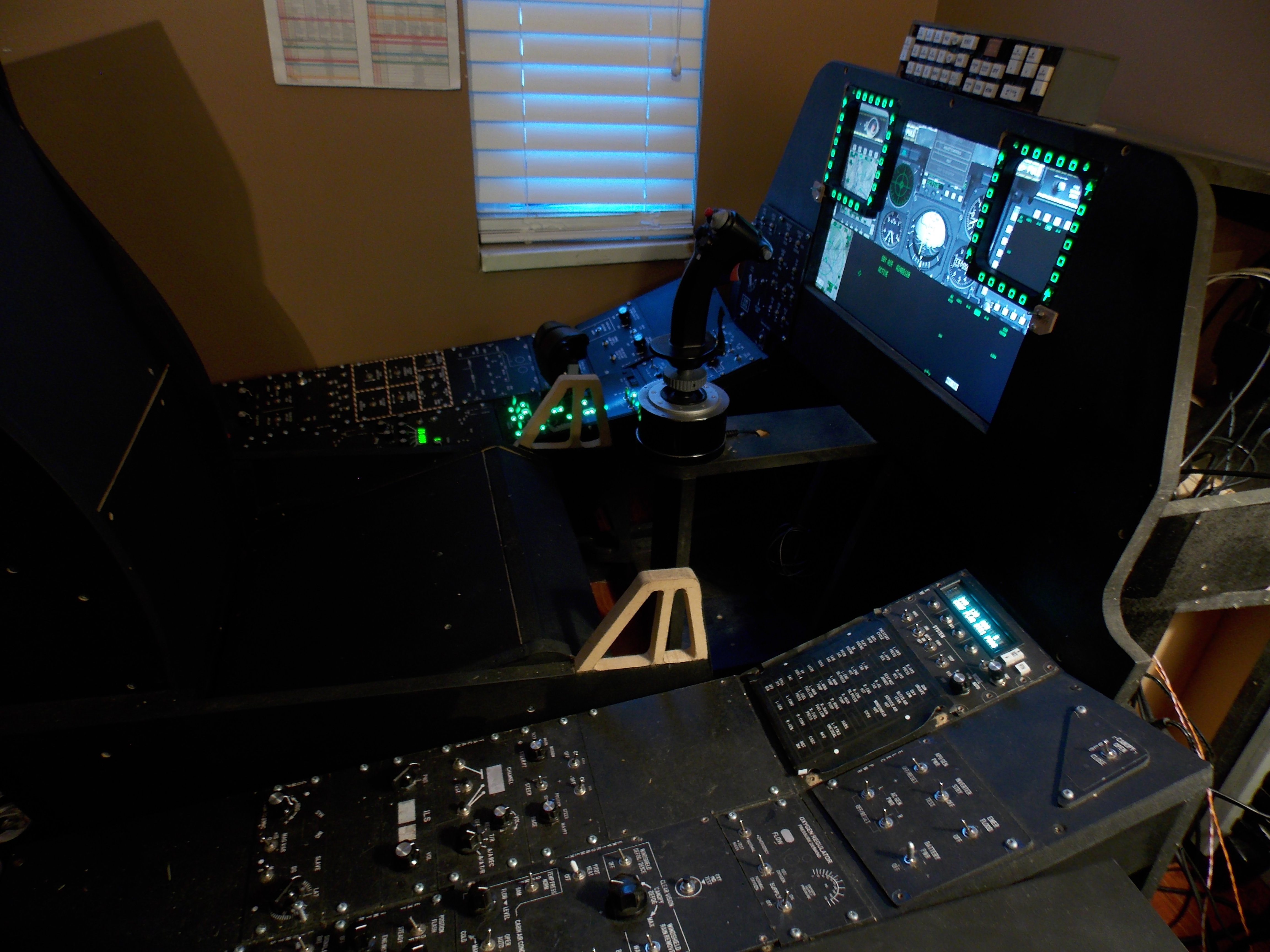
DM Thanks for tip. Hopefully one day I can have more accurate knobs. If I recall correctly you were producing these at one point. Is that still the case? Also is it just me or maybe I'm using the wrong knobs but are the shafts on common pots too long for our applications? Warhog I have to start taking notes to remember all this! I agree with never leaving cnc running unattended. I have had to use E-Stop a few times. What I have found with this machine is that i can set cutter depth in the collet at a point where at max -z it just clears the machine table. I accidently set wrong Z home once and the first thing that happened when i ran the program was plunging all the way through plastic and deep into my 3/4 mdf spacer. Luckily i had my finger on the e-stop and was able to stop it before it made any x/y movement. Engraving bits can drill through mdf like its butter! So the reason I started actually building the pit was that I had Dimebugs plans, Gadrocs Helios and what finally convinced me was reactorones panels! Following the .375" rule some of my current panels dont make sense. I've put some of Lars' panels through inventor and there is some discrepencies but they do look really good! I'd really like to just take reactorones panels as templates and go with it. Starting from scratch would take me years ( or never) and I would still be guessing at most dimensions. For example Lars' UHF looks fantastic! Comments please! I need somewhere to start. Otherwise I'm going to get my calipers out and copy reactorones panels. They have served me well for over 2 (maybe 3) years. I'm attaching pre-cnc pit pic now. Lets see were it ends up! (sorry missing main monitor. its hooked up to mach3 on another computer. guess i need another one) Thanks Guys Clay