ClayM
-
Posts
147 -
Joined
-
Last visited
Content Type
Profiles
Forums
Events
Everything posted by ClayM
-
Thanks DM! Good info once again. Clay
-
Still playing around with this.....:helpsmilie: I was wondering, with a real panel, is the actual switch hole supposed to be lit as well? I have been trying to keep backlight bleed away from the switch hole. I don't know why because I have never seen a real panel and have no idea if this is correct. Thanks for any help! Clay
-
Have you installed the LedControl library? Go to arduino website. It has info there. You then need to "install" the library in Arduino IDE. Clay
-
As I have said many times before....... Thanks Ian! Clay
-
Thanks for sharing Tore! Excellent work. Thanks also for the Arduino code. I already see some things that will help me out a lot. Clay
-
Looks like your making good progress! Please let us know how tinyG and chilipepper are working out for you. I have considered making that change as well but so far its "if it aint broke dont fix it". Keep posting! Clay
-
I use CamBam on a daily basis. It seems to able to do everything I need to draw panels and pcb's. For someone that does not have cad experience I think it is great! Especially the way its layers work. Once you get used to the interface you can build everything on differant layers. Then you can select with objects regardless of their drawing layer to a machine operation. In the end I have a single file that contains all the parts but more importantly it has all the machining operations that need to done as well. So after all the drawings and MOP's (machine operation's is where the g-code will come from) are done I can select which MOP I want to run and it makes the g-code required. It's line drawing tool could use some improvement but that might be something I haven't figured out yet. Basic pcb's are doable but you will need something better to design boards with and then send it to CamBam. Clay

-
Patriot Maybe this will help with your CLP matrix There is a schematic there somewhere http://forums.eagle.ru/showthread.php?t=142202 Clay
-
Pappavis Read my cnc thread http://forums.eagle.ru/showthread.php?t=146467 It should answer a bunch of your questions. Before you purchase keep in mind the limitations of these machines. My opinion is that for plastic and pc boards you should be able to make everything you need for the pit. As long as the seller doesn't try to rip you off! I do agree with all Johns points regarding the faults these machines have but if you do things correctly you should be able to make it work. Also search 3040 cnc at CNCZone and read as much as possible. There is some good info there.
-
Pappavis After considering price and size I decided to take a chance on a 3040 cnc. I also had a tight budget which, in the end, was the deciding factor. I don't know how many versions of this machine are for sale on the net. So my opinions are based on the machine that I received. As always buyer beware. My opinions may not apply to a machine you may purchase. I had no experience with CAD/CAM/CNC. After lots of help from members of this forum especially John(Warhog) I now have a little CNC machine that I can cut all my panels, buttons, brackets and whatever else I can come up with. My setup is 3040 cnc with BALLSCREWs! I would not recommend a trapazodial machine. I use Mach3 and CamBam installed on a old Windows XP Pro computer with a good old parallel port. No other software installed and no internet/ethernet connection. Totally stand alone. Works great and never crashes. I did have to make a few adjustments to the support ends of the ballscrews. The preload nuts were too loose resulting in excessive backlash. This was an easy fix that only requires a wrench but it took me awhile to figure out that it was causing me problems. One thing I did do was install limit switches on all axis. For someone new to cnc it is a must have in my opinion. I just hot glued some tactile switches in the right spots and wired them in. They have saved me from stupid mistakes more often then I can remember. I do not have a shop or a garage. My pit space is tucked behind the couch in our family room. I have the 3040 in a corner behind my pit. Its quiet enough that I can cut plastic whenever I want and not make the wife too mad. It makes a mess but I always have a vacuum cleaner near by. I am close to +/- .025 mm (0.001") tolerance with my current setup can achieve. With a .125" endmill and considering the thickness of my limit switches cutting bed is 360 mm by 280 mm or about 14" by 11". I just take my time and cut slow trying to avoid to much stress to flex the frame. Sorry about the cel phone pics. I cant afford better camera because I blew all my money on the cnc. UHF is work in progress. Still need to make lightplate. UHF face plate was 6890 lines of G-code and cut time was 35 minutes. All credit goes to Warhog for the PCB! The "PIN 1" text is bad because I was too lazy to change to engraving cutter. It was all cut with .03125" endmill and holes with .030" drill. I would definitely purchase again. Well worth the money in my opinion. Clay
-
I am also looking for PSU for the pit. I want to use 12v rail for panel backlights. The hacked PC PSU I am thinking of using is 300w. According to the specs DC output on 12v rail is 15 amps!. 5v rail is rated 30 amps. My question here is do we have to worry about short circuit protection? These kinds of currents could create a pretty ugly meltdown could they not? I realize there is short circuit protect in the PSU but is that safe enough? I was thinking of using 2 amp fuses after the PSU to supply several isolated busses. Clay
-
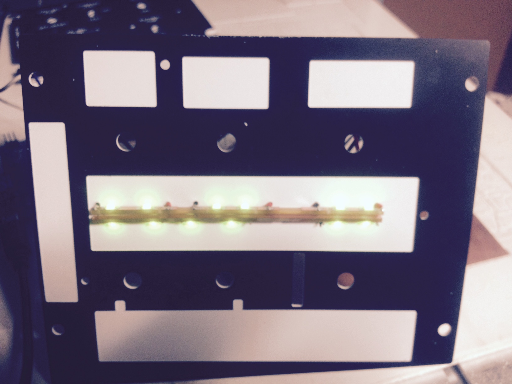
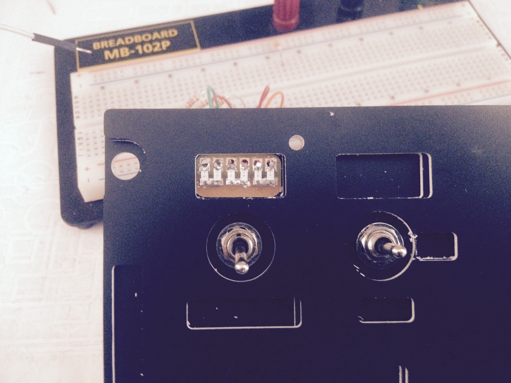
Thanks Guys! I wanted to finish the entire panel to make sure my method would work before posting any details. I have made small sections of PC board with surface mount 0805 leds. The boards are mounted so that leds are not pointing up to the face of the panel but on their side so that they illuminate the pocket that is under the faceplate. Clay
-
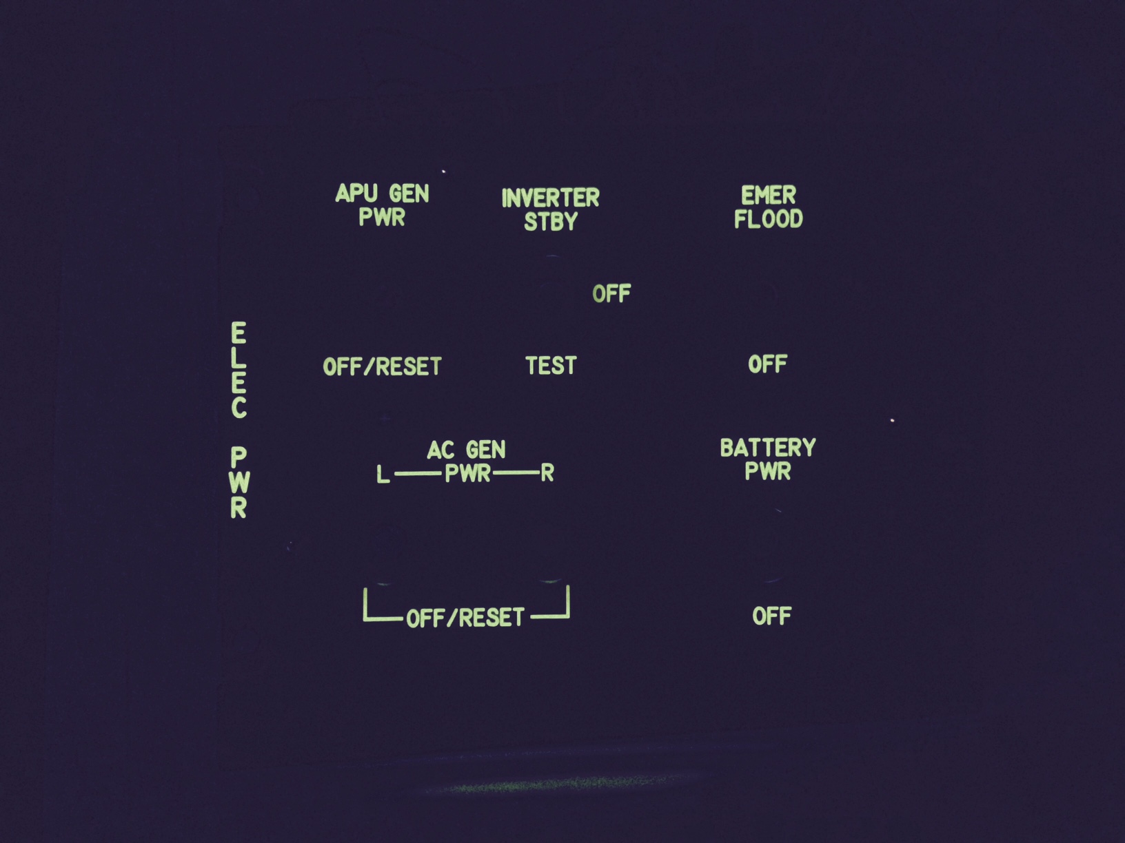
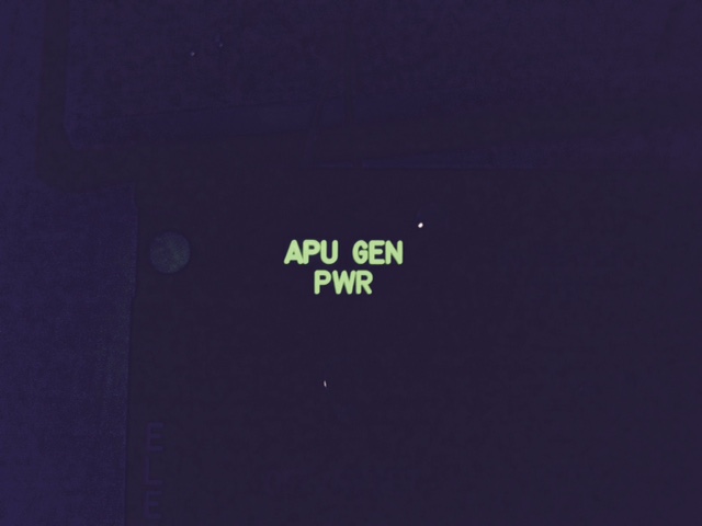
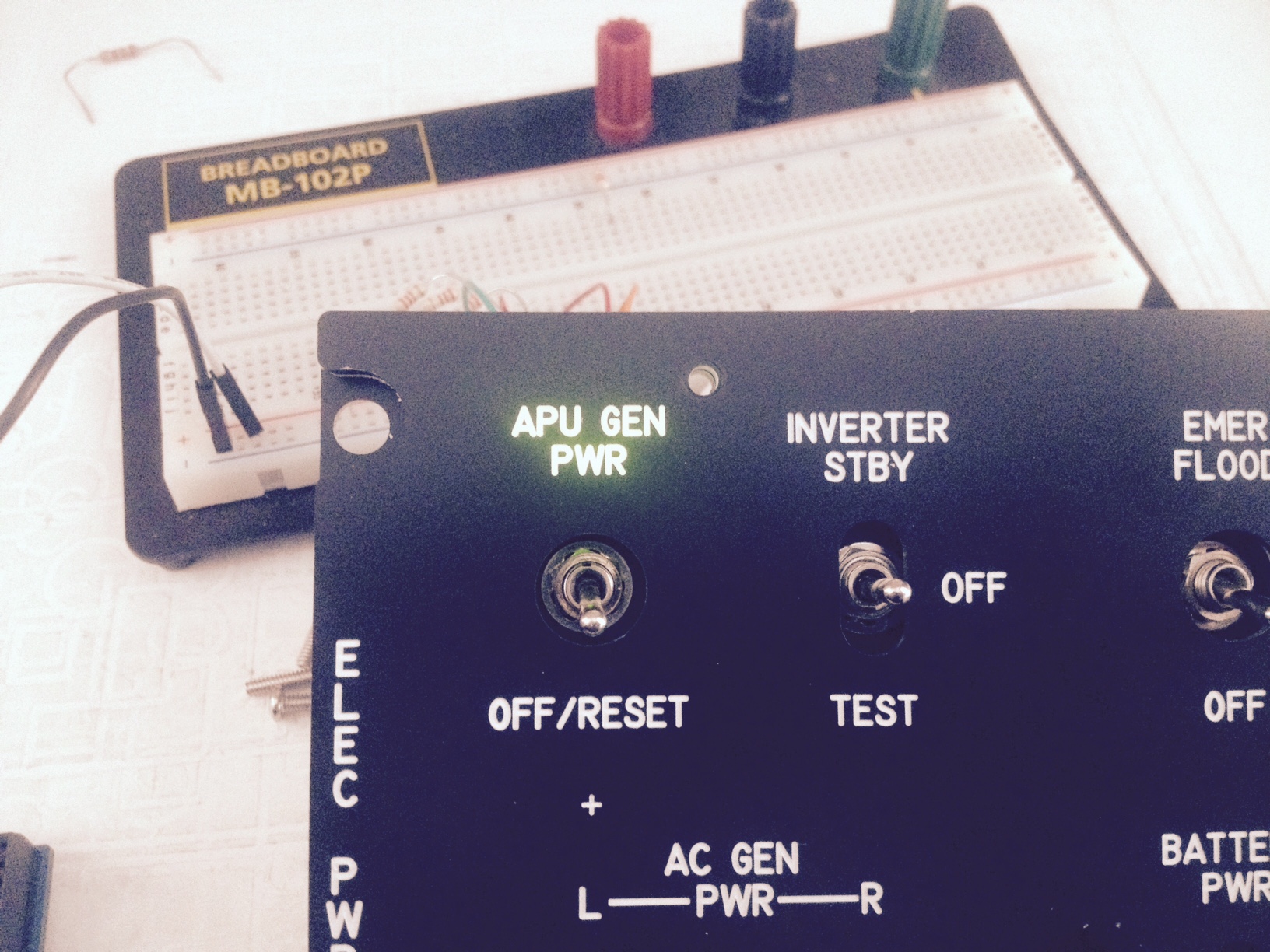
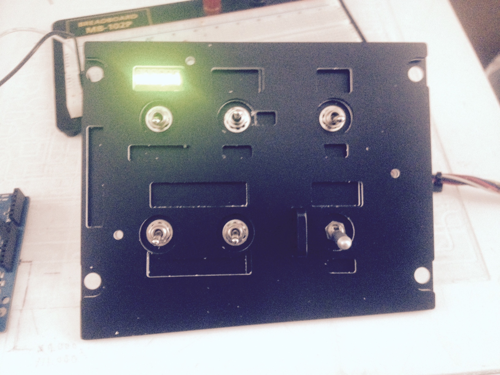
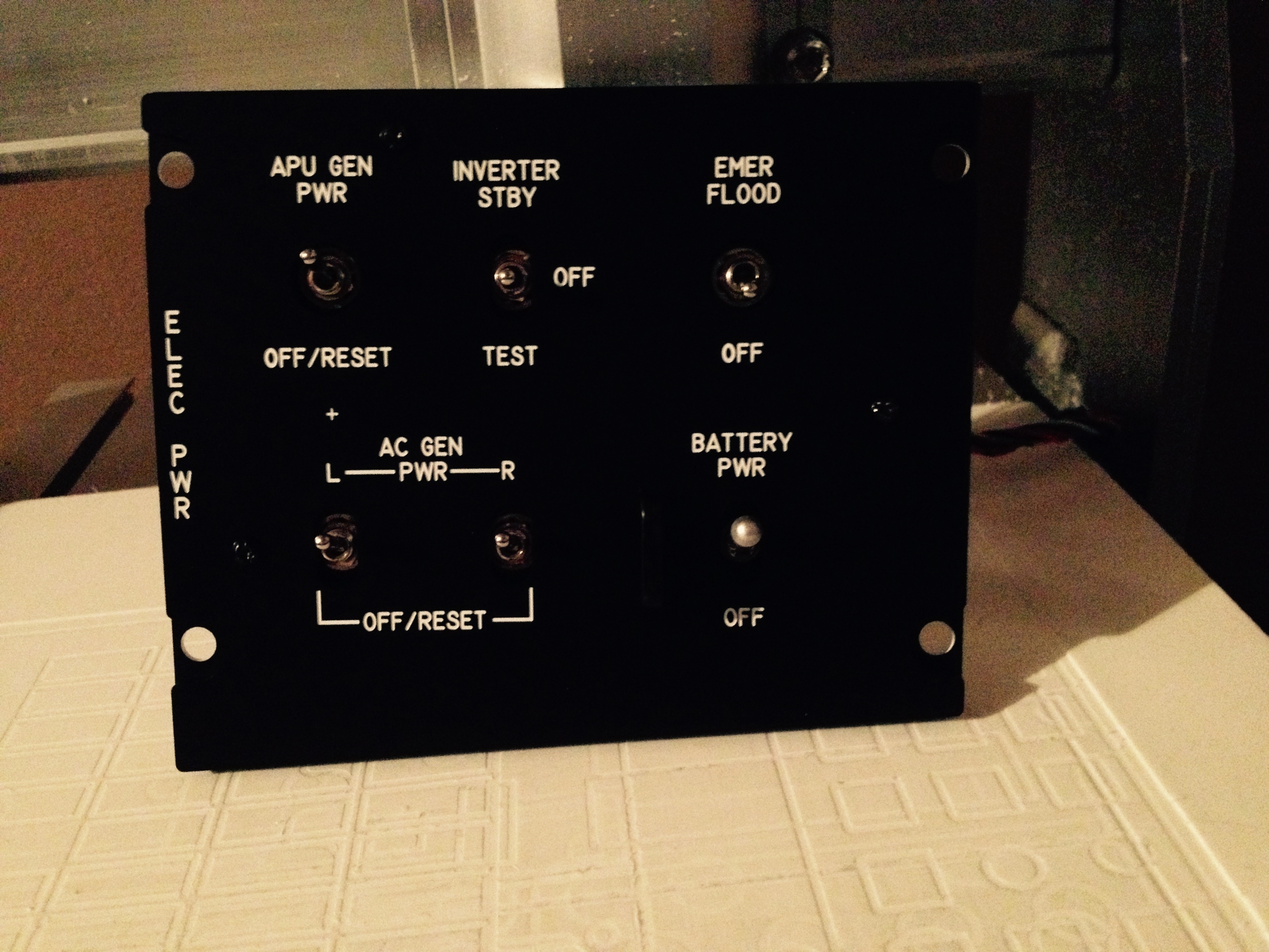
Success! Indirect method seems to be the key! Old Iphone camera sucks. In reality the results are better than what I had hoped. Very consistent light output. Hot spots are absolutely gone. Diffuser not required at all. Looks perfect (to me anyway and that's all that counts really). I just hacked this together for a test but I will take pics of the internals when i clean it up a bit (by that i mean a lot). I have to modify entire panel. Really appreciate all the help offered here guys. For some reason I was stuck on the idea that I had to have lighting directly behind the labels. Big mistake. Huge thanks again Clay
-
Thanks Gadroc! I see my mistakes now. Like Anton hinted at. Move the hot spots away from view and problem solved. I will redesign and try again. Hoping to get this figured out so I can move on to backlighting my Gadroc inspired CMSP panel! I'm sure the push buttons will bring on a new challenge.... Very nice panel by the way! Clay
-
Bravo I have tried diffuser. I doesn't seem to give good results in such a short distance. Since i am trying to keep everything within the thickness of the lightplate I still get hot spots with 1 or 2 leds using diffuser film. Maybe I should try a different product?? Looking forward to seeing how yours turns out! Keep us updated! Anton Are you thinking I should try a more indirect approach? I can relocate LEDs and report back. Thanks! Clay
-
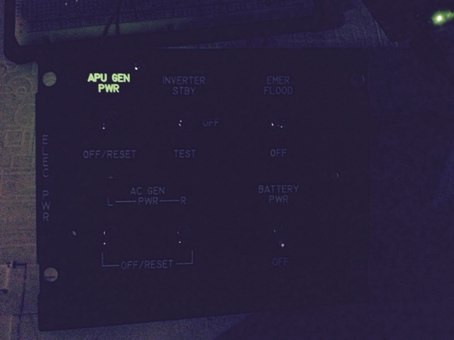
Hi All! Pit progress has come to halt. I have been losing sleep trying to come up with a solution for backlighting. So far here is what I have. Results are OK. Surface mount LEDs on individual PCBs. It will require a lot of wiring and piles of resistors. Obviously to do all panels will require dedicated power supply. Thoughts or advice please. Thanks Clay
-
Sorry, I'm no help here. First thing I have heard about MS stick font! I would love to get my hands on it though. I have had some difficulty finding any stick fonts that I can work with. Clay
-
For some reason, that I don't understand yet, the new font required different settings for the toolpaths to cut correctly. After a lot of "trial and error" I managed to make it work. It is most likely due to my lack of experience with my cam program. So, if I can make it work, ANYBODY can make it work! Also Lars, If it is a big job for you to put everything in one file then DON'T. You have already put a lot effort into this. It is not that hard for us to move things around and create our single file like we want it. I just cut/paste the files to create a single one. Only takes a couple of minutes. So don't trouble yourself. It's just a minor detail. I would much rather you progress with the mip (ufc!) than worry about file structure. Clay
-
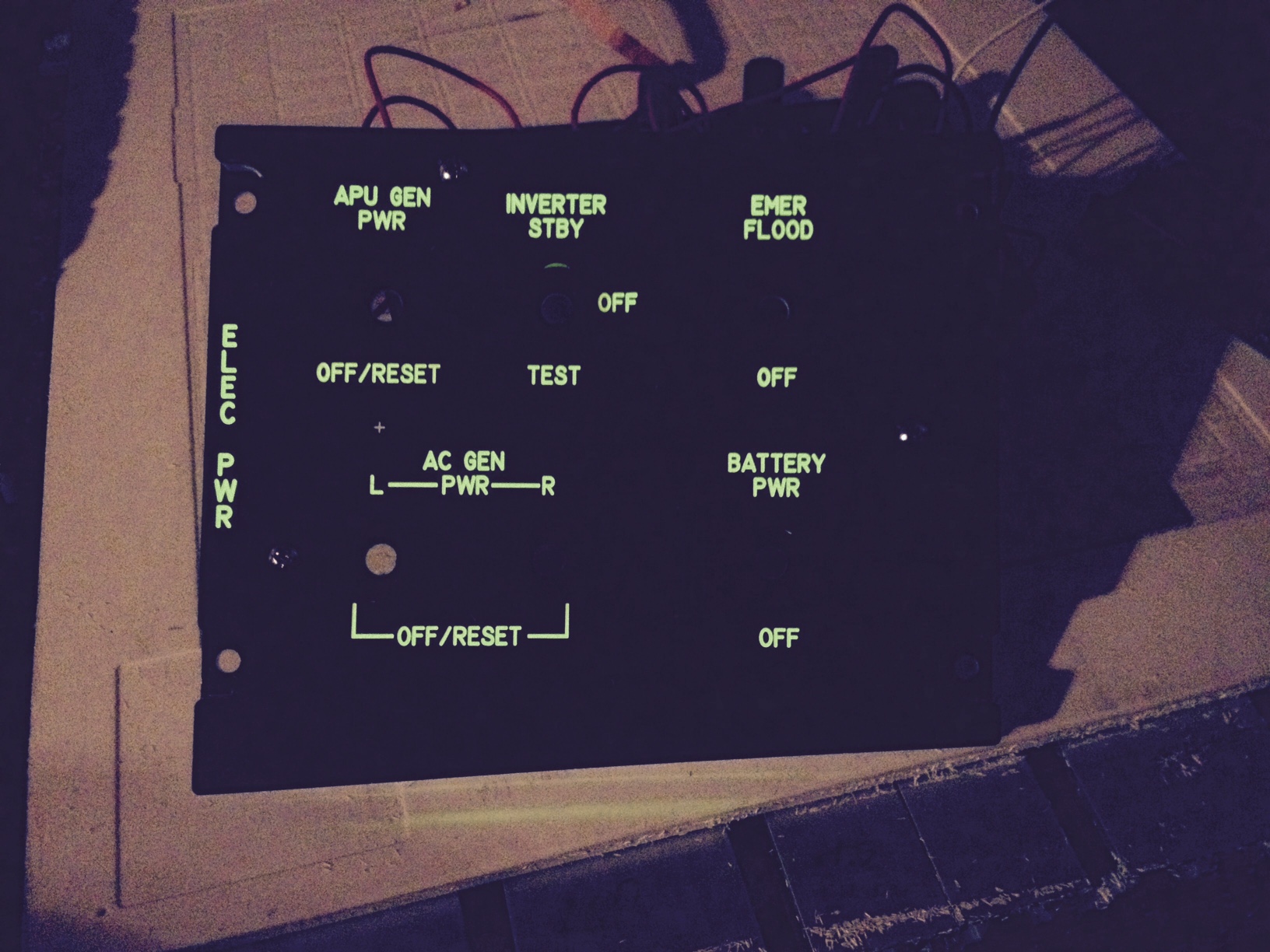
Latest results Everybody agree that this is what it should like? Thanks Lars! Clay
-
Thanks John and Lars I am pocketing because I could not get the stick font installed. I did find a fix though. I changed "region fill style" to outside offsets. I usually use inside+outside. I haven't tried to cut anything yet but will today. Odd how this font cuts requires a bunch of different settings ?? Thanks Guys Clay
-
+1 for merging the three files. Its usually the first thing I do (thanks to Warhog for the idea). But I also change to inch and rotate. I think Anton is correct that nobody expects to have to do no modifications. It only takes a minute and you ( Lars ) have all the needed bits and pieces that need to be there. I am still having some issues. I'm using CamBam and if I use all the same settings I have always used it refuses to make a toolpath in the center horizontal line of the letter B. When I measure that line its .017 thick and I have .010 cutter setup as the tool. If I mess around with stepover it works. ??? Anybody else here use CamBam and run into this? Thanks All! Clay
-
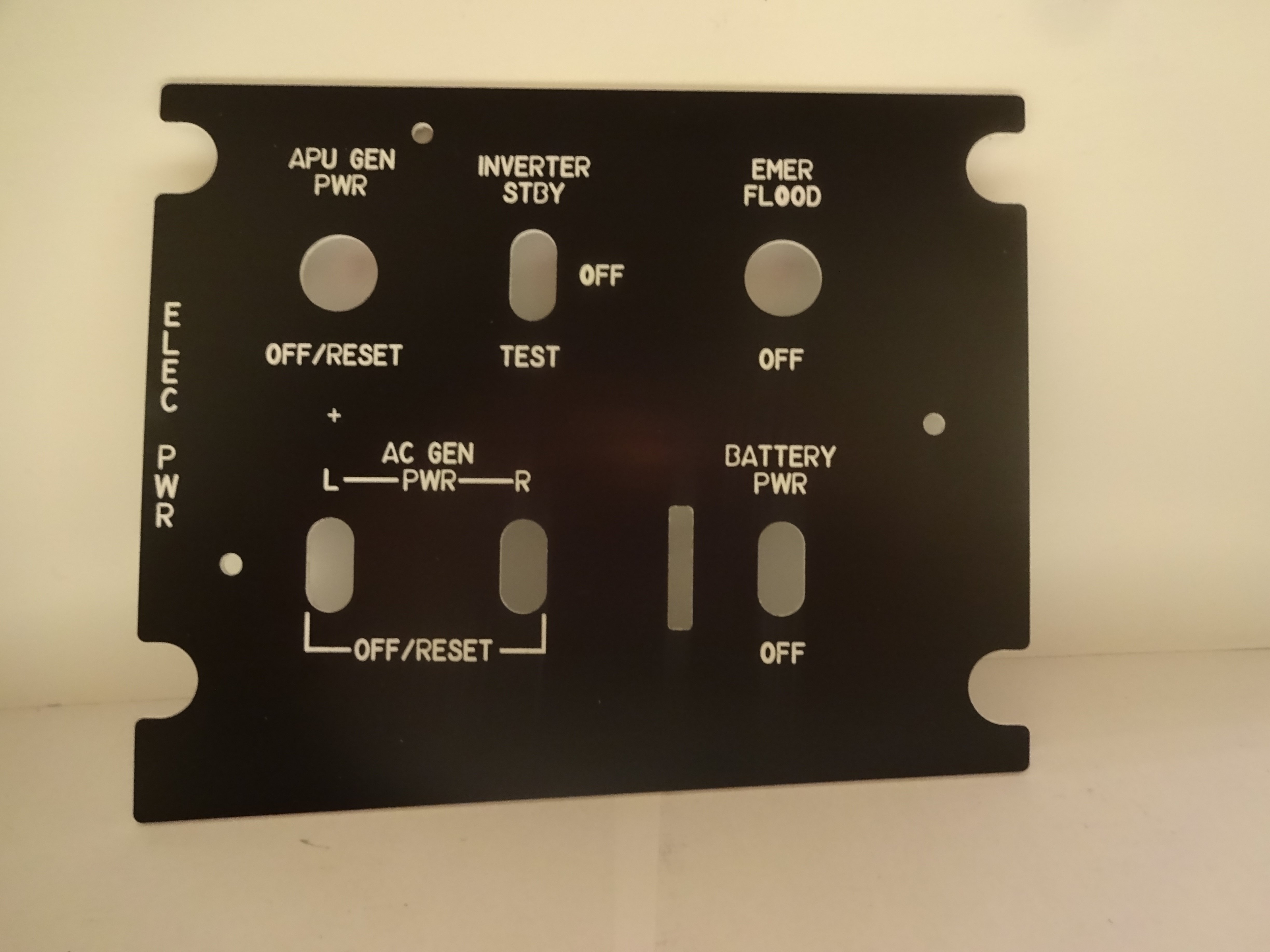
Latest file results As you can see there is some issues. Toolpaths for letter B, R,O and S are not correct. DXF file looks good but cam program produces strange toolpaths. I don'y know why but I am going to try and figure it out . Maybe there is an issue with the font? Anton Thanks for the clarification! I'm still trying to understand the details. Have you tried the MS35588 font? Thanks Clay
-
Lars Latest file works. I will cut now and take pics Clay
-
Greetings Lars This is what I think know so far. Remember I'm new to this and could ,of course, be wrong altogether. .DXF files don't do fonts. When you convert your CAD drawing to .DXF no info on the font is embedded in the file. It doesn't matter if we all have that font installed on our systems. There is nothing in a .DXF file to recognize a font. My understanding is that you have to convert text to polylines in your CAD program before exporting to .DXF. So when I open your current file the text is actually long strings of info about the font details. Maybe someone else has better info for you. Thanks Clay
-
Sorry Lars I forgot to mention that! I wasn't sure but because every other panel has the "OFF" in the center of the switch that must correct. So, yes I did do a little editing. I did have every intention to let you know about it but my mind gets a little scrambled after a long day and staying up too late working on the pit! I was just happy to get it done. Clay