ClayM
-
Posts
147 -
Joined
-
Last visited
Content Type
Profiles
Forums
Events
Everything posted by ClayM
-
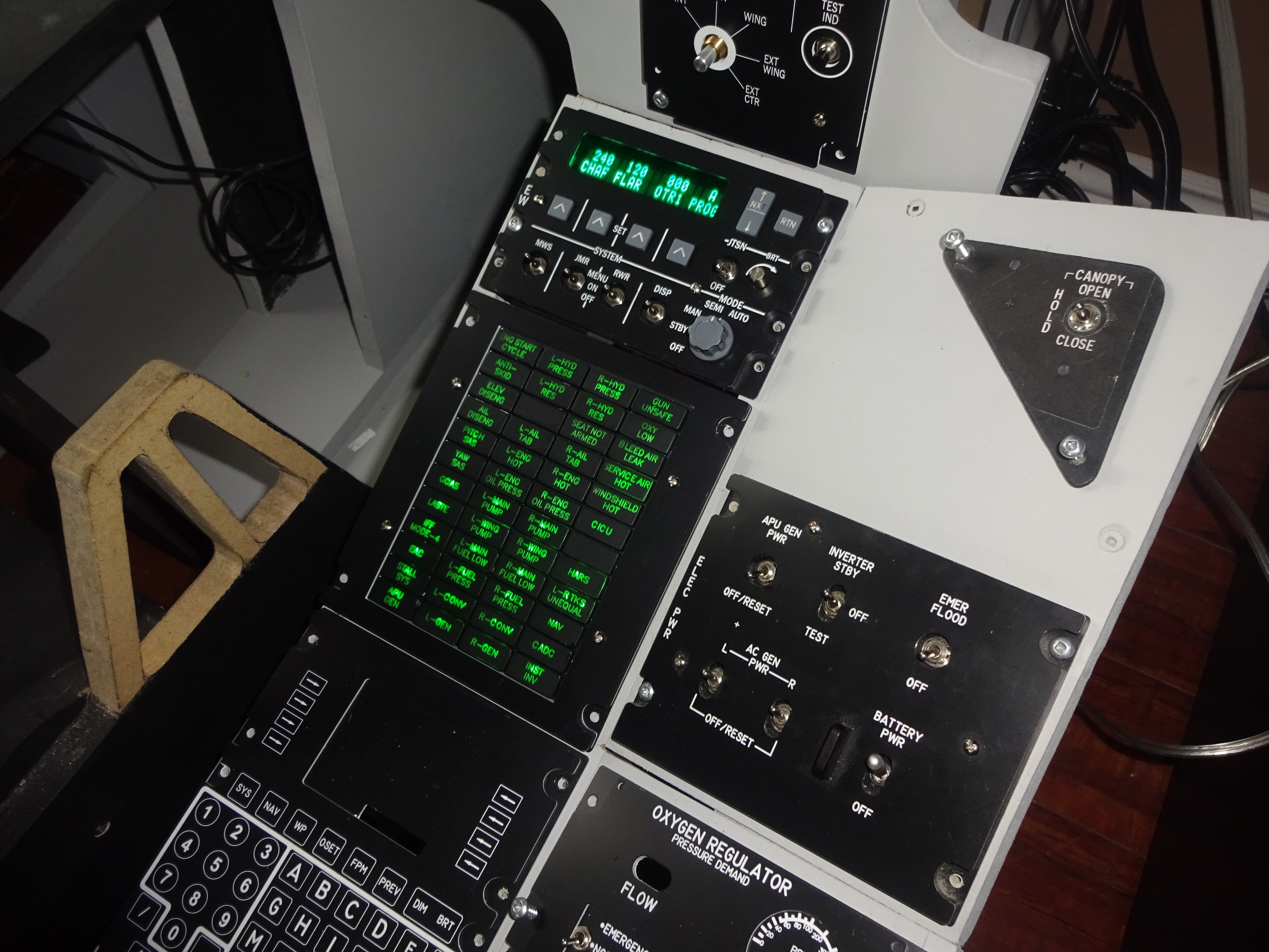
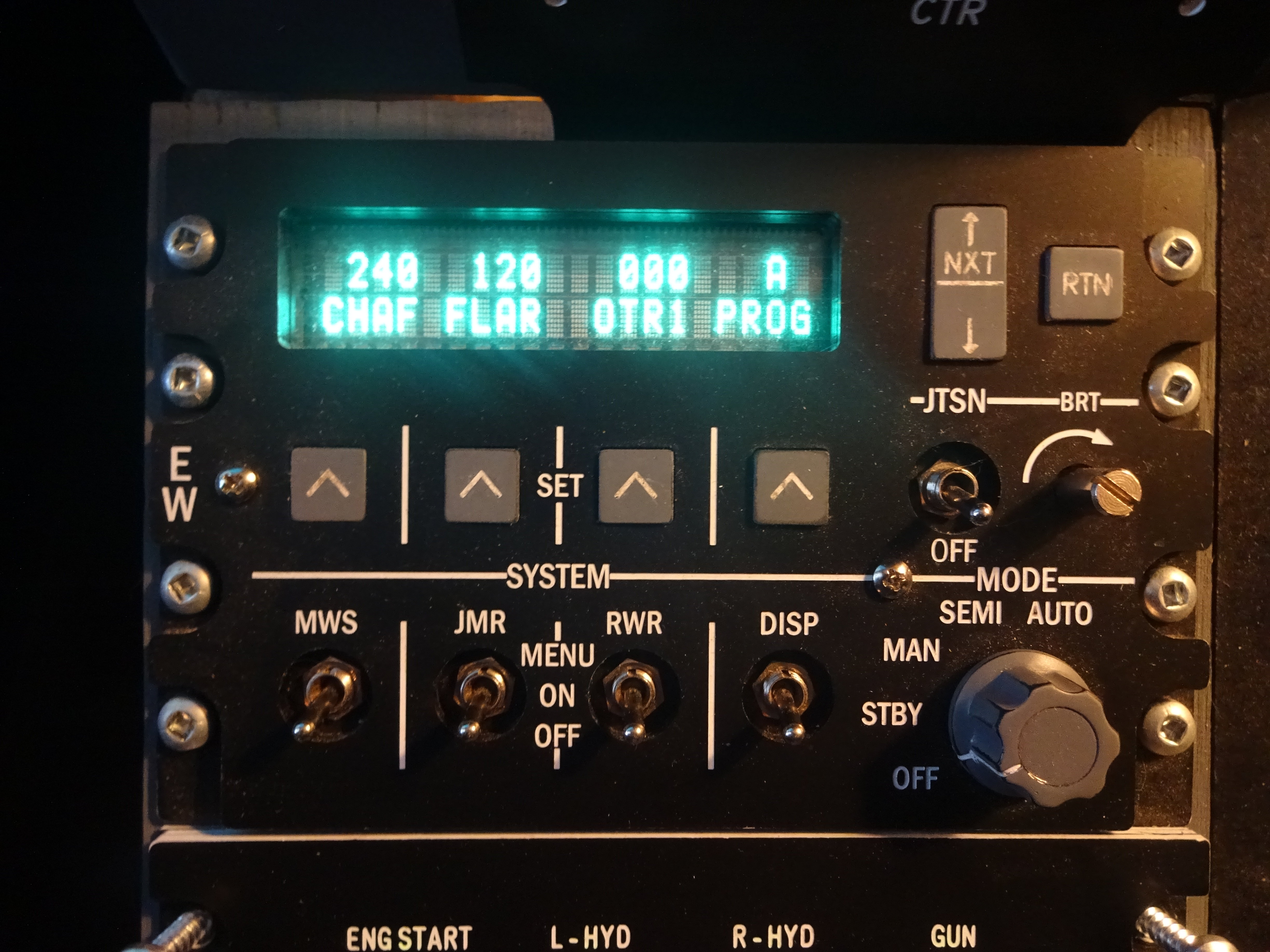
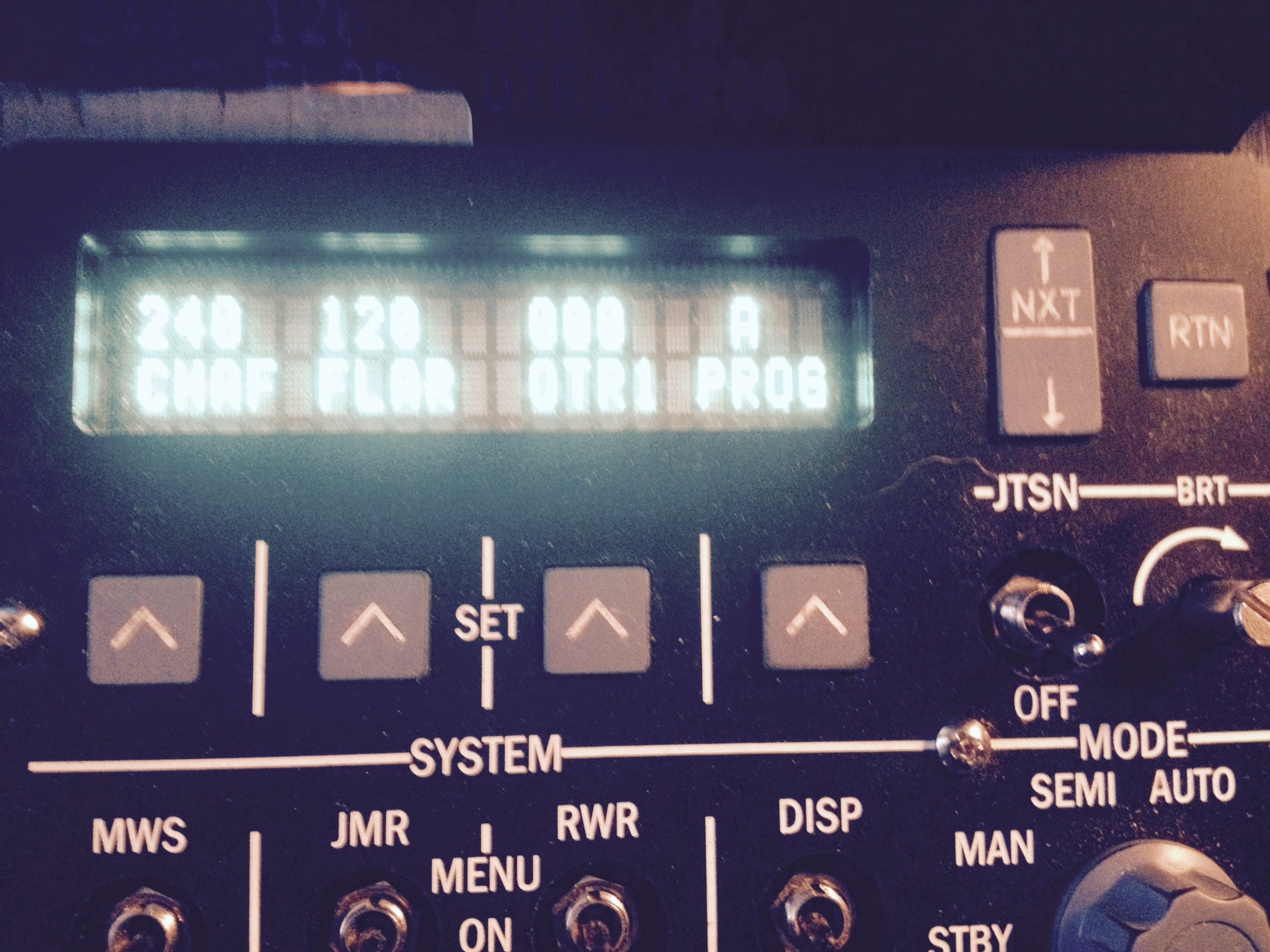
For the CMSP I used a 20x2 Vacuum Flourescent Display. I believe it was a NewHaven Display from Mouser. I added a green lens due to the display being slightly blue color. Its been running for years and still looks great. I could always pull it apart and get some part numbers if needed. ClayM
-
I am stopping work on DCS-BIOS for the foreseeable future
ClayM replied to FSFIan's topic in Home Cockpits
Thanks Ian. Would not been able to do these things without your help, guidance and patience. Good luck Sir Clay -
Congrats John! I know how much work is required to get to where you are. Thanks for helping others while knee deep in your own projects. Don't stop now! Thanks for everything Clay
-
Welcome back RK! Keep posting those updates. I still need seat arm switch also so looking forward to seeing your solution. I guess the key is to get the pivot point right so the linkage goes over center to hold it in the up position if you use a setup like Hans is suggesting. I was thinking of using a ball detent in some way but i think every thing would have to be fairly precise to get nice action. Maybe larger ball/softer spring would be better..... @ Hans Can you please post pics of your setup in the up position also? Those parts look like the real deal!! Thanks Clay
-
How To: DCS-BIOS RS-485 Bus with MAX485-based breakout boards
ClayM replied to FSFIan's topic in Home Cockpits
Ian Can you please explain cabling requirements. Can we just use any two conductor cable for "a" and "b" lines? or should we use shielded twisted pair? if so, should we ground the shield or is it not required? What would be the most reliable/stable method to use? Thanks Clay -
How To: DCS-BIOS RS-485 Bus with MAX485-based breakout boards
ClayM replied to FSFIan's topic in Home Cockpits
Ian Thank you for this. Max485s going in garbage. Max487s on order. Hard to find a reason to use them now. Not worth the effort in my opinion! Thanks for making it simple. Clay -
Nice job on CDU Patriot! I don't think I have ever been happy with the first versions of any my panels. I think my current CMSP panel is version 6. I think your CDU looks great. I find it very hard to decided on font sizes and location until I can see the finished product and decide on what to change. Sometimes I end up changing something and it looks worse! Can you tell me what material you used for the buttons? The backlighting looks great! and PCB! Clay
-
Thanks for the help guys! Patriot This is fantastic! Thanks! I have spent many hours trying move traces around for this PCB. Thankfully there are people here that are smarter then I am:thumbup: I think I understand your code but one question I have is did you calculate the analog input values that you use in your code or just trial and error? John and Hans Thanks for the info! I'm going to order a few of each. See how it goes. Clay
-
Great start to MFD there. Looking forward to seeing it complete one day! I have tried to design the pcb for left mfd myself. I am using 27" monitor so I want connections on left mfd coming out of left side and opposite for the right. so two different pcbs. with encoder at bottom left it reduces number of traces i can fit in that corner so for the left mfd there are too many traces to fit in top right corner. I was thinking of trying to put a small smd multiplexer in top left corner between the rocker switch and button 1. Looks like your using individual screens so solves that problem. Heres pic of my pcb so far. If you had any advice I would greatly appreciate it. And good luck with the rest of your build! Your building great stuff! I'm always watching for your updates. Clay

-
Laz Sorry for the late reply! I have been busy making pcb's and panels! If you are like me and don't want to spend 3 or 4 thousand dollars on a cnc just for pit building then I think 3040 is great. Mine does great on PCB and Panels. Requires a little fine tuning and adjustment. I have 1047 M3's on mine! (M3 is Gcode command for spindle start). Most of those are probably just small tests though.... My opinion is, for under $1000, its good. problems i found where bad assembly by factory. like loose backlash nuts and misaligned gantry. also the bed is not flat. These problems are easily fixed and because it is a fairly small machine the rigidity is ok. I would buy again. My bench! love the Hakko!!
-
Very impressive John! ( I know I have said before....but WOW!) Your work always pushes me to keep going. Looking forward to see some code for that beast. Good luck and hope to see it in action soon. Clay P.S. Lets get some accurate MFDs going next!!
-
pitbldr Thanks very much for the info! Bad news for me. Looks like I made my indicators too high so my panel is one unit too high! Looks like its back to the drawing board...... Thanks again for dimensions! Clay
-
Thanks Ian! Changed sketch to include void setup() DcsBios::setup(); //use only one of the following memset lines uncomment your choice //use this line to set all indicators to on at power up //memset(max7219_rows, 0xff, sizeof(max7219_rows)); //use this line to set all indicators to off at power up memset(max7219_rows, 0x00, sizeof(max7219_rows)); lc.shutdown(0,false); //turn on the display lc.setIntensity(0,15);//set the brightness lc.clearDisplay(0); //clear rthe display and get ready for new data } I agree that all on at power up can be useful. For taking pictures! And confirmed all works as intended! Thanks I posted a pic at pitbldrs thread. His recently posted dimensions means my panel is wrong. His thread has great info for CLP!
-
I'm a bit confused by my latest project. I have built a new caution light panel to replace my old version. It took a couple of months so I don't recall if my old CLP had the same behavior but now as soon I power up the arduino all the LEDs default to ON. Once I start a mission everything works perfectly. I don't remember my old panel doing this and I thought i was using the same sketch (but I have been wrong before!). Here's the sketch (Ian's work. I do not take any credit) #define DCSBIOS_IRQ_SERIAL #include <LedControl.h> #include <DcsBios.h> //pin 10 is connected to the DataIn //pin 11 is connected to the CLK //pin 12 is connected to LOAD LedControl lc=LedControl(12,11,10,1);//DIN,CLK,LOAD,# OF IC's DcsBios::ProtocolParser parser; void loop() { DcsBios::loop(); unsigned char cl_row_map[48] = { 0, 0, 0, 0, 1, 1, 1, 1, 2, 2, 2, 2, 3, 3, 3, 3, 4, 4, 4, 4, 5, 5, 5, 5, 0, 0, 0, 0, 1, 1, 1, 1, 2, 2, 2, 2, 3, 3, 3, 3, 4, 4, 4, 4, 5, 5, 5, 5 }; #define SEG_DP (1<<7) #define SEG_A (1<<6) #define SEG_B (1<<5) #define SEG_C (1<<4) #define SEG_D (1<<3) #define SEG_E (1<<2) #define SEG_F (1<<1) #define SEG_G (1<<0) unsigned char cl_mask_map[48]= { SEG_DP, SEG_B, SEG_D, SEG_F, SEG_DP, SEG_B, SEG_D, SEG_F, SEG_DP, SEG_B, SEG_D, SEG_F, SEG_DP, SEG_B, SEG_D, SEG_F, SEG_DP, SEG_B, SEG_D, SEG_F, SEG_DP, SEG_B, SEG_D, SEG_F, SEG_A, SEG_C, SEG_E, SEG_G, SEG_A, SEG_C, SEG_E, SEG_G, SEG_A, SEG_C, SEG_E, SEG_G, SEG_A, SEG_C, SEG_E, SEG_G, SEG_A, SEG_C, SEG_E, SEG_G, SEG_A, SEG_C, SEG_E, SEG_G }; unsigned char max7219_rows[8]; void setup() DcsBios::setup(); memset(max7219_rows, 0xff, sizeof(max7219_rows)); lc.shutdown(0,false); //turn on the display lc.setIntensity(0,15);//set the brightness lc.clearDisplay(0); //clear rthe display and get ready for new data } void updateCautionLights(unsigned int address, unsigned int data) { unsigned char clp_row = (address - 0x10d4) * 2; unsigned char start_index = clp_row * 4; unsigned char column = 0; unsigned char i; bool is_on; for (i=0; i<16; i++) { is_on = data & 0x01; // set caution light state (clp_row, column, is_on) if (is_on) { max7219_rows[cl_row_map[start_index+i]] |= cl_mask_map[start_index+i]; } else { max7219_rows[cl_row_map[start_index+i]] &= ~(cl_mask_map[start_index+i]); } data >>= 1; column++; if (column == 4) { clp_row++; column = 0; } } } void onDcsBiosWrite(unsigned int address, unsigned int data) { if (address >= 0x10d4 && address <= 0x10d8) { updateCautionLights(address, data); } if (address == 0xfffe) { // update MAX7219 unsigned char i; for (i=0; i<8; i++) { lc.setRow(0, i, max7219_rows[i]); } } } I have read the MAX7219 datasheet and the only thing I came up with was changing lc.clearDisplay to 1 which,in the end, made no difference. Is there a way to make leds default to off on power up? Thanks!
-
+1 on that! Looks great RK! Keep it up! ClayM
-
Thanks Brewnix! @DM Really?? your statement "I am not really sure what your point it or how it is a reply to previous post." Now you know why you get no feedback. I should have known better.:doh:
-
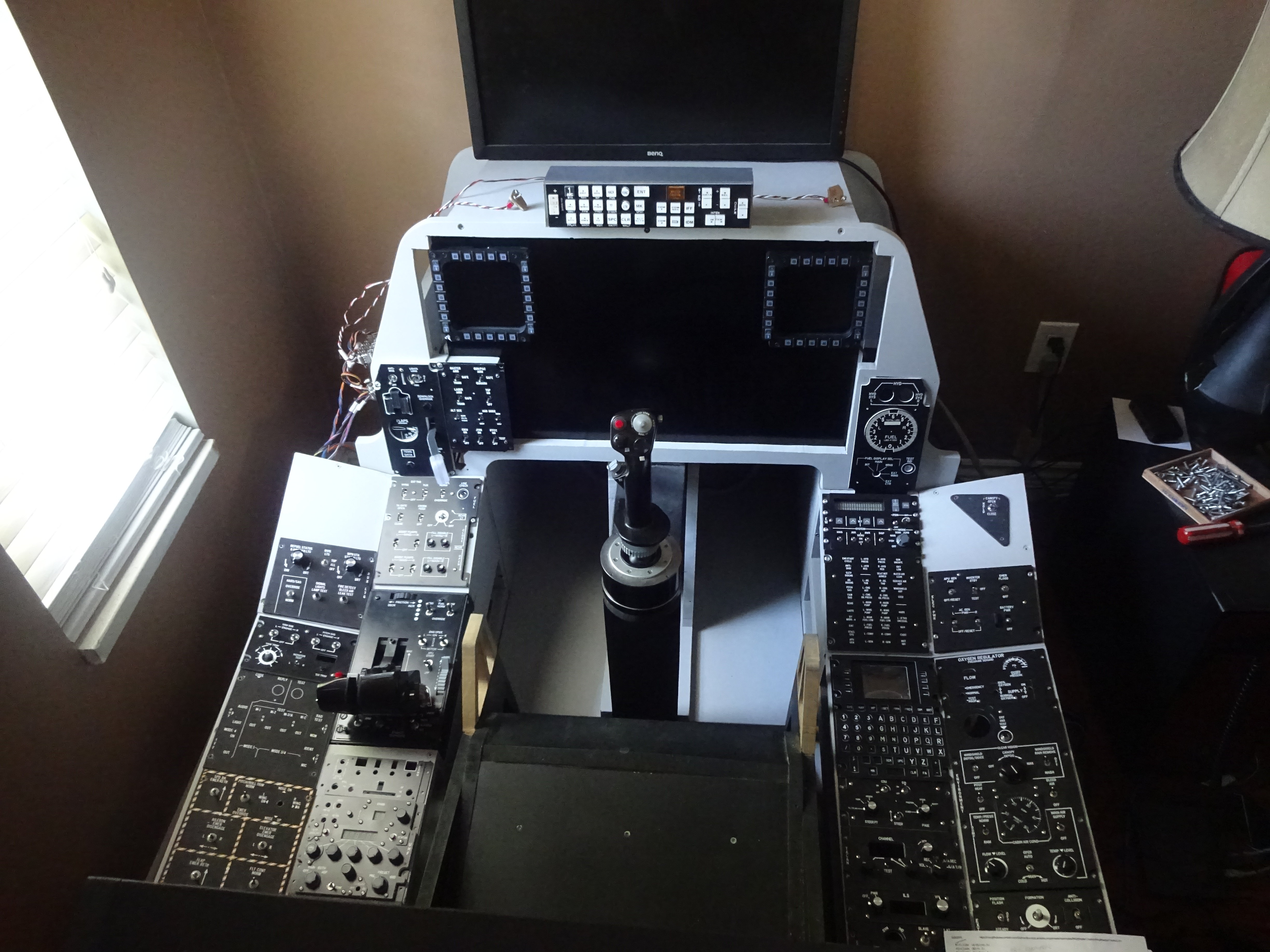
DM I'm not sure if you consider me a member of the "cockpit builder" group or not but I am going to give you some feedback/opinions anyways. I have attached a pic of my work in progress pit so you can decide if I qualify. First, Congrats to all that had a hand in this. Great design and implementation. Well Done! If I was building and using my pit in a heated garage with an 8' foot door I would be building it right now. I have to build my pit inside the house through two doorways and around a corner. For me ( and only an opinion not criticism ) a pit must somehow be able to breakdown enough to get through a 36" doorway. Sorry, but I cannot commit to trapping my pit in a room. My wife may kick me out of the house at anytime because of the pit! I need to at least be able to take it with me! With Dimebugs pit I just take out 4 screws and unplug a couple USB cables and one DB9 connector and I can pull out a side console. It takes two guys to lift MIP but I can have it all in the back of my pickup in less than an hour. Bring a bag of screws and one screwdriver and put her all back together again anywhere I want. I get the fact that I am lacking a lot of elements,especially the canopy bow, but sometimes we need to compromise. Maybe one day my situation will change. Just my 2 cents. Clay
-
John I don't think I have any interference issues. I did have issues with switch bounce on my cheap tactile's. They would occasionally give me two presses. I added 100 ms delay (as suggested by Ian) in all my sketches and now things like UFC function perfectly. I guess this could have been some kind of cross talk or interference but its a non issue now. I have seen your new stick gimbal! good luck! I'm excited to see what your insanity comes up with next. Keep it up! Clay
-
Thanks Hans! I didn't think to try the centipede library. I will give it shot! Coming up with new code on my own has not been going well but modifying existing code is getting easier. Thanks for giving me something to start with. I'll report back with results. @ Warhog I get the pin count problem. I also realize it would be "cool" to have self contained panels. For me that sounded way to difficult. That is why (so far) I went with the centralized controller concept. For example my one left console mega handles the AHCP,L/G panel with the servo and indicators,fuel panel,aux ltg,sas and the day/night switchs for mfds. Its my easy way to do it I guess. It just makes for a hell of a lot wire running everywhere! On the right console is another mega that takes care of CMSP i/o(not the display though) canopy,elec pwr,oxy,aap,and some misc like pitot heat and anti-collision lights. So with just 2 mega's using only 2 usb ports I managed to take care of most of the simple panels. The backlighting is all independent using your idea with pwm drivers mounted in the ext/int lighting panel. I'm not saying my way is better. I requires a LOT of wire and plugs but not as many custom pcb's. The problem I have is that as soon as I use a Nano or Promini I have to do RS485 also. So there is the added design and parts and cnc and copper clad board and sockets and....... Wife says I have to cut the grass. Gotta go!:( Thanks Guys! Clay
-
Greetings John! Hope your feeling better! Pit progress seems to be getting slower and slower as the level of difficulty is getting higher. It has taken me 2 weeks to build the landing gear indicators and I'm still not thrilled with them. They stick out of the panel too far in my opinion so back to the drawing board(again). Also the back lighting for the panels is slowing me down a lot. On top of all that I spent a couple weeks trying out some ideas for correct sized MFCDs. The size of the thrustmasters has always bothered me. Especially that giant radius they have on the inside of the frames. I put those on hold until I see what Lynx comes up with. Reasoning behind the MCP23017s is that I already have these built. I used them with helios and eos bus from gadroc. I used Uno R3s and the proto shields. On each shield I have one MCP23017 and one max485 (they are on sockets so i can change to max487 easily). Also I can change out the 23017 to a max7219 if need to. I was just trying to use up some of my existing gear. They are really easy to build with no custom pcb and give you lots of I/O. But i have to agree with you. I have couple of pro minis I haven't used yet. I guess its time to give them a shot. My goal right now is to get the cmsp fully functional and use the max 487. No more pics yet. I hacked up my MIP to fit a new 27" monitor so I need to do some repairs first! So your idea is for me to make custom PCB to mount two prominis and two max487 thus allowing me to use the simple DCS-Bios code? Have you found you can just use a standard board for most panels and using two if required? or is there too many variables to make that work. I have my UHF panel on a mega right now due to so many pins required for the encoders. I havent even started VHFs yet. So much left to do....... Thanks Clay
-
Trying to get the MCP23017 working with DCS-Bios. I'm starting to understand some of the concepts but still a lot to learn! I tried this but no luck. Compiles fine but....nothing works /* Tell DCS-BIOS to use a serial connection and use the default Arduino Serial library. This will work on the vast majority of Arduino-compatible boards, but you can get corrupted data if you have too many or too slow outputs (e.g. when you have multiple character displays), because the receive buffer can fill up if the sketch spends too much time updating them. If you can, use the IRQ Serial connection instead. */ #define DCSBIOS_DEFAULT_SERIAL #include "DcsBios.h" #include "Wire.h" // Use the Wire Library for I2C byte a=0; // Variable to store the Byte in /* paste code snippets from the reference documentation here */ DcsBios::Switch2Pos cmspArw1("CMSP_ARW1", byte(1)); void setup() { DcsBios::setup(); Wire.begin(); // wake up I2C bus Wire.beginTransmission(0x20); // Connect to chip Wire.write((byte)0x01); // Select Bank B Wire.write((byte)0x00); // Set all of bank B to outputs Wire.endTransmission(); // Close connection } void loop() { DcsBios::loop(); // Read the inputs of bank A Wire.beginTransmission(0x20); // Connect to chip Wire.write(0x12); // Set Memory Pointer to Bank A Wire.endTransmission(); // Close connection Wire.requestFrom(0x20, 1); // Request one Byte a=Wire.read(); // Put the Byte into variable 'a' // Write the Byte to Bank B //Wire.beginTransmission(0x20); // Connect to chip //Wire.write(0x13); // Set Memory Pointer to Bank B //Wire.write(a); // Write the Byte //Wire.endTransmission(); // Close connection delay(50); // Small delay to debounce switch } The "byte a=0" has me confused. I did expect to see some output but got nothing! Hmm... I also messed around with the Adafruit MCP23017 library but could not make sense of using it for inputs. Thanks Clay
-
Actually this is better #define DCSBIOS_IRQ_SERIAL #include "DcsBios.h" #include <LiquidCrystal.h> LiquidCrystal lcd(12, 11, 5, 4, 3, 2); void onCmsp1Change(char* newValue) { lcd.setCursor(0, 0); lcd.write(newValue[9]); lcd.write(newValue[0]); lcd.write(newValue[1]); lcd.write(newValue[2]); lcd.write(newValue[3]); lcd.write(newValue[4]); lcd.write(newValue[5]); lcd.write(newValue[6]); lcd.write(newValue[7]); lcd.write(newValue[8]); lcd.write(newValue[9]); lcd.write(newValue[9]); lcd.write(newValue[10]); lcd.write(newValue[11]); lcd.write(newValue[12]); lcd.write(newValue[13]); lcd.write(newValue[14]); lcd.write(newValue[15]); lcd.write(newValue[16]); lcd.write(newValue[17]); lcd.write(newValue[18]); lcd.write(newValue[19]); } DcsBios::StringBuffer<19> cmsp1Buffer(0x1000, onCmsp1Change); void onCmsp2Change(char* newValue) { lcd.setCursor(0, 1); lcd.write(newValue[0]); lcd.write(newValue[1]); lcd.write(newValue[2]); lcd.write(newValue[3]); lcd.write(newValue[4]); lcd.write(newValue[5]); lcd.write(newValue[6]); lcd.write(newValue[7]); lcd.write(newValue[8]); lcd.write(newValue[9]); lcd.write(newValue[9]); lcd.write(newValue[10]); lcd.write(newValue[11]); lcd.write(newValue[12]); lcd.write(newValue[13]); lcd.write(newValue[14]); lcd.write(newValue[15]); lcd.write(newValue[16]); lcd.write(newValue[17]); lcd.write(newValue[18]); lcd.write(newValue[19]); } DcsBios::StringBuffer<19> cmsp2Buffer(0x1014, onCmsp2Change); void setup() { DcsBios::setup(); lcd.begin(20, 2); lcd.clear(); } void loop() { DcsBios::loop(); } Moved top CMSP line right by 1. Clay
-
Thanks Ian! I re-read previous posts and figured out what I was doing wrong. I was thinking the value after "newValue" was position when in fact it is data! This code works and has the positions where I want them. #define DCSBIOS_DEFAULT_SERIAL #include "DcsBios.h" #include <LiquidCrystal.h> LiquidCrystal lcd(12, 11, 5, 4, 3, 2); void onCmsp1Change(char* newValue) { lcd.setCursor(0, 0); lcd.write(newValue[0]); lcd.write(newValue[1]); lcd.write(newValue[2]); lcd.write(newValue[3]); lcd.write(newValue[4]); lcd.write(newValue[5]); lcd.write(newValue[6]); lcd.write(newValue[7]); lcd.write(newValue[8]); lcd.write(newValue[9]); lcd.write(newValue[9]); lcd.write(newValue[10]); lcd.write(newValue[11]); lcd.write(newValue[12]); lcd.write(newValue[13]); lcd.write(newValue[14]); lcd.write(newValue[15]); lcd.write(newValue[16]); lcd.write(newValue[17]); lcd.write(newValue[18]); lcd.write(newValue[19]); } DcsBios::StringBuffer<19> cmsp1Buffer(0x1000, onCmsp1Change); void onCmsp2Change(char* newValue) { lcd.setCursor(0, 1); lcd.write(newValue[0]); lcd.write(newValue[1]); lcd.write(newValue[2]); lcd.write(newValue[3]); lcd.write(newValue[4]); lcd.write(newValue[5]); lcd.write(newValue[6]); lcd.write(newValue[7]); lcd.write(newValue[8]); lcd.write(newValue[9]); lcd.write(newValue[9]); lcd.write(newValue[10]); lcd.write(newValue[11]); lcd.write(newValue[12]); lcd.write(newValue[13]); lcd.write(newValue[14]); lcd.write(newValue[15]); lcd.write(newValue[16]); lcd.write(newValue[17]); lcd.write(newValue[18]); lcd.write(newValue[19]); } DcsBios::StringBuffer<19> cmsp2Buffer(0x1014, onCmsp2Change); void setup() { DcsBios::setup(); lcd.begin(20, 2); lcd.clear(); } void loop() { DcsBios::loop(); } Thanks! Clay
-
While we are on the topic of the CMSP I had a question also. I am using 20 x 2 display. Both lines of lcd.setcursor is 0. But 19 character string starts in the 1 position. [ATTACH]143093[/ATTACH] (sorry... cel phone pic again) Is it possible to move chaff and flare left by one thus adding a space between FLAR and OTR? It would make the alignment better in my opinion. I guess this is something inside DCS-Bios that starts 19 char string at 1. Not a big deal though. Still works great but I cant move the display anymore to left without poking through the frame! Thanks for help ClayM
-
Thank you Hans! I actually built this panel some time ago. I have since changed the font for my panels which should be a closer copy of your pic. Now I have to go back and re-do a bunch of my old panels! Mr_Burns Yes. If I understand you correctly that should work great! I have to admit that building backlit panels has been a big challenge for me. Building basic panels, even with displays or indicators is one thing but trying to backlight an entire panel plus the pushbuttons, is a totally differant story. I am now thinking that using copper clad board for the base plate might be the best thing to do. It would make backlighting so much easier. I'm going to give it try and post the results. Clay