ClayM
-
Posts
147 -
Joined
-
Last visited
Content Type
Profiles
Forums
Events
Everything posted by ClayM
-
Latest attempt. I know the 1/4" switches need to go. When I do the change to aluminum backplates I will go for accurate switches. But for now they function just fine and I'm still at proof of concept stage. Clay

-
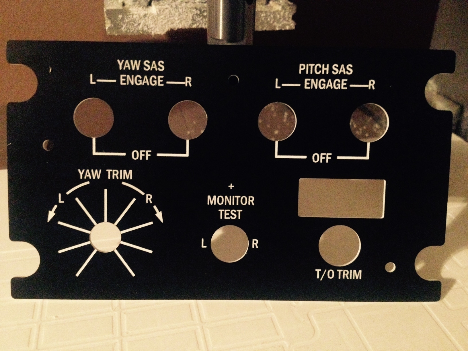
Cut CMSP again Looks much better. Used the exact same settings. Changed NOTHING! Set my z zero based on advice from Warhog. So operator error on the last one. Thanks Lars and John! Clay
-
John If you compare the CMSP and SAS pics how much error in Z height would you guess it is off by? Assuming same 60 degree .010" cutter. Realistically I think I must be + - .001" at the worst. Wouldn't it take 2 or 3 thou at least to have that much effect on line thickness? Thanks Clay
-
Lars Cut SAS last night. You were thinking the text on my CMSP was a little thick. As you can see SAS turned out great with thinner lines. So ,if you have the same font in all your panels, I did something wrong on the CMSP. Possibly cut a little too deep?? Not sure. When I have some time I will cut CMSP again making sure I use same settings as SAS ( which I thought I did ) and let you know what happens. Thanks Clay
-
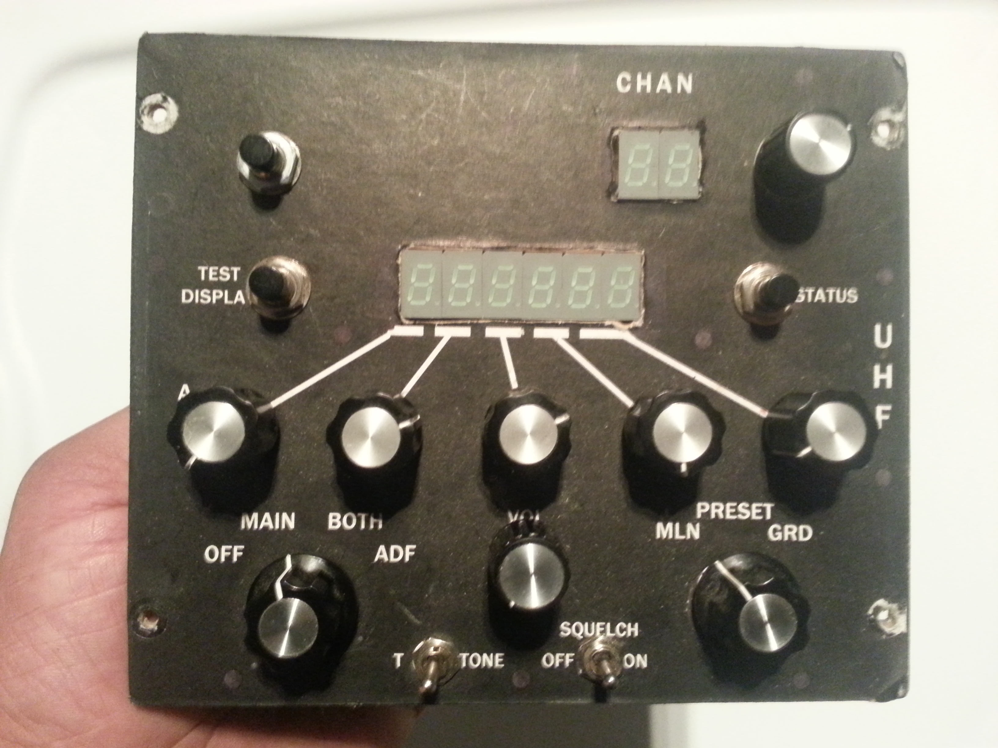
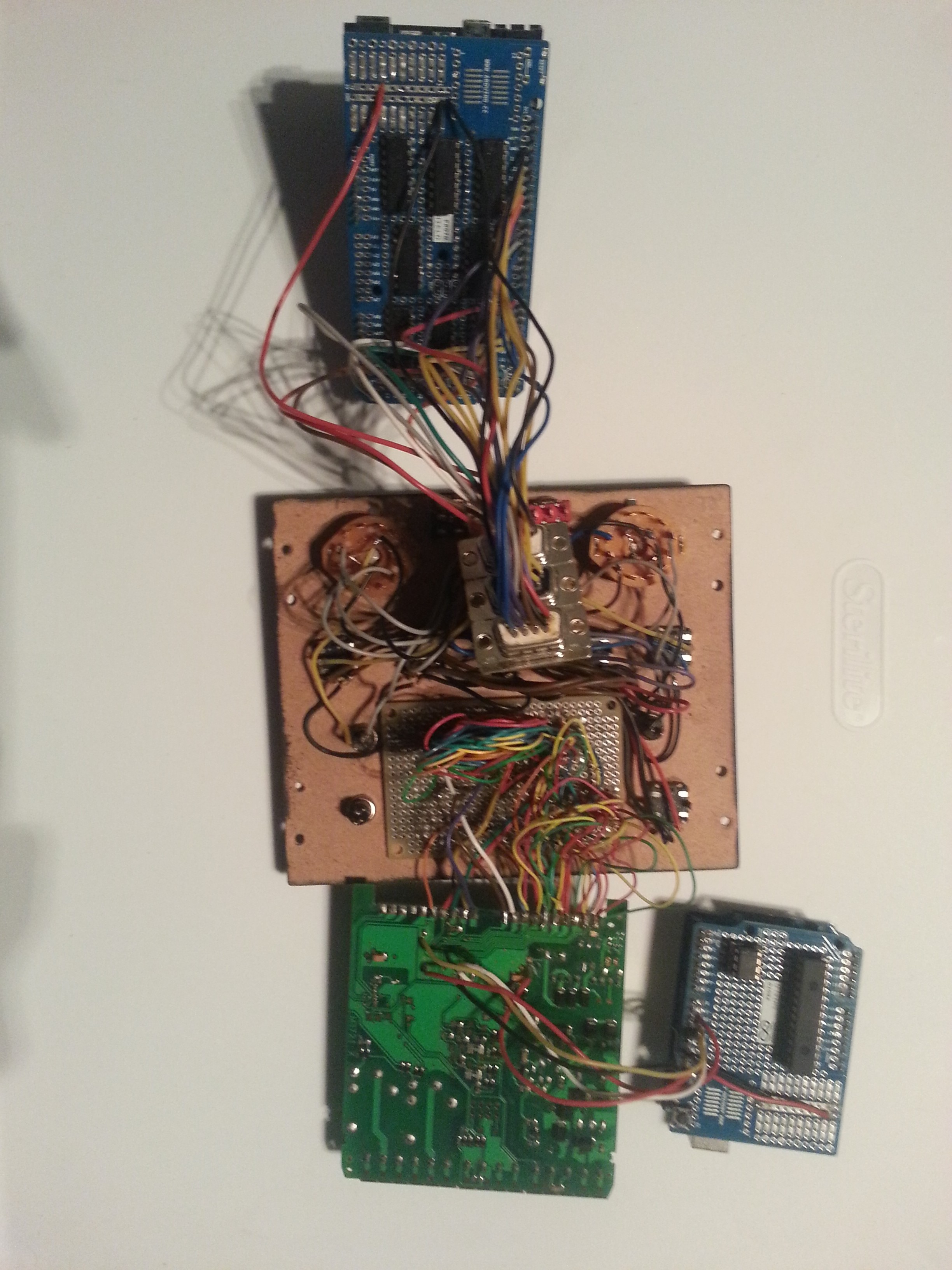
OR now that I can CNC some parts I should probably clean up my UHF. In its current state I must have 200 hours into it! First attempt was SN7407 drivers with individual resistors to run 7 segs. If you think its spaghetti now you should have seen it before I changed to MAX7219. Clay
-
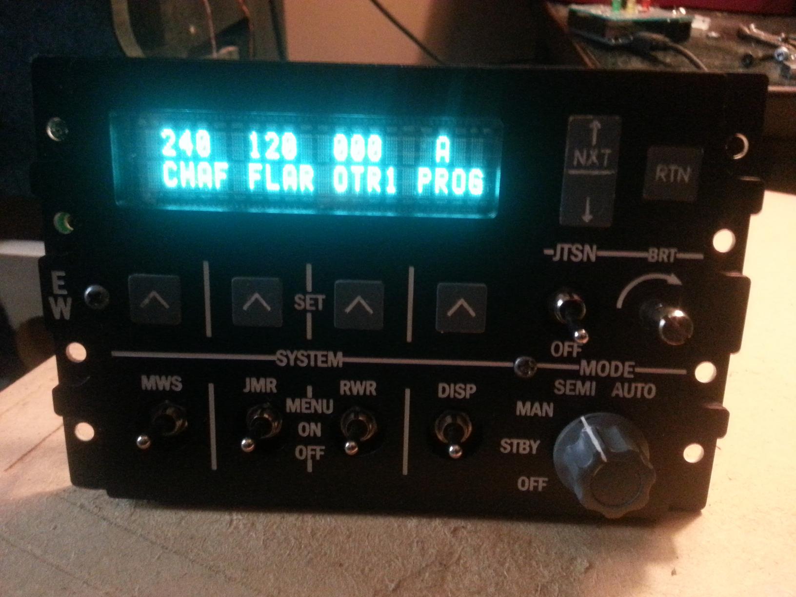
Thanks John! I thought the VFD had a more realistic look than other displays. I originally had green backlight lcd with black text and it just did not look right. Eventually I would like to shift the digits one space to the left. I am going to tear apart CMSP now and cut some pockets for backlighting. Should be an interesting task. I dont even know where im going to get the power from yet. Thinking old PC power supply. And good luck with your CMSC project! Clay
-
Lynx http://www.digikey.ca/product-detail/en/M0220SD-202SDAR1/M0220SD-202SDAR1-ND/1739773 For some reason pictures make display look blue. It actually looks green. The display is driven by its own program that Ian( FSFIan) wrote some time ago. I have it running from its own arduino uno that only handles the display. Works great but at some point I am going to integrate it with the arduino mega that i have controlling the switches and pots with DCSBios. Clay
-
Thanks for the kind comments! This is made from multiple layers of 2 color plastic sheets 1/16" thick. I have cheap made in china 3040 cnc. Works good with plastic. Not so well in metal! Clay
-
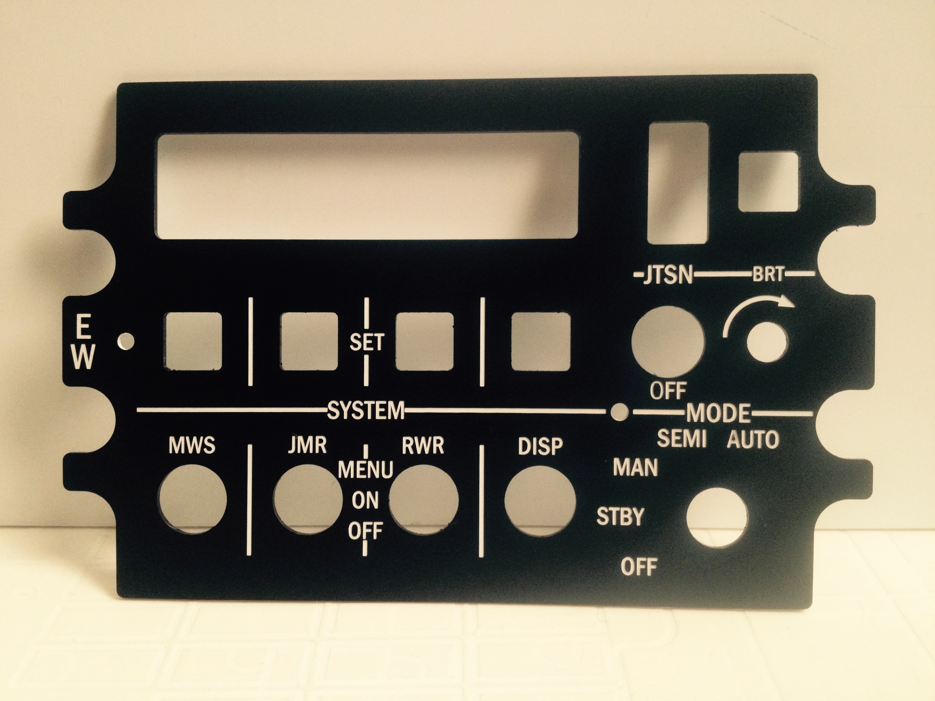
Finally figured out what the problem was! In the G-code options list there is " Velocity Mode". I guess I did not set this correctly during the setup. It was "undefined". I changed it to "Exact Stop" and all my problems went away! Managed to get my CMSP panel finished (almost). I posted it on Lars panel thread since I used his drawings. Clay
-
Lars What do you think? I draw up the buttons myself but the actual panel is from your files. VFD display doesn't show well in pictures! Thanks Clay
-
Lars Thanks for quick change! Now my work begins.... DM Thanks for the clarification! I searched your thread and found your switch info. Thanks for that as well. I have spent many,many hours on this forum and I'm amazed by how much valuable info is buried inside some big threads! Clay
-
Lars Couple of things with "EW" panel Third system switch should be RWR? Probably just a typo right Are you fairly sure the JTSN switch has an OFF label? I dont know myself but I have seen some examples without it. I think it is a momentary switch. Having the "off" label kind of doesn't make sense IMHO. Just asking thats all. Thanks Clay
-
Lars, Heres a pic. Sorry. I need a new camera. Clay
-
Lars I have already cut some your panels. I think the results are great! Thanks again! I was quietly waiting for your CMSP. I already have my old CMSP in pieces waiting for a new home! Looks like my old panels did not have correct height so I want to start at the top of the consoles and work my way down to get the spacing correct. Thanks Clay
-
Lars! Many thanks for your efforts! Clay
-
I can confirm flaps gauge does work for A-10 with DCSBios. Mine is a little jittery but works! Can anyone post their arduino sketch that doesnt work? Clay
-
Lars DXF files would really help me out! Thanks Clay
-
Warhog I am still messing around with fonts. Slowly making some progress! I was checking ( again ) your photobucket page. Would mind sharing which fonts you used for CDU ? I have played around with feeds and speeds and have been getting good results. now its just about the drawing details. Thanks Clay
-
Lars I should have mentioned in my earlier post. I'm still working on getting fonts cut correctly. From what I have been told we should be using stick fonts in our drawings. That way they engrave correctly. If you are also buying a Cnc you should check out my CNC by trial and error thread. Might explains better then I have done here. Thanks again for the .dxf files. Saves a bunch steps for me. Clay
-
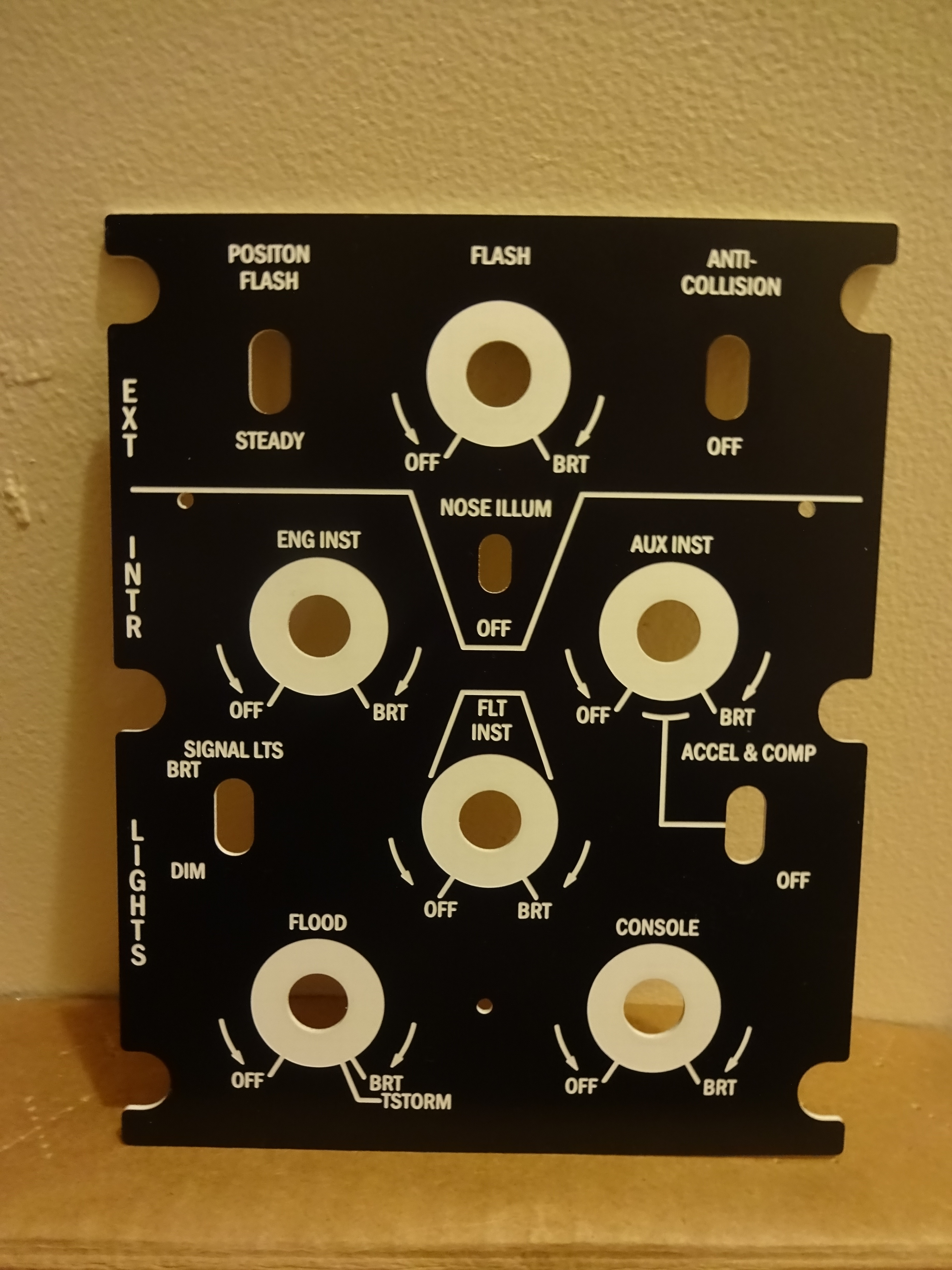
Just noticed something Lars On the ext/intr lights panel. the position switch should be center off. with the "OFF" positioned vertically to the right of the switch. at least i think so??? Thanks Clay
-
Just noticed something Lars On the ext/intr lights panel. the position switch should be center off. with the "OFF" positioned vertically to the right of the switch. at least i think so??? Thanks Clay
-
Thanks Lars! Here's a pic for you. I think we can definitely work with these. It required some conversions in CamBam (Splines to Arcs) but it wasn't to difficult. I'm new to the entire cad/cam/cnc thing. I've only had my made in china 3040 for a few weeks. But I easily managed to get this through cam and into Mach3. The cut time on this panel for me was 1 hour 28 minutes and 15120 lines of G-code! Thanks again Lars Clay
-
I'm want to try and post a video of this somehow. I guess youtube then attach link here? I have never tried the YouTube thing but i will give it a try. Imperial measurements are what I typically use. Its kinda funny that in Canada we have the metric system. But our houses are still built out of 2 by 4's! So I used .0005" as opposed to the .01 mm that metalnwood suggested which is .00039" due to the fact I only have an Imperial dial indicator. I am confident in saying this machine has zero backlash on all three axis. The same results I got after repairing all the loose bearing fits and giving the bearings a bit of preload. By the way this is a ball screw machine. One of the reasons why I bought this model. And before you say "this guy has no idea what backlash is" I deal with it 8 hours a day. Lots of old acme thread (typically 1/4" pitch) leadscrews with worn out bronze nuts that require an extra 1/2 turn or 2 to position properly. If i move .0005" in mach in either direction i get .0005" movement. Mach DRO always matches dial indicator( Mitutoyo 2416S shes a beauty! ). I thinking this might be a controller issue. According to CNCzone swapping out the controller is the first step to getting rid of most of the problems. I also had a closer look at the RomanS font in Adobe Inventor. It seems like the actual font has errors. If I zoom way into the sketches you can see that some of the lines are short. Strange. Clay
-
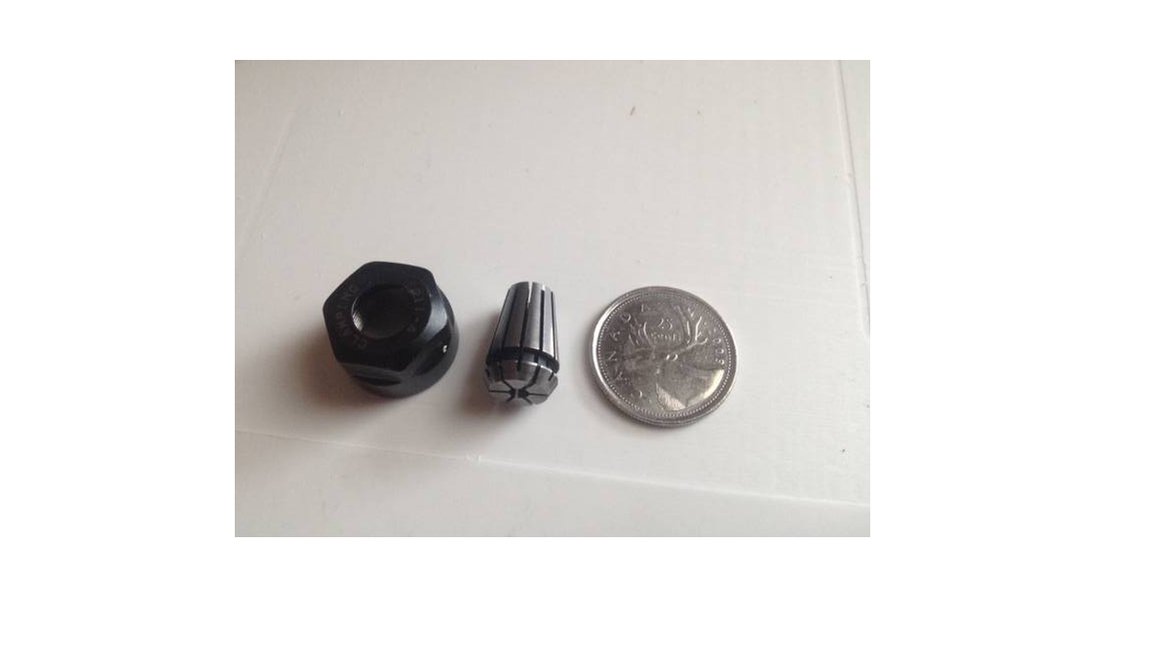
Metal ER11 Not much bigger than a Dremel! About do to do backlash testing but... ADVICE TO NEW CNC USERS!! At some point and time you WILL need to put a dial indicator on your machine. It's not if but when. Many machines purchased today are ALUMINUM. So will need to clamp something to your work surface so that your magnetic base can stick to something, probably with your t-slots if have them. So DO NOT cover entire work surface with your sacrificial board! Leave a corner or something open to mount indicator. Also, if you do cover entire surface and you decide to use fairly thin plastic of some kind ( at least a 1/2" piece of MDF you can screw something onto it ) DO NOT spend half a day leveling it all off so its perfect because your just going to have to tear it off the next day to get to your t-slots! I'll let you guys know how the backlash test goes. Thanks for the tips.
-
I need to get another collet! all I have is the 1/8" AND I only bought 1/16" endmills! So I'm leveling 10" by 11" with 1/16 endmill. Pretty sad. I will get out the dial indicator again tonight. I have a little over 1" stroke dial indicator. When i did this befor I put indicator inline with whichever axis I'm checking. I move using mach3 towards the indicator. Then i position indicator so it reads exactly 1.000. then i zero that axis in mach3 . then move away from the indicator in mach and compare the DRO to dial indicator. Or should I just push and pull everything by hand??? Thanks Clay