sharkfin61
-
Posts
428 -
Joined
-
Last visited
5 Followers


Recent Profile Visitors
8553 profile views
-
How sharp are your labels on the panels?
-

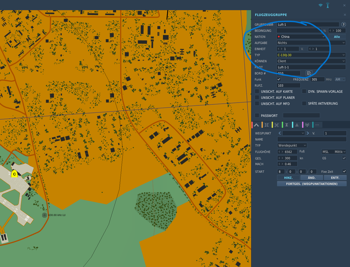
C-130J is not available if you choose germany in the ME
sharkfin61 replied to Butcher59's topic in Bugs and Problems
Ok, thank you. But now it really get's strange with the mission editor: Caucascus theater.
-
C-130J is not available if you choose germany in the ME
sharkfin61 replied to Butcher59's topic in Bugs and Problems
Just tried to change the role to "Tanker", so you can choose the KC-130 for Germany. That, initially, worked out fine. But when you start the flight from the mission editor and choose your slot, you remain 715 feet above Wittstock with no aircraft, just observing the beauty of nature... Edit: Just tried in the Kola scenario, the Aussie C-130 worked (although I could not confirm, the right skin was provided as I'm too dumb to get into the loadmaster view for a walk around, but at least I had a cockpit for now). May our guys from Evreux will show up in a later patch version. -
C-130J is not available if you choose germany in the ME
sharkfin61 replied to Butcher59's topic in Bugs and Problems
Maybe because there wasn't an existing J model during the timeframe of that scenario (cold war), and Germany didn't have any E-H models? Just a wild guess. -
Thank you for your answer, @Vinc_Vega Maybe I'll give it a try for a display, then. I think RS485 isn't a matter for me anymore, I switched my planning and bought some more Leo Bodnar BBI32/64s and BU0836Xs for the most knobs and switches, potentiometers and rotary encoders. Mainly for the flexibility, to program them for other aircrafts, I fly. So, only a few displays and lights are left for Arduino --> USB connections. ATM I'm about to connect all panel lights to my PCU 12V rail, if time permits, I'll see a silver lining at my simmer horizon at the end of the year. Not being able to fly for over 2 years now really sucks.
-
As is contains a 32-bit microprocessor with 48 MHz speed and more memory now, I could imagine, it might bring some relief to slow display screens and such. Any experiences? And most of all, will DCS-BIOS still work with it? UNO R4
-
Looking for a Warthog stick extension..
sharkfin61 replied to sharkfin61's topic in 3D Printing for DCS
Received it yesterday, test-installed fitted lika a glove. Now next will be the AVA. 1a quality for now, as I cannot test it in flight. Very pleasant wiring and materials. Regarding the price tag, the 52 GBP ebay item ended as a ~100€ buy, due to taxes and shipping (just as an info for other buyers). Again, thank you @Nightdare and @_Hoss for pointing me to it. -
Looking for a Warthog stick extension..
sharkfin61 replied to sharkfin61's topic in 3D Printing for DCS
Thanks to both of you Nightdare and _Hoss. @Nightdare, if I had it manufactured as a single product by my needs, I'm sure, I would cost me a fortune over here in ole' Europe (expec. with the "wonderful" tarrifs nowadays ). But a very interesting website, indeed. @_HossUnfortunately the Thrustmaster extensions are not really what I am looking for. I already fly with a straight 4" extension from Sahaii, but I had to bring the Warthog base to level with a plastic tube. On the other hand, the long extensioon seems to be rather for choppers. Your's _Hoss looks very close to what I'm looking for (200mm curved). Will take my stroll on ebay now. -
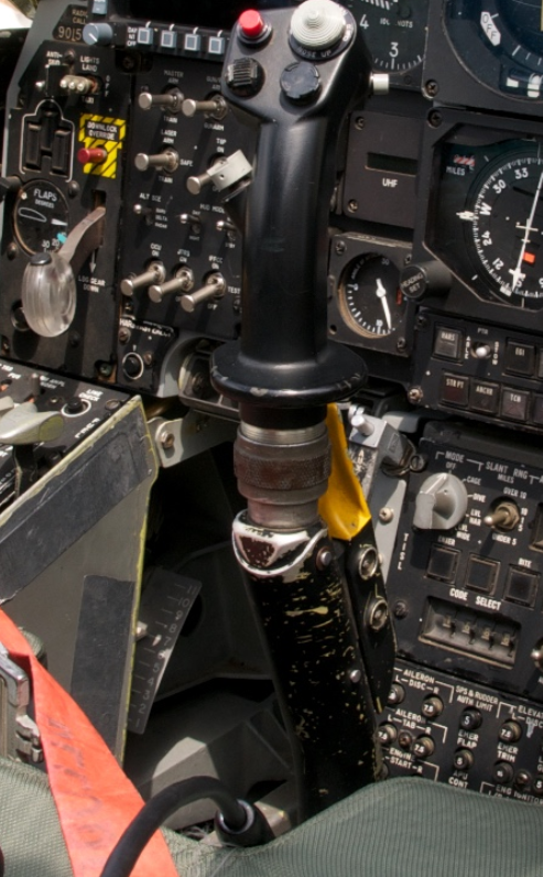
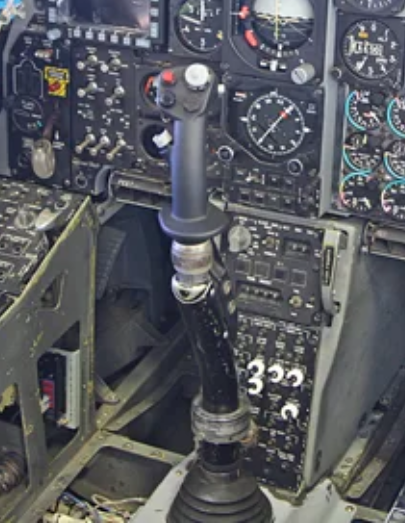
Did anyone stumble upon a Warthog stick extension, resembling the "real" shape of the A-10C's controls, to fit on the TM AVA base? Doesn't matter if 3D printed or made from metal. Thank you. (picture kindly taken from: https://de.m.wikipedia.org/wiki/Datei:Fairchild_Republic_A-10A_Thunderbolt_II_cockpit_2_USAF.jpg)null and: https://www.instructables.com/Start-off-with-a-fresh-Poster-Boards/ null
-
Has anyone found some brass inserts for 3D printed knobs?
sharkfin61 replied to sharkfin61's topic in 3D Printing for DCS
Update: I received the last 29 inserts after almost half a year, so, I can only recommend that seller if youre not really in a hurry (well I wasn't completelety his fault, but after he finally received a working batch of the inserts with the holes drilles and threaded, he simply forgot to sen them to me) -
@JohnnyChicago Have you already completed your RS485 installation? (I'm still hesitating...) May I ask you, how powerful your PSU is?
-
Zwar nicht die exakt Antwort auf Deine Frage (Komprimierung), aber was würdest Du von einem Auslagern der Terrain-Daten auf eine zweite Festplatte (Verknüpfung mit DCS per "hardlink") halten? Dann könntest Du die Installation auf der 870er EVO lasssen, nur die Theater auslagern. Hier wird's beschrieben, bei mir funktionierts gut.
-
Just as a reminder or hint for the ones whose 3d-printers slicers can't cope with .sdlprt files from Solidworks (like my orca or bambulab slicers): Instead of trying to get a demo/ degraded license for the main program, go for the e-drawings pro, a 3d viewer from Solidworks, with which you can save the .sldprt files in a .stl format. number 4 in the list Or, even better for the ones, who are willing to learn Solidworks from scratch, buy a makers license for 24 USD/ year : https://www.solidworks.com/solution/solidworks-makers
-
- 3
-

-
@No1sonuk Ahh, very pleased to hear that.
-
@Gareth Barry just yesterday I looked up solutions for a similarr problem, however, I'm not as far as you are. I was trying to develop a wireing plan for my pit. Now, to get to the point, regarding the 5V supply of the Aduinos (you need in fact 7V per unit), I read, when you connectz the powerjack, you cant have the USB connected, Thus making your forwarding if inputs to the PC quiet difficult. If anyone knows better and can tell me the opposite, please do. What I have done so far to supply my hardware are powered usb3 hubs (RSH hub ). But as I said, I haven't the expirience with a fair amount of arduinos, only with 2 so far. They were working together with TM HOTAS, pedals, UFC, TIR, headset, 2 TM MFD's a ,CDU, a wireless mouse, all on USB ports.