lesthegrngo
-
Posts
1245 -
Joined
-
Last visited
Content Type
Profiles
Forums
Events
Everything posted by lesthegrngo
-
Hi All, I'm looking for some advice on how to clean up what appears to be multiple installations on my PC I updated to the latest stable version of DCS, but when I clicked on the icon on the desktop it opened, reporting that it was at version 2.5.6.49798, also showing me logged in and with the A10C pack installed (from a DVD bought years ago) However it was supposed to be 2.8.4.39731. When I started looking around I saw a new DCS icon on the desktop as well as the one I normally use, this one titled 'DCS World'. When I clicked on that, it opened and correctly reported the version as being 2.8.4.39731, it also showed me that I was logged in.... but that the A10C pack was not installed. When I right click on the properties one each Icon, this is what shows up - this is the 'old' version DCS World "D:\DCS World\DCS World\bin\DCS_updater.exe" "D:\DCS World\DCS World" and the new DCS.exe - Shortcut "D:\DCS World\bin\DCS.exe" "D:\DCS World\bin" So somehow I have managed to create two instances of DCS inside the DCS World folder I prefer the non-steam version of DCS as I run the DSC BIOS system to interface my home built cockpit. So what I want to know is how to clean this up and get the already registered DCS A10C pack to show up on the updated version. Both versions are logged in with the same ID, and neither seems to conflict with each other. I am happy to keep the older version in case there is an issue with the new one but need the A10C DLC to show up and for there not to be any conflict Any help given is gratefully received Les
-
Thanks I saw an arduino controlled dimmer while looking at the various circuits. It's tempting, but at least at the moment I'll keep it simple. One other question, the way this would dim is by a square wave, right, rather than a sinusoidal wave. That means that the LED's will strobe, I just want to check whether it would be intrusive, as I know peripheral vision is more sensitive to it Les
-
Hi All I have a number of panels that are LED backlit, mostly 12v DC powered. The problem is that they are quite variable in their brightness, and so I would like to have a simple module for each one that allows me to regulate them individually to match. I was thinking maybe a small PCB with something like a PWM controller and a trim pot, and found this https://www.circuits-diy.com/led-dimmer-circuit-with-555-timer/ It looks simple enough, except that the 'picture' doesn't show the extra diodes and capacitors. The questions I therefore have are: are the extra components there to compensate for the fact that the input voltage on the schematic is shown as 5 - 18v? Bear in mind my input will be a stable 12v I will be using it with up to 50 surface mount 0805 LEDs ranged in banks of four, would the MOSFET still be required? I was hoping some kind of surface mount device could be used instead for packaging reasons Is there any reason why the potentiometer can't be replaced by a small SMD trimmer pot? Ditto the resistors and diodes, assuming I can get suitable ones Cheers Les
-
Thanks - I have the Adafruit font I need to modify, and it's not a lot of modification needed - if there is something that can import that so I can save it as a renamed file with the correct header constructor that would be great Les
-
Hi all, I am trying unsuccessfully to use this font editor https://tchapi.github.io/Adafruit-GFX-Font-Customiser/ to modify a font to suit my needs, but it just doesn't work - it won't export the file, you just end up copying the modified code without the correct headers, making the output useless Can anyone point me to a good .h font editor? Cheers Les
-
Yep, that was it.... so simple, but I didn't spot it! Cheers Les
-
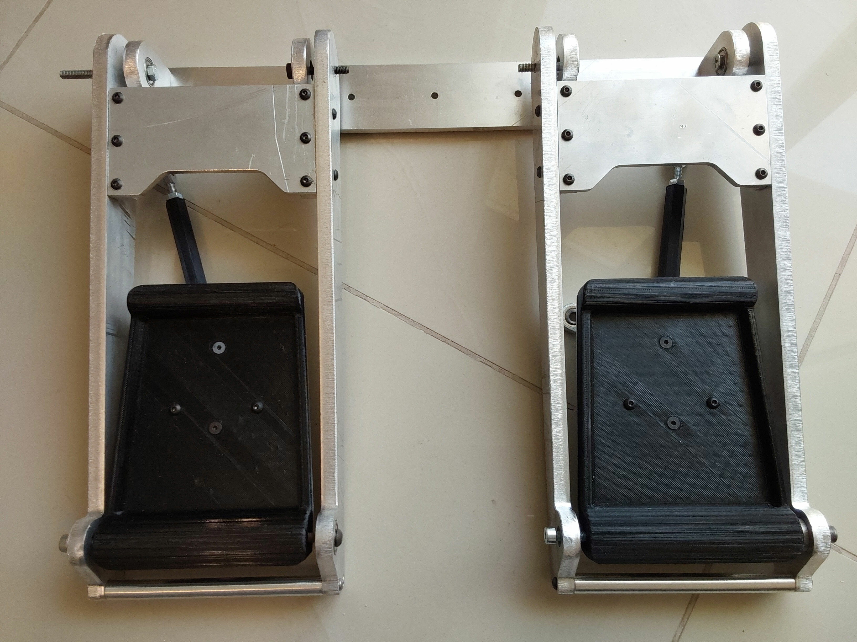
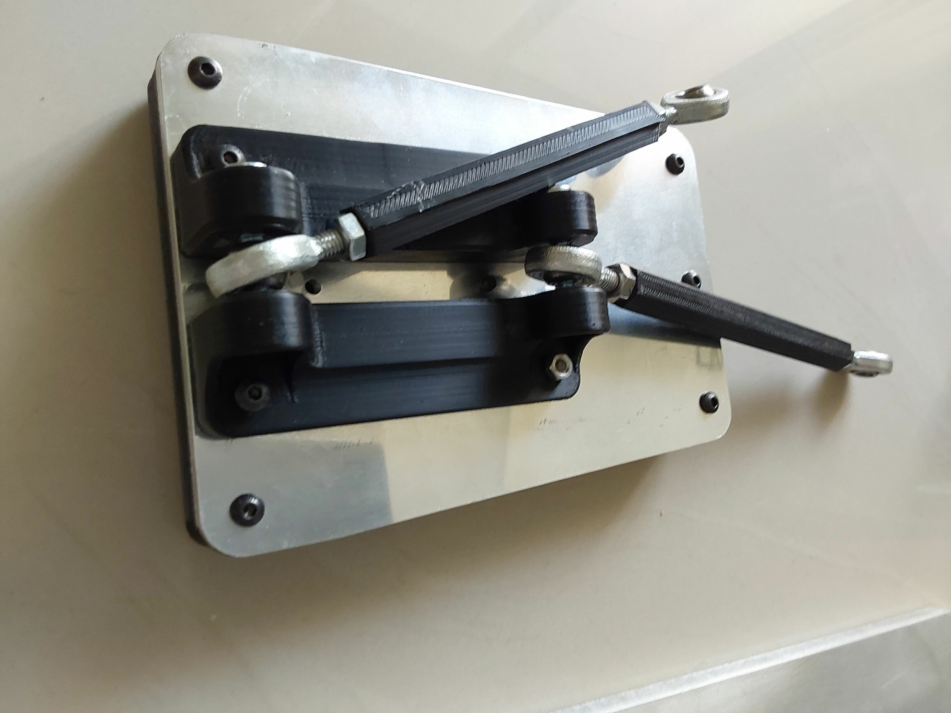
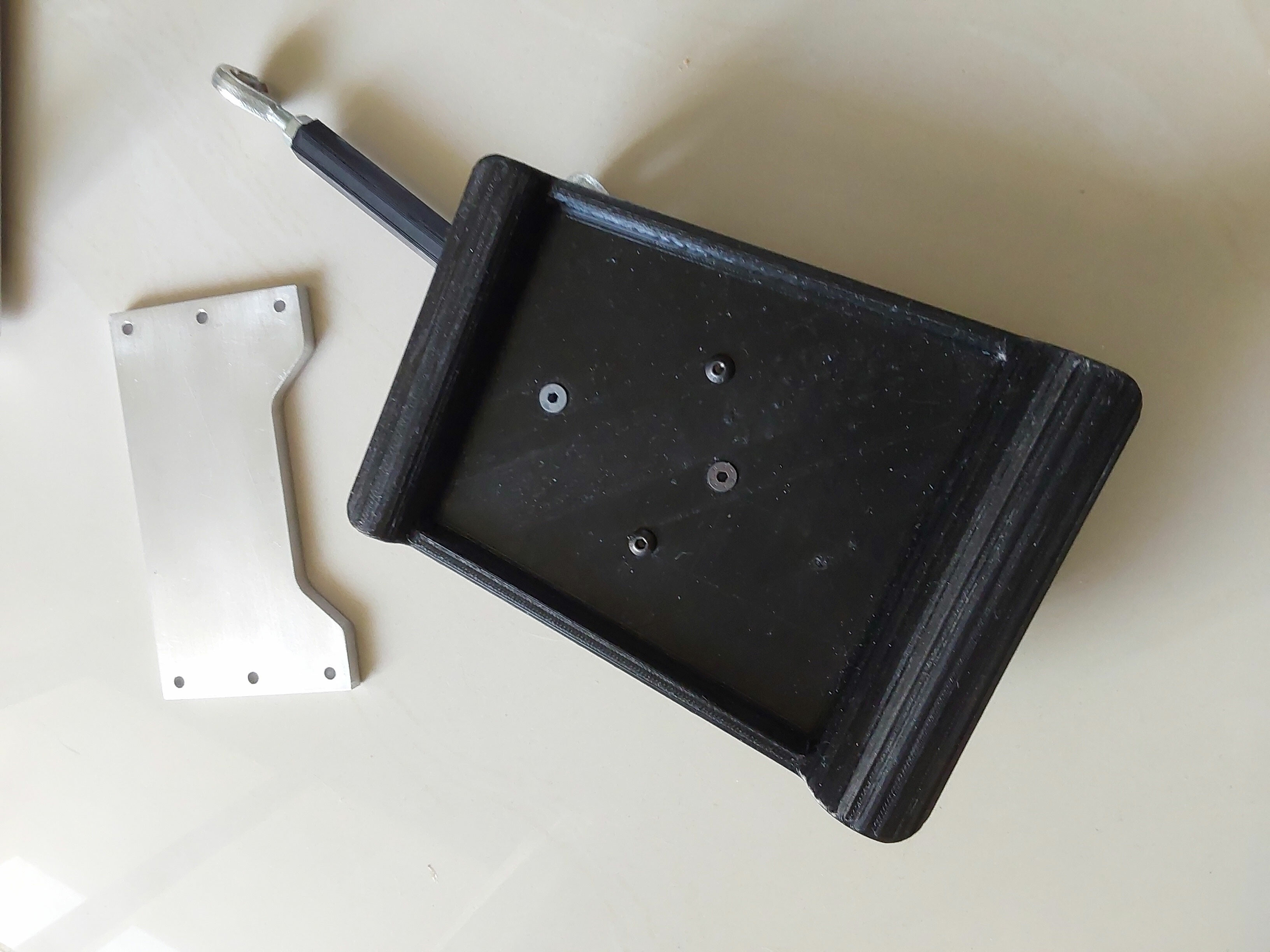
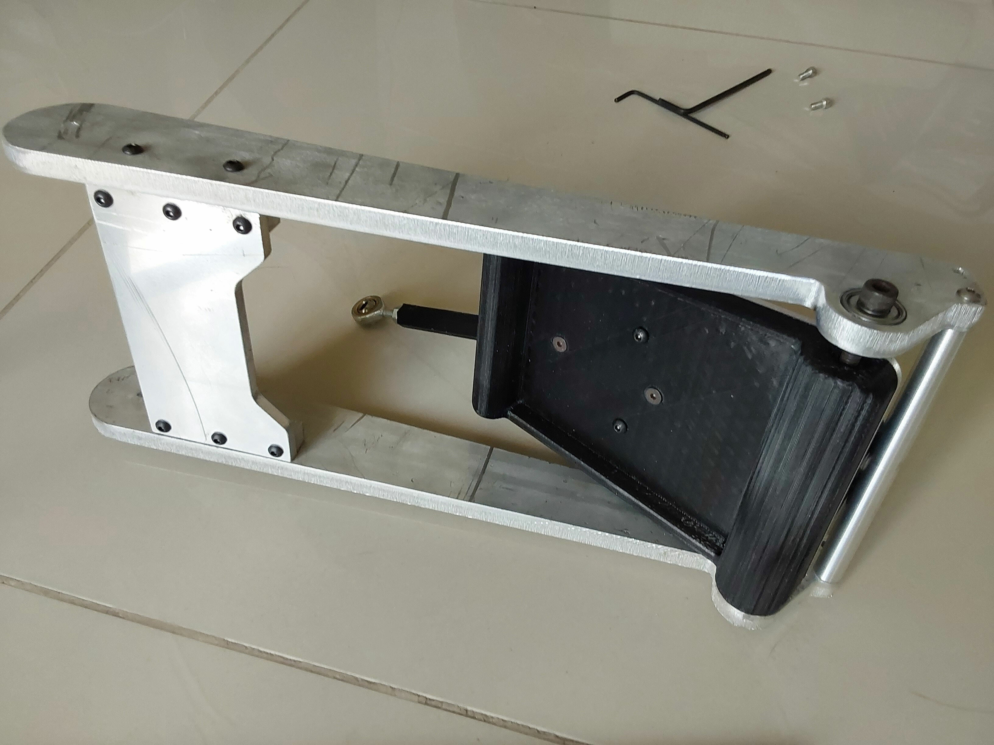
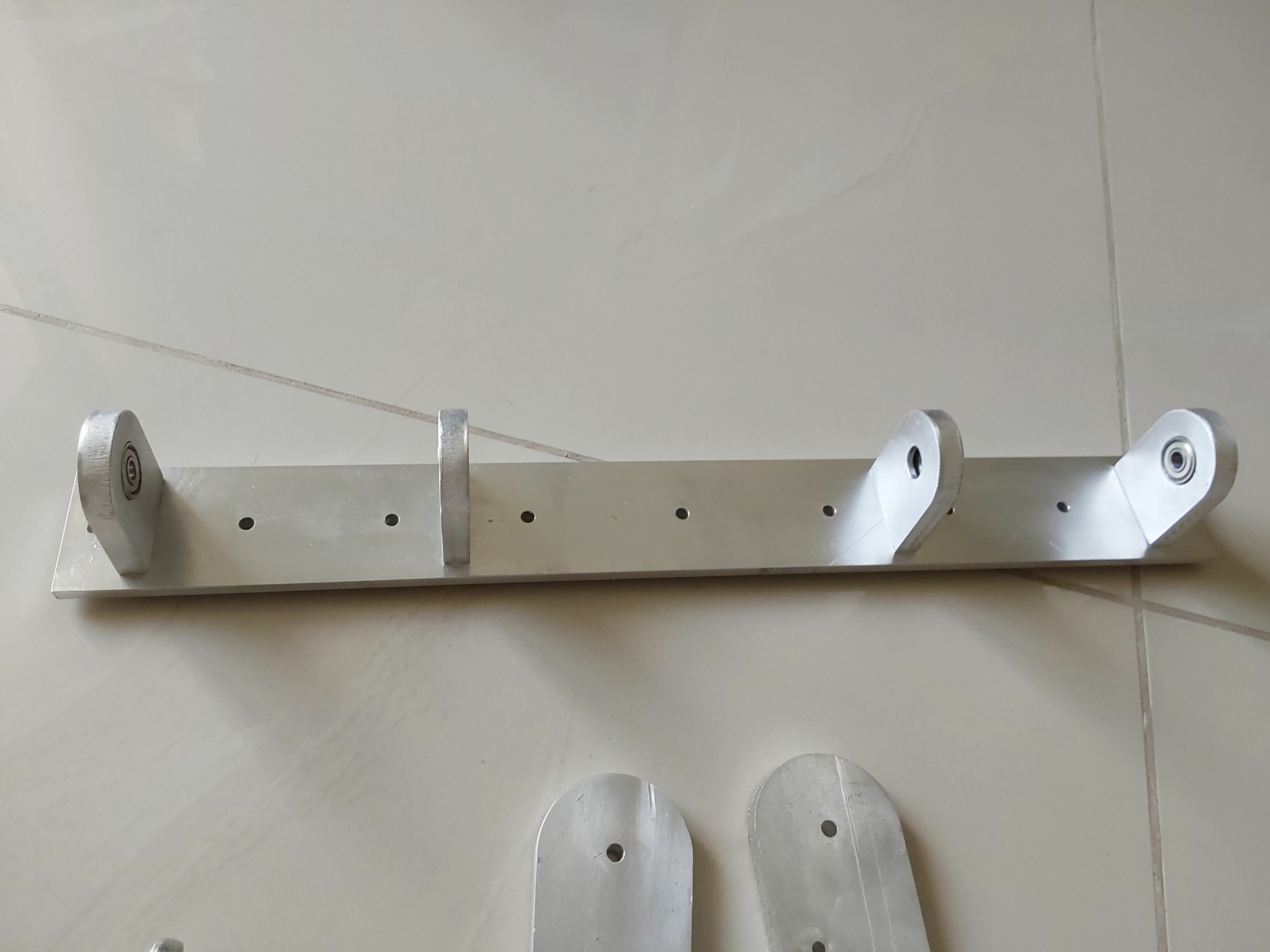
Some more pictures of the pedal sub-assembly Cheers Les

-
Hi Vinc, yes, and that was with the first wiring setup - it worked fine for the both the hardware and software modes, including with the rearranged pins. There's obviously something injected by the DCS Bios part that it doesn't like Cheers Les
-
the pin selection was just for ease of test connections, using a straight JST header, so I can certainly redo the pins in line with that Just tried it, still generates the same error Cheers Les
-
Hi all, I am trying to update my ILS panel with a 2.23 SSD1305 128X32 OLED panel. I have the following simple sketch but it is generating the errors below #define DCSBIOS_IRQ_SERIAL #include <DcsBios.h> #include <Wire.h> #include <SPI.h> #include <Adafruit_GFX.h> #include <Adafruit_SSD1305.h> // Used for software SPI #define OLED_CLK 8 #define OLED_MOSI 9 // Used for software or hardware SPI #define OLED_CS 12 #define OLED_DC 11 // Used for I2C or SPI #define OLED_RESET 10 // software SPI //Adafruit_SSD1305 display(128, 32, OLED_MOSI, OLED_CLK, OLED_DC, OLED_RESET, OLED_CS); // hardware SPI - use 7Mhz (7000000UL) or lower because the screen is rated for 4MHz, or it will remain blank! Adafruit_SSD1305 display(128, 32, &SPI, OLED_DC, OLED_RESET, OLED_CS, 6000000UL); // I2C //Adafruit_SSD1305 display(128, 64, &Wire, OLED_RESET); void setup() { Serial.begin(9600); DcsBios::setup(); } void onIlsMhzChange(char* newValue) { display.setCursor(0, 0); display.print(newValue); } DcsBios::StringBuffer<3> ilsMhzStrBuffer(0x116e, onIlsMhzChange); void onIlsKhzChange(char* newValue) { display.setCursor(50, 0); display.print(newValue); } DcsBios::StringBuffer<2> ilsKhzStrBuffer(0x1172, onIlsKhzChange); void loop() { DcsBios::loop(); } These are the errors HardwareSerial0.cpp.o (symbol from plugin): In function `Serial': (.text+0x0): multiple definition of `__vector_18' C:\Users\LES\AppData\Local\Temp\arduino\sketches\A037ED41BCCC8E76B075F474E42FD7AF\sketch\ssd1305testILS_copy_20230603100723.ino.cpp.o (symbol from plugin):(.text+0x0): first defined here collect2.exe: error: ld returned 1 exit status Multiple libraries were found for "Adafruit_GFX.h" Used: F:\Users\LES\Documents\Arduino\libraries\Adafruit_GFX_Library Not used: F:\Users\LES\Documents\Arduino\libraries\arduino_196778 exit status 1 Compilation error: exit status 1 I tried it with the hardware SPI constructor and it gives the same error message Can anyone advise on this? I have restarted the PC in order to flush any temporary files, although not sure that guarantees it. This should be a simple one, but it is the first time I have used the SSD1305 library Cheers Les
-
It needs to be rotated through 90 degrees, so in the cases on ones that are not square unfortunately that doesn't work due to shape being wrong. Flipping it front to back will not change the polarisation Cheers les
-
Yes, although it's not quite as simple as just putting polarizer film over the top, you have to remove what is there already otherwise it acts weirdly. Also I had to get a couple of types of polariser before I found one that was suitable, although as long as you avoid ones with mirror film or other treatments you should be OK Les
-
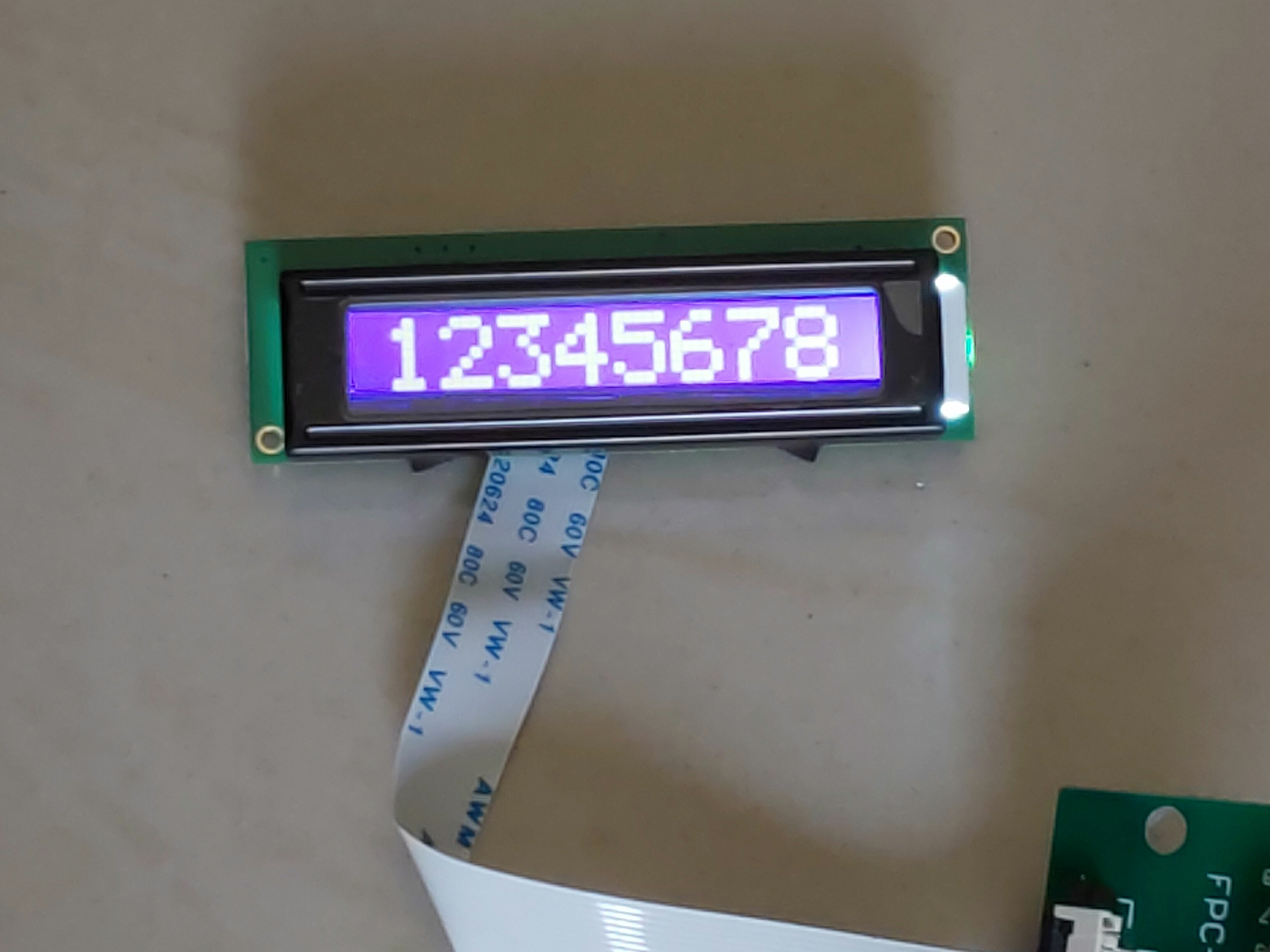
If anyone is interested, I have converted my black on white LCD character displays to white on black(ish), you can see a before and after. I searched fruitlessly online for these 8x1 modules in white on black, and was always unhappy with the CMSC having the black on white displays. While not a true black background, it is way better than it was It's not difficult, but it is a bit fiddly. If there is enough interest I will extend this with a how to Cheers Les
-
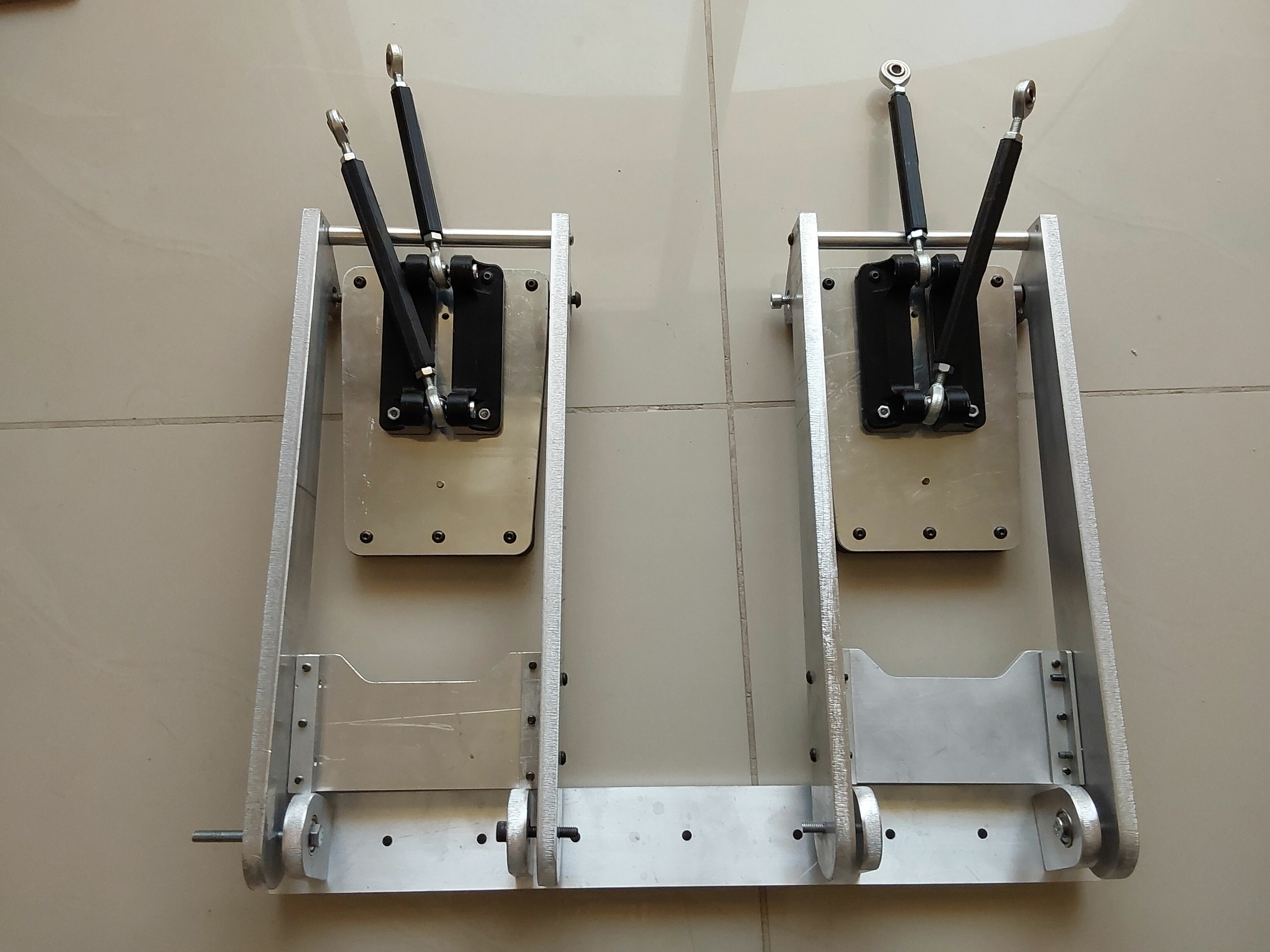
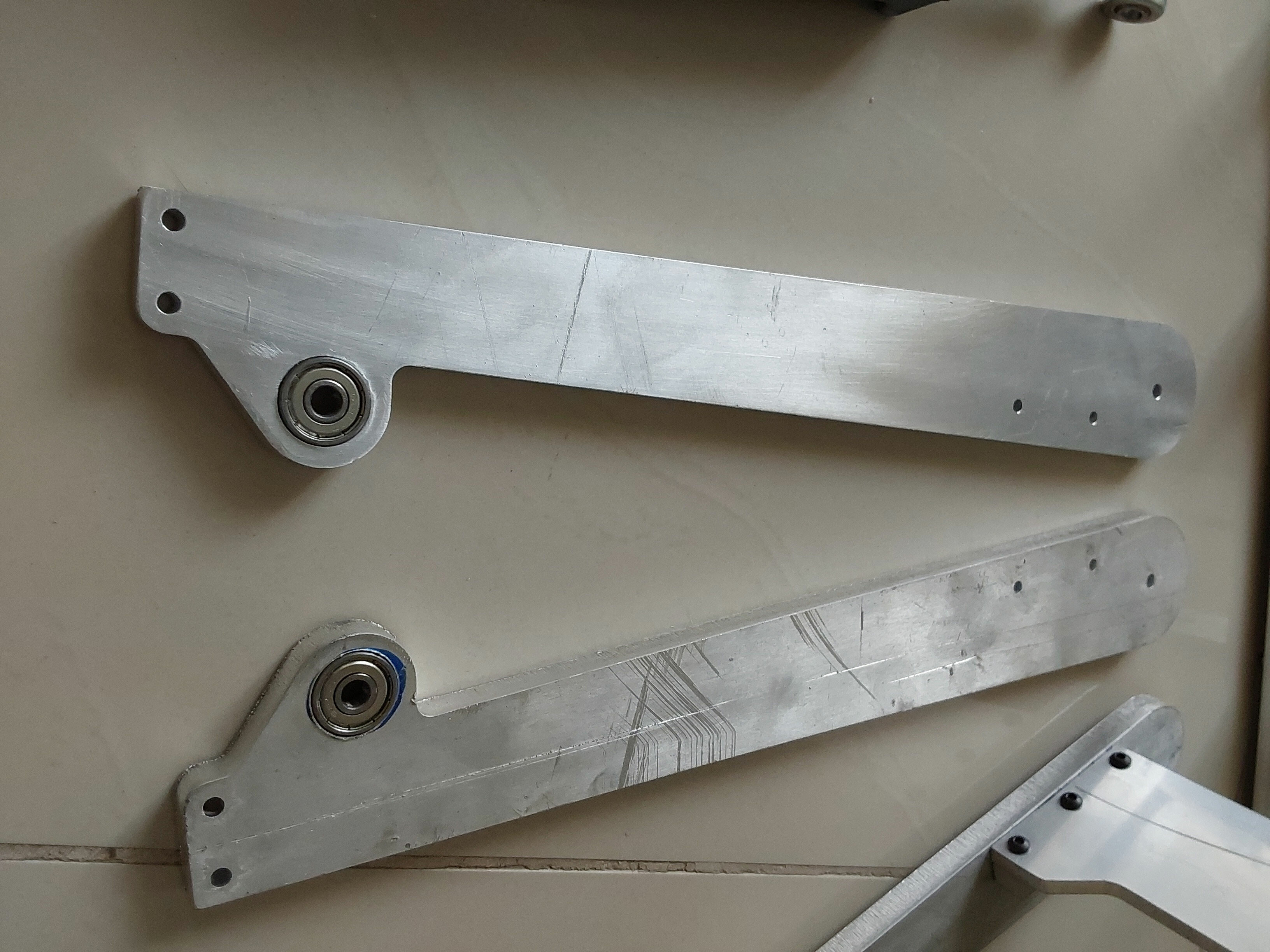
Here are the new pedal parts to convert my Crosswind unit to pendulum type pedals. The parts are a bit over engineered, but are nice and beefy so once tightened up are very rigid and rugged. They use 19mm OD 6mm ID bearings to make sure everything is smooth and free of any unwanted movement. You can see the 3D printed pedal pad with a 4mm aluminum sheet backplate to ensure strength, and to eliminate flex. The parts are predominantly laser cut, with the major parts from 10mm thick sheet pocketed to take the bearings. I will have to have to either turn or 3d print some spacing bushes to ensure the pedal pads sit in the correct location, and also to ensure that the stirrups are located correctly. I can fine tune using the bushes. The crosslink mounting is also mounted with bearings, and should help me with the adjustability I'm a bit disappointed in the rather scratched surfaces of the parts, this is from the shop that laser cut the parts for me - I expected them to be a bit more careful. I have cleaned some up but have a way to go yet but eventually I will have them looking more presentable Cheers Les
-
Check to see if you have two sketches in the sketch folder - I had that without knowing it and it caused errors. Apparently the IDE reads all sketches in the folder as one overarching sketch and this can lead to multiple declarations and conflicts Les
-
Great, happy I could help cheers Les
-
Here is a characters.h file I have for my altimeter sketch (A10), try copying it to the sketch folder and see how you get on characters.h Les
-
Did the original location have the file? The .h file will be the actual characters that the sketch needs to display the gauge, in place of using a standard font. If you can't find it you will have to recreate the character.h file by using a bitmap to make the individual characters and then converting them to an .h file What was the original source of the sketch above? Les
-
This looks like you have the wrong bootloader chosen - I get this error when I try loading an ATMega328 using the AT168 loader Cheers Les
-
Using more than one Arduino pin as LED output
lesthegrngo replied to lesthegrngo's topic in Home Cockpits
Thanks guys, so different ways to do it. It won't be many instances, so even the longer version would be OK, so it's nice to know the ways Cheers Les -
If I want to drive two different LEDs as a particular warning light, can I assign an LED output to more than one pin? Cheers Les
-
Searching turns up so much that it becomes more confusing than helpful A separate area is more logical cheers Les
-
Alternative to DIview that reports more than 32 buttons
lesthegrngo replied to lesthegrngo's topic in Home Cockpits
Apologies for not responding sooner, I was travelling I tried this, but it doesn’t seem to play nicely with the Bodnar 64 button boards. Other devices are ok, but plugging in the Bodnar device crashes or locks up the program, and plugging in the board first then starting the program results in the Bodnar board not appearing on the drop down list. thanks for the help though! cheers Les -
Hi all DIview and the windows USB game controller software are great for checking devices that have up to 32 buttons plus the hat / POV switches. Unfortunately once you have a controller that has more than than, the extra buttons will not be reported. Normally that's not an issue as the in-game controller set up recognises them, however I need to test some units with the Bodnar BBI-64 boards, and have to do so on the bench, not installed. Bodnar doesn't seem to have any suitable programs for download on their site, so I want to know if there are any suitable programs out there Cheers Les
-
Incredible, isn’t it? You’d think it would be so simple, but trying to unlearn the QWERTY layout is nigh on impossible Les