jayyang
-
Posts
31 -
Joined
-
Last visited
-
go check with DCS-BIOS, it's Arduino-based.
-
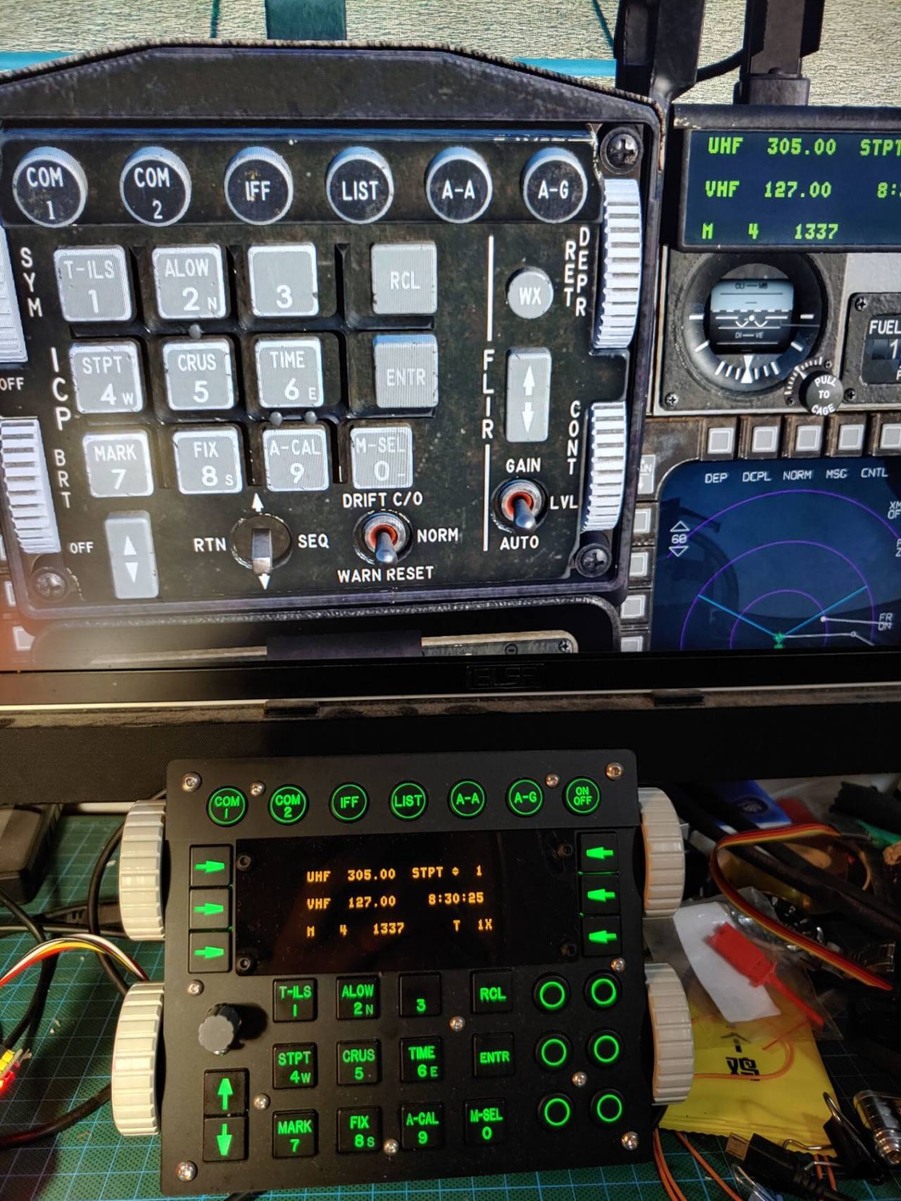
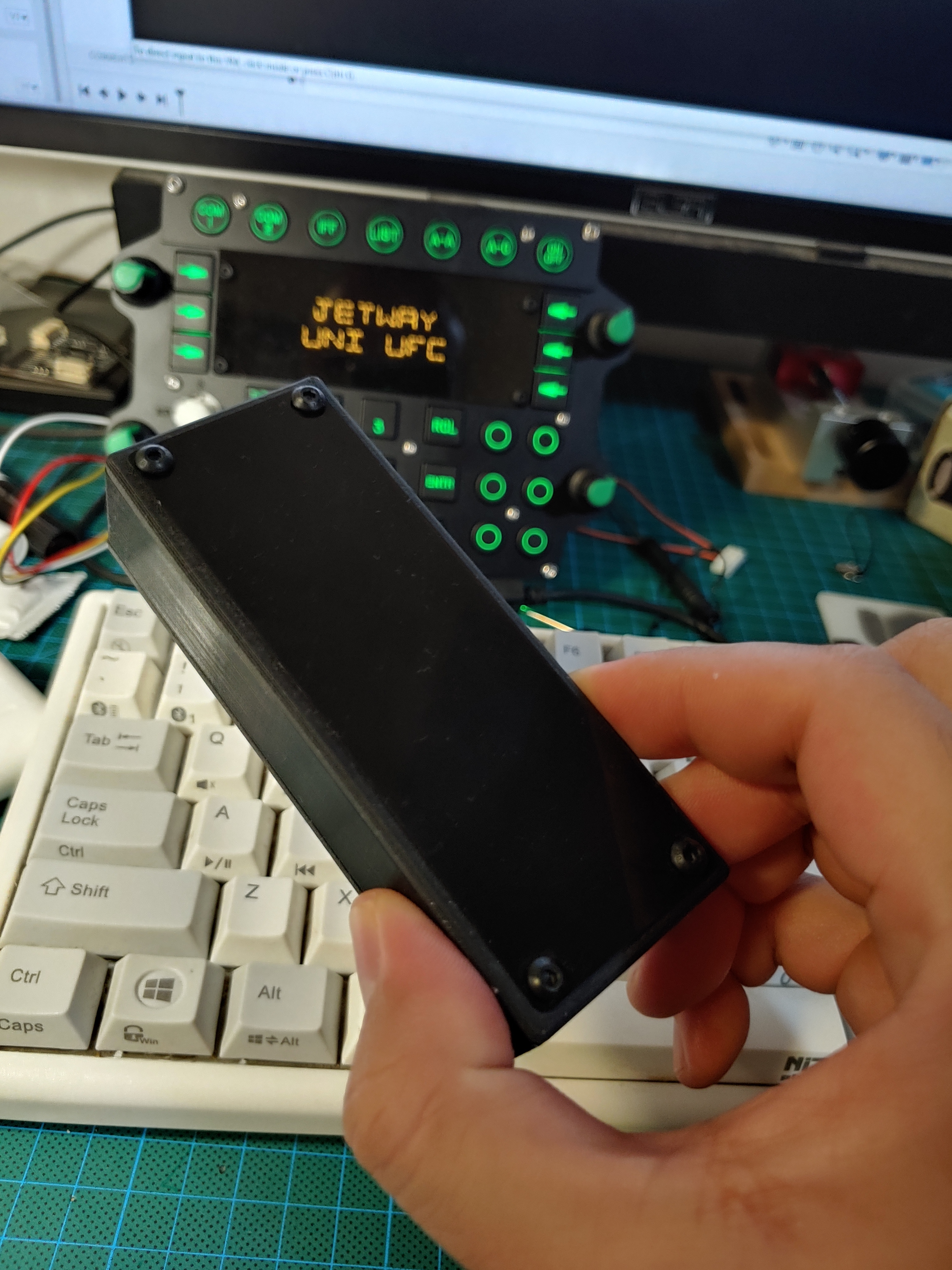
Layout inspired by the F16 Block 60(or 70?) from UAE/Turkey Version. Display is 25664 OLED and common 6x6 LED tactile, panels are laser cut matt acrylic. Buttons/wheels are SLA 3D prints, painted and CNC engraved. At least it can cover F16, FA18, AV8B. and maybe more modules if i have time to code for the OLED display. Also a dedicated DED as a side product, can used for display different data/graph. Likely make it for IFEI(text only) or F14 engine gauges(Graph)? babysitter husband means very slow WIP.....

-
DIY MFD - should I have used shift register - how would it look like?
jayyang replied to Jyge's topic in Home Cockpits
Shift reg is the best, precise, no shadow, simultaneous press, easy coding, easy expanding by chain... Beside VCC/GND, only 3 wires for CLK/DAT/CS, and they can be shared in some design, save a lot of MCU pins. For PCB drawing, you can try KiCad, it's free and not bad. -
Just found the input command and definition are not match. As sample, the RPM control for pilot. It'd defined as Button_15 in "Clickabledata.lua". But assigned with Button_19 in Input Default.lua. Hence, the actual key binding to keyboard/joystick will not work correctly. After change from Button_19 to Button_15, it works as it should be.
-
Any of 60 hawk variant i will accept!! make it and take my money !!!
-
Thanks for your prompt respond for this!
-
Can this tool extract MFCD screens without setting up viewports in monitor config files?
-
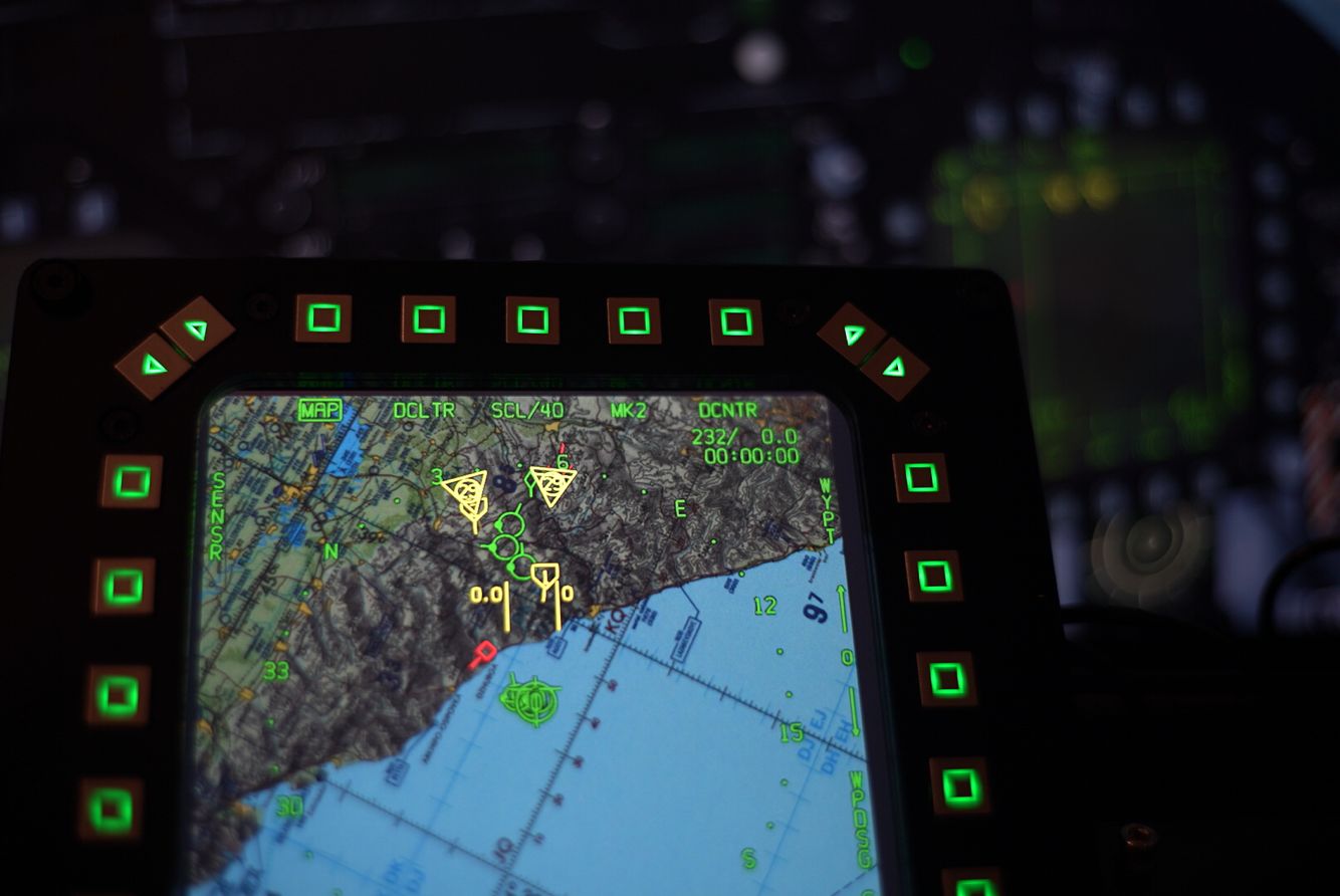
Since it's not easy to find any 5by5 display, no matter CRT or LCD, just fit it with the display device you have...... For my case, i fit it with a 8 inch 4:3 display panel.
-
Seeking help for how to change the output value from original object triggervalue. For example. a 3 way toggle in HELIOS return 0/0.5/1. C54,3001,1.0 C54,3001,0.5 C54,3001,0.0 But F/A-18C Dispenser Switch position is 0/0.1/0.2 like below C54,3001,0 C54,3001,0.1 C54,3001,0.2 How to modify it from Helios Profile? Thanks.
-
Multiple LCD displays using one Arduino Nano
jayyang replied to lesthegrngo's topic in Home Cockpits
I2C can use Address to differential the units, you may check the datasheet of PCF8574 or maybe the silk of the PCB of your LCD. OLED usually comes with I2C or SPI, I2C using address as well, and most of time there are pads on the Circuit board to let you choose. SPI will be much simple, each device has it's own CS(SS) pin, and share the rest of CLK/MISO/MOSI pins. -
Some other pictures showing those buttons are not 100% aligned. Especially the lower part of MFD. https://defence.pk/pdf/threads/jf-17-thunder-cockpit-and-analog-machine-photos.81603/
-
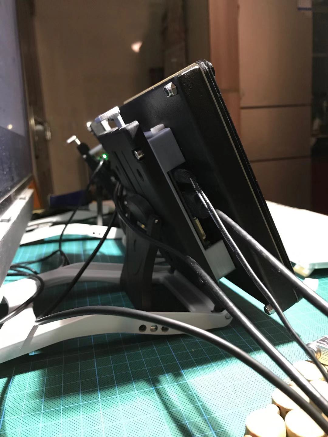
Yes, i made my own PCB to minimize the thickness.
-
https://www.aliexpress.com/wholesale?SearchText=tactile+switch+with+LED try from here, just find one you feels good and ask them to provide the CAP together. CAP can be with different symbol. Like an Arrorw or power, just the usual things you may seen somewhere in your daily life. https://www.aliexpress.com/item/32916434114.html
-
There is no way to get a 5 inch 1:1 square panels with acceptable price. I found a factory in China can made that, but the floor volume is 500pcs... and still sky high. I m actually running a 8 inch 4:3 IPS panel and do the cover job. the buttons just usual tactile switches with LED which is very easy to get in China(with Aliexpress).
-
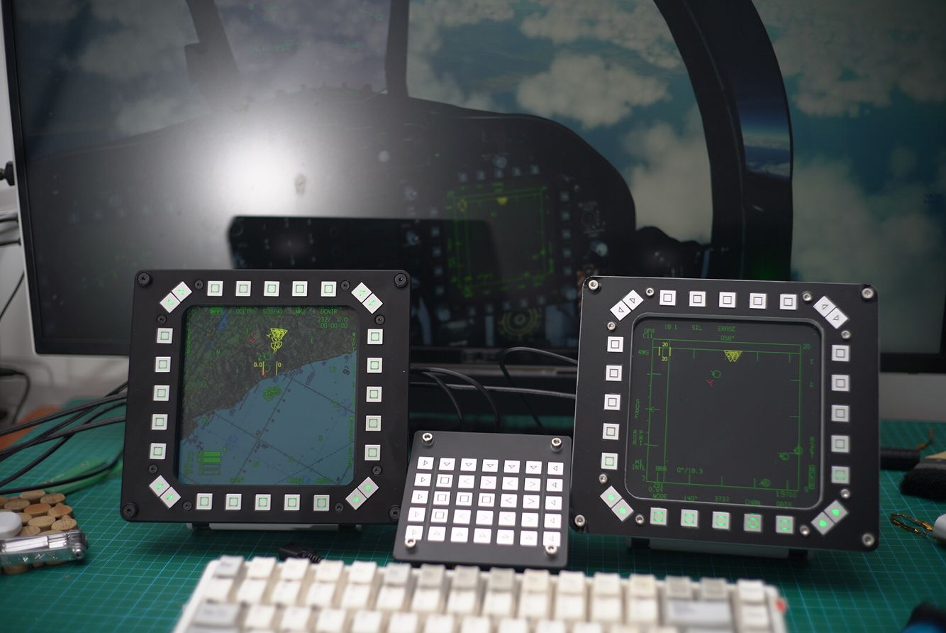
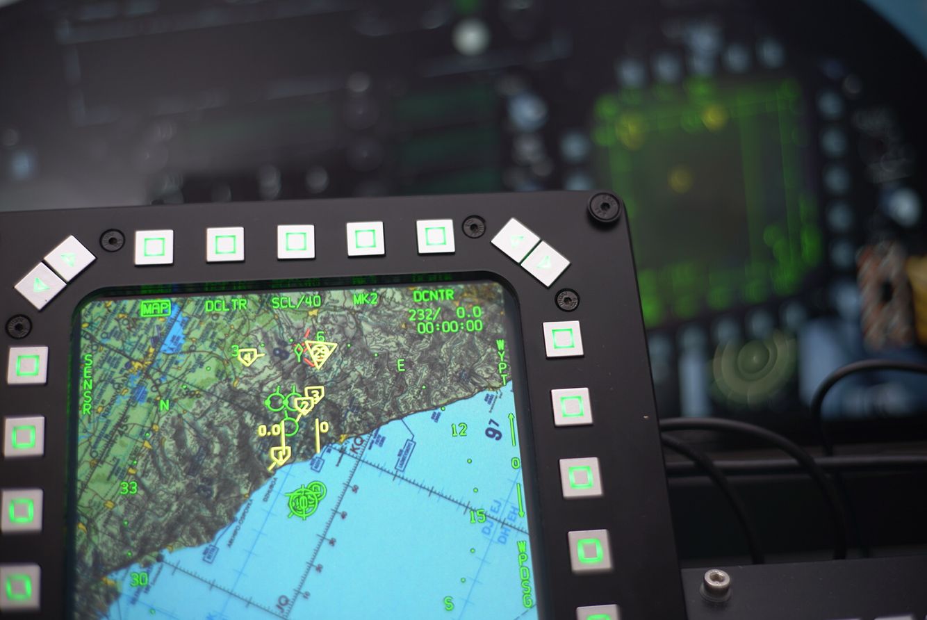
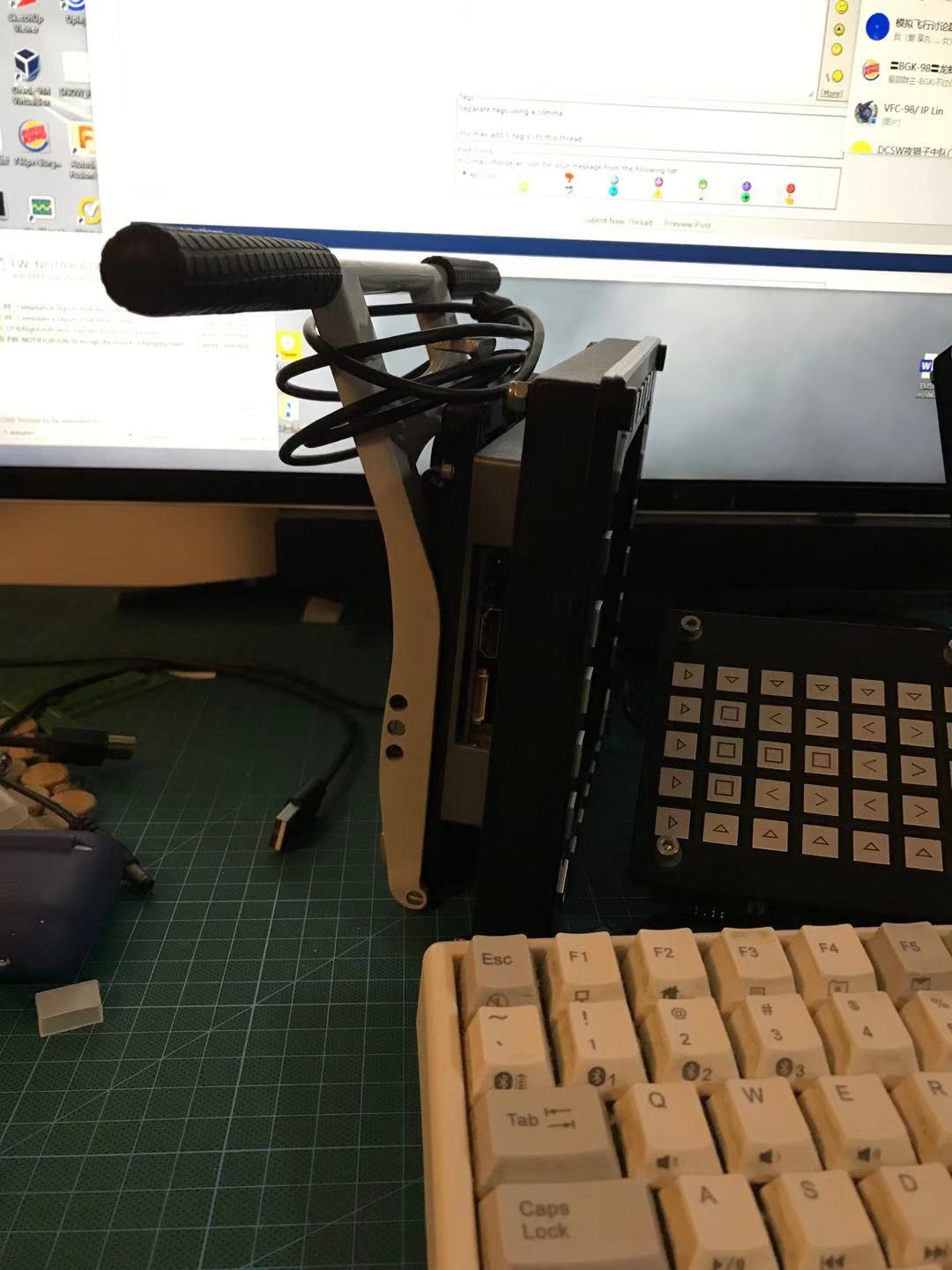
This is a custom made MFD/DDI for those square-like MFD planes. For my small room and desktop which cannot suit with a full size cockpit. USB/HDMI connection, angle adjustable, fold-able. Custom made metal chassis. Button back lit can be adjust by a knob. (I m lazy to write another code to communicate with HID...) Yet, it still VESA10 back mount ready, whish i have my private space in future. In the video, left MFD is a nearly FINISHED one, while the right one is last prototype. Some circuit component with incorrect parameters caused the scan effect under rolling shutter of my OSMO. But actually it's not flashing at all.