CorporalCarrot
-
Posts
33 -
Joined
-
Last visited
-

CNC Settings for milling and engraving panels
CorporalCarrot replied to Savvy's topic in Home Cockpits
Two things to consider when using the "Bit Fan" is that it may affect accuracy, and be a potential source of injury if you are not careful. The idea is pretty sound, but the thing to keep in mind is that the fan will be rotating at whatever speed you set the machine spindle too, which is usually as fast as possible for most people (in excess of 8,000 rpm on basic machines, but higher end hobbyist spindles can reach 20,00rpm or more). As the instructions are to manufacture them yourself, most people would print them (I guess, the .nc file might not work with anything other than the bantam machine it is written for). It is likely that the fan won't be very well balanced. At low RPM this probably isn't much of an issue, but at higher RPM it will start to have an effect on accuracy (i.e. a 1mm slot drill may produce a slot that is >1.0mm). This will be more noticeable on lower end spindles (with lower quality bearings) and lower stiffness spindle mounts. Your design/product may not be affected by this effect, as the effect maybe be too small to notice, but if you are milling PCBs with a 20 deg. V-bit and looking for small traces, then it could easily be significant then (although you should not be blowing the debris from a fibre glass copper clad board anyway - the dust is highly irritant if inhaled and will do you no favours! - Vacuuming is the way to go here). The other problem could be that the fan fails at high RPM, sending bits of plastic out like a grenade. They are unlikely to do any serious damage if they hit a clothed part, but if they ping you in the eye, which could cause some serious injury. I'm am not trying to put people off using them (they seem like an innovative solution for many), but just be weary of these pitfalls and account for them accordingly. Personally, I have a small shop compressor, which provides compressed air and I've made a small nozzle to blow regulated air on the cutting tip (although mostly to cool it). If you get into manufacturing bits and bobs, they are worth the investment. You can pick up cheapish ones for around £100 in the UK, but do your research and make sure it has the necessary rated flow rate (otherwise it won't keep up and run out of air and/or kill the compress by over working it). Mine is rated at 14 cfm, but I do a bit of sandblasting and spray painting too (although it is only just up to those jobs). 9 cfm compressors are probably entry level imho. ...having written the above, I've overlooked the more obvious solution, which I use most of the time anyway! Vacuuming the chips is probably the most straightforward way of keep the cutter clear! It also means no mess at the end of the run You could use a domestic vacuum cleaner, but they are not intended to be used for extended periods of time, and can overheat quick easily and burn out. I have a workshop dust extractor, which is designed to run for longer periods of time and work with clearing swarf and other debris. This one is not the exact model I have, but very similar. Just got a hose reducer down to a 40mm hose and have a smaller nozzle on the end to collect the chips. -
You're settings seem to be about right to me, but be careful with the travel speed. As you experienced, if you try going too fast then you'll overload the bit and break it, but there is a more subtle problem you may not notice. The 3020 machines are pretty robust, but tend to have plastic mounts for the spindles. The plastic mount isn't very stiff, so if you up the travel speed, then there is a risk that the mount will bend slightly under load (should return to it's original shape, unless you do something seriously heavy handed with it!). If the mount bends, then your cutter will move around. Depending on your requirements, this could lead to parts not fitting together well (or holes being under/over size). When I was using a 3020 chinese machine, I tended to keep speeds around the 400mm/min mark, but cutting with a slow feed rate can also increase friction (and lead to melting, as you experienced with the softer extruded acrylic. It's a delicate balance, especially for the cheaper machines! With all plastics, there is also some variability in material properties of the raw sheet between vendors, and even between batches from the same vendor. This could affect what machine settings you should use. Ultimately, make some test passes on a scrap piece first, to help determine what travel speed and cut depth you should use. As you note, a single fluted cutter is important for acrylic. The large single flute helps clear away the chips/swarf. If it blocks then you'll start melting the plastic again. The waste material should come off in chips, not a continuous spiral. If you get a big spiral, it means the cutting edge is generating a lot of friction and you'll overheat again. General rule of thumb with acrylic is to set your spindle speed as fast as possible! I use 20,000rpm on my machine for my 2mm single flute cutters. Typicall, actual cutting speeds are measured in m/sec at the cutting tip, which can then be converted to RPM for the specific bit; https://www.cutter-shop.com/information/speed-and-feeds-calculator.html. The spindle speed and feed are linked, so if you change one, you will need to change the other. Stepcraft have a pretty good guide for acrylic their machine. You settings will differ, but the principle remains; https://www.stepcraft.us/blog/stepcraft-blog-6/post/cutting-acrylic-8-guidelines-to-get-the-best-results-1 The last two things to consider is whether to use conventional or climb milling and whether to use an up or down cutting tool. I could explain conventional/climb milling, but this pdf does a better job out of the box! https://mhubchicago.com/media/240440/business/6284/Tech_ConventionalMillingVsClimbMilling.pdf as you are using a cheap 3020 chinese machine, i'd stick to conventional machining. You'll probably get lots of chatter if you try climb milling. Up and down cutters differ by the direction of the cutting spiral. Up cutters tend to clear swarf and chips better (as the spiral goes up), but also tends to pull the material off the machine bed (especially with bendy materials like plastic) and could affect accuracy / finish. If you secure the plastic to your spoil board with lots of holes and screws, this probably won't be an issue. Down cutters avoid this issue by pushing the material down into the bed, but the opposite spiral can affect clearing the swarf / chips. I'd suggest you go with up-cutters for acrylic. There is a lot to learn to get machining plastics just right. It's a bit of a black art, so don't worry if you don't get it right first time. Adjust your settings and try again! Making test passes is a really good idea if you get material from a new supplier. In my experience, suppliers materials don't tend to change much over time, but I guess if they change their production process or raw materials, then you might caught out! Stick with fusion360. Once you have figured it out, it is by far the most appropriate software for a hobbyist. Check out their youtube channel (https://www.youtube.com/channel/UCiMwMz3RMbW5mbx0iDcRQ2g) there are loads of really great tutorials on their to help you learn. Good luck!
-
I have a highend mobo with two full size PCIe slots (designed for nvidia SLI and AMD crossfire) and I use two separate GPU cards (not SLI'd or crossfired). I have an RTX3090 as my main GPU for doing 4k triples (sometimes dropped to 2k for FPS) and then I have my 'old' RTX2080 which outputs the screens in the cockpit (MFDs, CDU etc.) and some other screens on my racing rig too (which is next to my A-10 cockpit and shares the same PC). I use a beefy 4k HDMI matrix to switch the triples between the A-10 Cockpit and my racing cockpit. TBH the RTX2080 is total overkill for the auxiliary screens. I could probably get away with a GTX970 or less for the auxiliary screens. If you plan to upgrade anytime soon, then it's worth considering getting a motherboard that has two PCIe x16 slots, and keeping your old GFX card as an output for the auxiliary screens. Make sure you read your mobo specs carefully though, it is common for only one PCIe x16 slot to actually run at x16 (which you should use for your main output) and second or third x16 slots actually run at x8 or even x4.
-
mcd (or millicandella's) is how bright the LED (or more accurately, how much light is given off). With regards to the colour, it is specified by wavelength (usually nanometers - nm). The third metric which is important to consider when buying LEDs is the dispersion pattern, or viewing angle. This is sometimes quoted as a single angle (i.e. 120 degrees) but sometimes has graphical plots on on the datasheet. If you buy two LEDs from different manufacturers that have the same brightness (mcd), wavelength (nm) and dispersion pattern, then they should be pretty much interchangeable. For the application of backlighting, you want LEDs with a large dispersion pattern, 120 degrees or more. This is especially important for you, as your LEDs are very close to the top of the panel. Having a wide angle will help reduce spotting of the light and make the light more even. The last thing you need to keep in mind is the brighter the LED, the more power it is likely to draw. LEDs are pretty efficient, but they still give off heat. A 3000mcd (or 3cd) LED is likely to give off 0.1 to 0.2 W of energy, some of it as light, some of it as heat. If the LEDs are embedded in the plastic, make sure that you don't keep getting brighter LEDs (I've seen small 3mm LEDs upto 15,000mcd), because at some point you will start heating the plastic and melting it (worst case is that it could be a fire risk)!I I still advocate backlighting which is stood off the panel by at least 1". It results in a more even spread of light, and you can use twice as many cheap SMD LEDs with low light output to achieve a much better result. (8p per SMD LED compared with 20p per through-hole LED - these are quality LED prices, not budget ones; you can get them cheaper). Just my humble opinion...
-
Dimebug Free stencil A-10C cocpkit project
CorporalCarrot replied to dimebug's topic in Home Cockpits
If you are after the plans for the MDF and plywood structure, then you can buy them from Flim, by e-mailing him. I forget the price, but you paypal him the money, he sends you the plans! Flim@VRPits.com For your money, you get both left, right and centre console design files and the ACES II ejection seat plans. If you are talking about The Warthog Project design files, he has put them on his google drive for everyone to use, but these are mostly just his panels; https://drive.google.com/drive/folders/1z59O9Jm_eC7cVa87EAuP3n8En37JtDxY -
You'll have to check each control device individually. I think most will use MCU Protocol (Mackie Control Universal - NOT Marvel Cinematic Universe XD), which won't work with DCS AFAIK, without some software in between which you might find on the t'internet, but it's probably the wrong way to go about it! Best idea is to either get something that presents itself as a Joystick to the PC, or build one yourself!
-
You beat me to it @DeadMeat XD If you've not used this format before, outbaxx, you put in your code in the /*your code here*/ section, where you can output the right colour to your display using the library commands relevant to your display. The variable 'newValue' is how DCS reports the state back to you. See the documentation in DCS-BIOS to understand what is returned for each state (or do some experimentation with DCS and output the 'newValue' variable to either your screen or the serial monitor.
-
Unlikely you will find a single device with just a slider on it. You could buy another joystick or perhaps an audio/video control device, but these are probably cost prohibitive. You could make one yourself easily with the following parts; Arduino Pro Micro - £11.90 Linear Potentiometer This One or This One - £10.99 or £12.99 Some Wires to connect them - £6.99 You'll need a soldering iron and some solder (which you may already have). You'll also need a housing / case to put it in and a knob for the slider (alternatively, you could buy one too). I'd personally 3D print these. If you don't have access to a 3D printer, then there are services online who can do it for you and post them for a fee, such as 3D Print UK or 3dHub, but I've not used any of them, so do your research! You can install and use Fusion360 for free, which is the only design tool you need to design your box. If you want to go down this route, then buy the kit I suggest and design a box and we can help you with the code for making an analogue joystick axis from the liner pot.
-
Which aircraft is this for?
-
The chinese 40W CO2 laser I bought, while needing effort to setup it up and re-align the mirrors (the laser wasn't even reaching the last mirror on delivery), cuts 3mm thick black, white (opal) and clear (100% transparent) acrylic in one pass at a speed of between 10 and 16 mm/s. As Agrasyuk mentioned, you just need to make sure the laser is focused on the surface properly. This means you need to have the surface of the material about 5cm from the moving head (your mileage might vary, depending on the model you buy etc.). I've ordered some bits from amazon to help overcome this; The main thing is a lab stand, in place of the really crappy clamp it came with. I've also ordered a Nemo17 stepper motor and lead screw, to power the table up and down. I'll be using an Arduino and something like a tool touch off sensor (going to 3D print my own) to automate setting the height to get it consistent everytime. The stuff arrives tomorrow and I'll post some pictures and info on it, once it's finished (probably by the end of the weekend).
-
Cutting white acrylic with a 450nm laser is always going to be difficult, as it is smack bang in the middle of the blue light range. The reason that CO2 lasers cut white translucent acrylic and even clear acrylic is more to do with the fact that the light is around 10,500nm, which is beyond red and into the infrared range, and isn't visible to the naked eye (which is why you need to be even more careful with then). For a laser to cut any material, it needs to get enough energy into the material to sinter it completely (i.e. vaporisation). White acrylic tends to reflect blue laser light and passes through clear acrylic, so the energy goes everywhere except where you want it! You need to use the right tools for the right job! WRT to painting panels, the method noted by Agrasyuk is very effective, but not the only method. Like everything in life, there are pro's and con's! The test I made of the Agrasyuk method (which is expertly explained by The Warthog Project here.) I find that this method can make the backlighting very spotty with variablity in light intensity. If it's done well and you get the right number of LEDs in the right places, it works, but it is also easy to get it wrong. I use a method similar to Craig S, where the LEDs are stood off the front panel, which provide a much more consistent illumination. I personally integrate 1206 or similar SMD LEDs onto custom PCBs, which i either make with my own equipment on copper clad boards, or order the more complicated ones from JLCPCB (as it is just easier and more time efficient!) I have both a top end Hobbyist CNC router (which has both a 25,000rpm spindle and a 6w 450nm laser), and I have also recently bought a cheap 40w CO2 laser from ebay for £280. I had to spend some time (5 to 10 hours) setting it up, commissioning it and I even had to re-align the mirrors, but is good value for money IMHO. I am happy I went with a high end hobbyist CNC router to begin with, as it was capable of doing everything (albeit with some drawbacks such as machine maintenance and mess from acrylic swarf), but the 40W laser can cut out panels much faster with less mess. I can only suggest you think about what money you have to invest in equipment and then decide on which method suits you the best! Remember, there is no right or wrong way! (but there are easy and hard ways of doing things XD). Good luck! P.S. The other tip I would suggest is to cut the basic panel out first, then paint it. This means that all surfaces (including inside the holes) get evenly painted. I then engrave the panels.
-
A-10C Landing Gear Handle Baulking Pin
CorporalCarrot replied to CorporalCarrot's topic in Home Cockpits
I work in the aviation industry as a Systems engineer, and have specialised in Civil Aviation Landing Gear for the last 15 years, but have done military aircraft too. Most of the designs in 80's and 90's used 'black box' controllers for the different systems, and the landing gear extension and retraction system (LGERS) control units typically received signals from multiple proximity sensors to determine WoW, locked down, locked up etc. The LGERS control unit would do all the logic, decide the position of the landing gear and control the hydraulic valves based on the position of the landing gear handle, with supplementary inputs from other systems (such as airspeed - to prevent landing gear extension in high speed). I've never worked on the F-16, but I'm surprised to hear that the landing gear baulk only works from one gear, and that the baulk is mechanical! I guess it would probably work with a combination of bellcranks and levers on the landing gear, and then use sleeved cable to the cockpit. It'd be unlikely to use a sleeved cable on the landing gear itself, as it would be susceptible to damage (bird strike for example), although could be run on the aft side of the leg, but also would then need to flex on landing gear extension/retraction, which would then be probe to cyclic damage. Overall, a mechanical link seems to be very bad design choice, as the weight involved with mechanical linkages etc. would be relatively large, compared with proximity sensors and electrical cables etc. The F-16 was designed in the 70's and inductive proximity switches were available then, so I'm not sure why they weren't used? I guess General Dynamics had their reasons! Maybe my industrial design principles are bleeding though, but I like my design as the downlock overide is independent of the arduino, in case DCS bios crashes or something! I guess it doesn't really matter! -
A-10C Landing Gear Handle Baulking Pin
CorporalCarrot replied to CorporalCarrot's topic in Home Cockpits
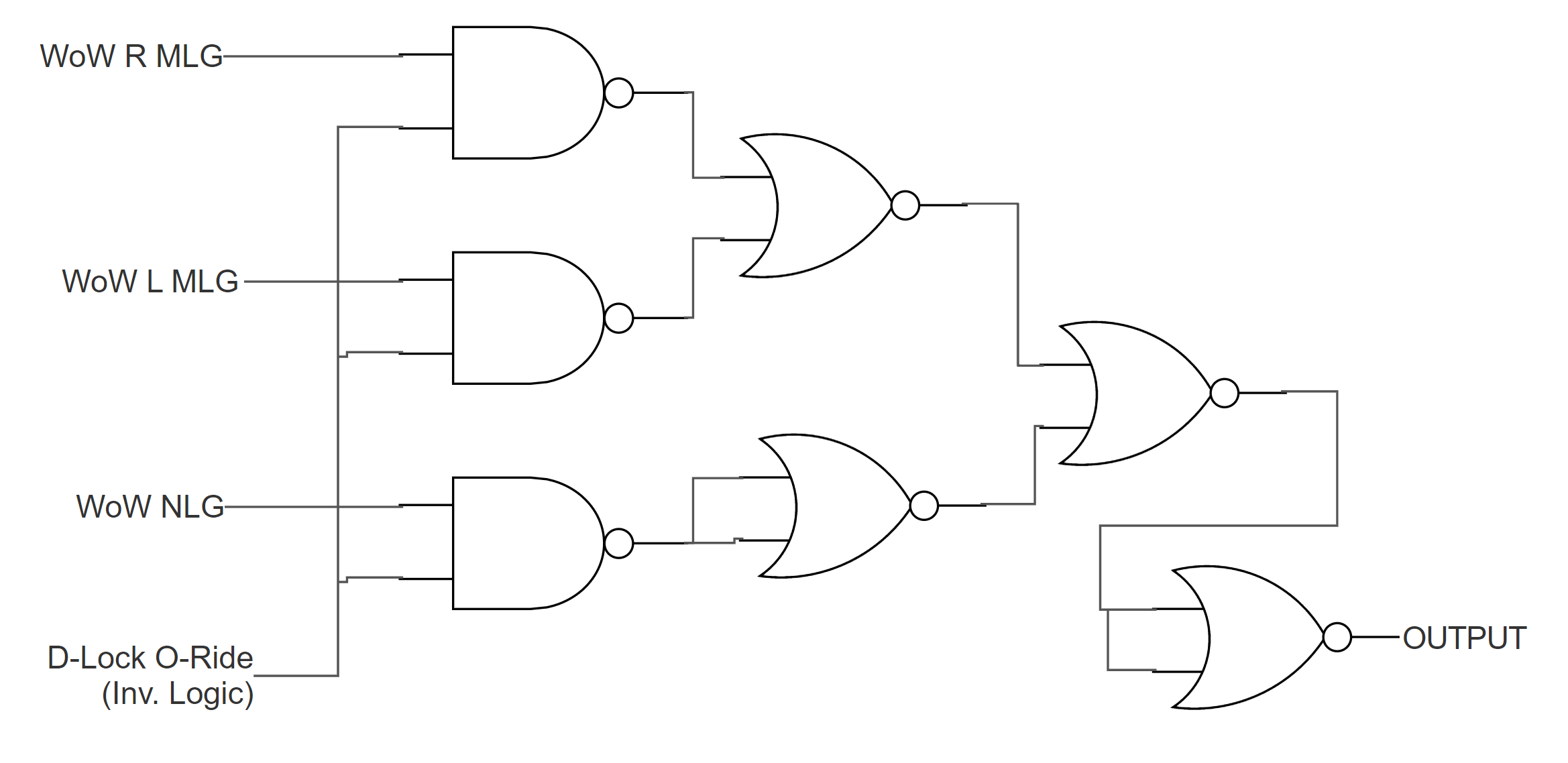
I'm also planning to use the downlock override button as part of the logic circuit. Whilst the downlock override button will be connected to a pin on the arduino, to send the signal to the game via DCS BIOS, I'll also use signal to override the WoW logic and remove the baulk pin. As the Arduino works by pulling the digital pin upto 5V and grounding it via the button, this logic is inverted if I take the 5V digital pin to the logic circuit (So 1 is 0V and 0 is 5V, if that makes sense). This is the truth table; The above table has 1 on the downlock overide being ACTIVE (i.e. pushed), where the actual d-lock signal is LOW. Working through the Karnaugh map, this results in a Boolean formula of OP = (RMLG x DLock') + (LMLG x DLock') + (NLG x Dlock') - where the apostrophe indicates the inverse signal. As previously mentioned, the d-lock signal is already inverted as a result of how the arduino pin works (grounding 5V makes it active), so we don't need to invert this signal after all! As a logic circuit, using one 74HC00 quad NAND chip and one 74HC02 quad NOR chip (which I have kicking around) looks like this; Clear as mud?! I could dick around and do some of it in code, but I'd need to use two chips any way.
-
A-10C Landing Gear Handle Baulking Pin
CorporalCarrot replied to CorporalCarrot's topic in Home Cockpits
I was looking at doing something with the code, but I'm using a MEGA on that panel with plenty of spare pins, so I'll just use the LED outputs and a 74HC00 quad NAND gate to control the logic. I'm planning on using a solenoid to baulk the landing gear handle, if I can find one that reasonably efficient (and not get hot). I can just use a transistor and a FET to switch the solenoid (if the one I source doesn't have a logic level input). Thanks Crash test pilot. -
A-10C Landing Gear Handle Baulking Pin
CorporalCarrot replied to CorporalCarrot's topic in Home Cockpits
Are you sure this is for the A-10C? This is all that is listed under External Aircraft Model for me; Control Reference: A-10C: External Aircraft Model (8/8 displayed) Formation LightsA-10C/EXT_FORMATION_LIGHTS Commands: IntegerBufferServoOutput Integer Output: Formation Lights void onExtFormationLightsChange(unsigned int newValue) { /* your code here */ } DcsBios::IntegerBuffer extFormationLightsBuffer(0x12ce, 0xffff, 0, onExtFormationLightsChange); no data yet Left Position Light (red)A-10C/EXT_POSITION_LIGHT_LEFT Commands: LEDIntegerBuffer Integer Output: Left Position Light (red) DcsBios::LED extPositionLightLeft(0x11bc, 0x0800, PIN); no data yet Left Speed BrakeA-10C/EXT_SPEED_BRAKE_LEFT Commands: IntegerBufferServoOutput Integer Output: Left Speed Brake void onExtSpeedBrakeLeftChange(unsigned int newValue) { /* your code here */ } DcsBios::IntegerBuffer extSpeedBrakeLeftBuffer(0x12cc, 0xffff, 0, onExtSpeedBrakeLeftChange); no data yet Left Strobe LightA-10C/EXT_STROBE_LEFT Commands: LEDIntegerBuffer Integer Output: Left Strobe Light DcsBios::LED extStrobeLeft(0x11bc, 0x4000, PIN); no data yet Right Position Light (green)A-10C/EXT_POSITION_LIGHT_RIGHT Commands: LEDIntegerBuffer Integer Output: Right Position Light (green) DcsBios::LED extPositionLightRight(0x11bc, 0x1000, PIN); no data yet Right Speed BrakeA-10C/EXT_SPEED_BRAKE_RIGHT Commands: IntegerBufferServoOutput Integer Output: Right Speed Brake void onExtSpeedBrakeRightChange(unsigned int newValue) { /* your code here */ } DcsBios::IntegerBuffer extSpeedBrakeRightBuffer(0x12ca, 0xffff, 0, onExtSpeedBrakeRightChange); no data yet Right Strobe LightA-10C/EXT_STROBE_RIGHT Commands: LEDIntegerBuffer Integer Output: Right Strobe Light DcsBios::LED extStrobeRight(0x11bc, 0x8000, PIN); no data yet Tail Strobe LightA-10C/EXT_STROBE_TAIL Commands: LEDIntegerBuffer Integer Output: Tail Strobe Light DcsBios::LED extStrobeTail(0x11bc, 0x2000, PIN); no data yet Scratch that..... I 'updated' DCS-Bios several days ago by re-installing with the latest version of DCS Bios from Github, but I went to check plugins (to download another module) and I noticed that you update the modules from there..... FML I see the WoW sensors now....