zinhawk
-
Posts
61 -
Joined
-
Last visited
Content Type
Profiles
Forums
Events
Everything posted by zinhawk
-
I thought I had it right the first time... dang. We did have a shutdown at idle but the more I think about it yet again the valve at the tank (trailer tank) was in shutoff mode and starved the supply. Thanks for the clarification and knowledge reinforcement.
-
That is a correct assumption. The fuel pumps on the engines are strong enough to self feed once started. They are mechanically tied to the engine compressor through the gearbox so if the compressor goes faster, the pumps go faster, more fuel, etc. As far as being able to prime the lines enough for startup, I'm not 100% sure. I am reaching way back to Tech School without direct references handy. I believe you would risk cavitating the pump so you would need something to pressurize the feed before hand. Hence the meat of the current discussion. That seems like a reasonable conclusion. The APU has nothing to do with engine start other than air supply to the starters. Taking it further, with crossfeed on, you should also be able to start #2 in the same everything-off-except-battery, air connected, scenario just as Diesel described in post #16. My take away so far is the DC pump is simply a system primer/as well as a direct feed to the APU. Fascinating. Everything past the engine pylon hookups is mud to me. I look forward to learning more. Addendum: A recent oopsy on test cell reminded me that even though the engine can start up without boost pumps, it is more of a function of residual fuel in the lines the engine pump sucks out than able to take it from the tank itself. The motor will die at idle without pumps on :smilewink:
-
Short answer is they are all right.:) Depends on the maintenance unit and if the guy who painted it gave a little that day. Even some of our jets have slight variation in cosmetic appeal. Engine guys don't usually paint in our neck of the woods or they would be all the same :happy: I can see why APU isn't greened up on RPMs on most because it is an all the way on (100%) or off kind of device. Any deviation outside of startup would mean malfunction. Too bad I missed taking a pic in the jet today. If I had to find an existing picture that is most like what we have it be this one:
-
Thanks. I don't know the lbs per percent either. I tried but that is beyond me :) I'm just a monkey with a wrench and limits to live in or its my a**. Take a slightly underperforming engine and multiply it by 2 and I imagine its a little more than insignificant if the the Air Force and GE is worried about it. I would be curious if a mod or some sort of alpha build could be given to a pilot to test it out. Perhaps it is enough to slow down energy loss in manuevers.
-
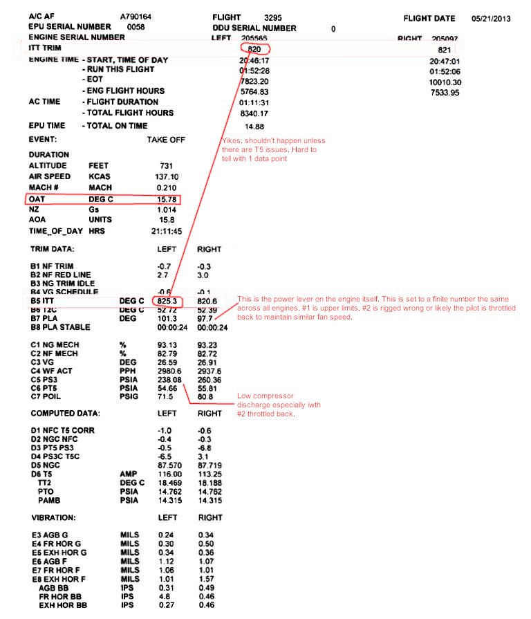
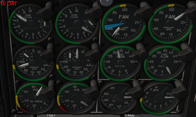
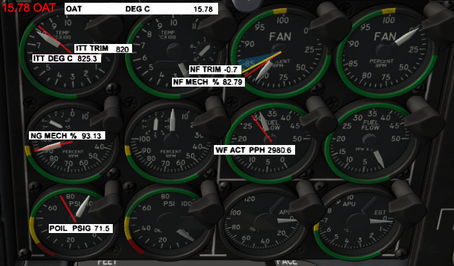
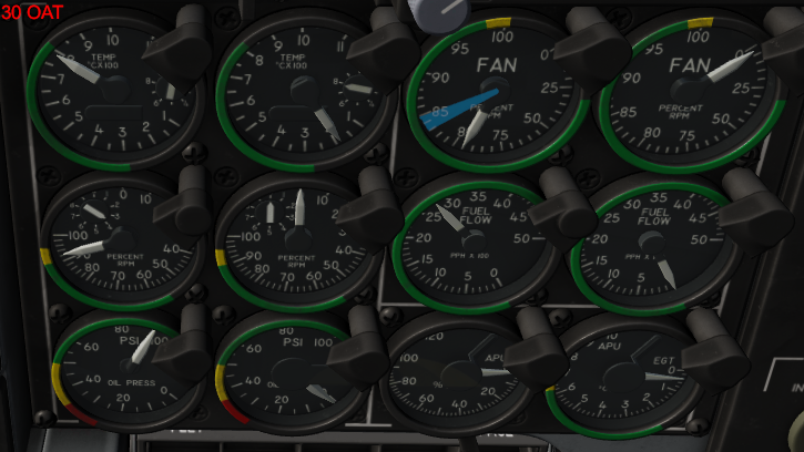
Soo I checked the numbers, talked to experienced colleagues and did some tests.. I edited post #1 to be a little more specific, but those with legitimate access can look into the documents and find the same fan speed trim chart to verify I am not talking out of my a**. New engines, old engines, test cell, installed, all are trimmed to this chart (EPU calculates sensor data to figure out where the engine should be along it). Based on Outside Air Temperature (OAT), engines MUST produce target fan speed as this is the primary indication of proper thrust on a high bypass turbofan. ITT is more of an indication of efficiency, how much fuel it takes, at producing said fan speed. A 790 ITT motor and an 830 ITT motor are both producing the same thrust (core output is marginal) at any identical fan speed. The 790 motor is just better at it and will last longer. Henceforth I am ignoring ITT in further discussion of thrust except for comparison sake or explaining fuel flow relationships. Why am I bringing any of this up? If Fan trim (NF Trim, NFTR) is a few percent under target, performance recovery is a concern. If GE is concerned with that narrow of a margin, it is probably important to thrust output and achieving that ~8900lbs. The Test The chart is based on static engine runs so we will mimic that. A simple "trim pad" simulation is to set the desired OAT in Mission Editor and setup a hot start. Upon starting the flight, shut down an engine, stand on the brakes and giv'er the beans. There are some assumptions being made when looking at expected performance: 1. Bleed air and generator effects on the engine are not modeled. The switch does nothing to performance. It is not uncommon to lose ~1-1.5% fan speed on static runs with bleed air and respective generator on as they sap the power output of the compressor. This is why the trim checks are typically done with these items off. Now, even though these are on in flight, data suggest most of the loss is recovered from ram air into the fan inlet as the aircraft moves. This is also not modeled as far as I can tell. So it's a wash and negligible. I will look for "bleed air off" speeds. 2. Rectifying gauge data and direct digital data we use for engine monitoring. In the real world there is some acceptable slop in analog gauges displaying digital information. Unless ED models gauge variance, in the perfect video game world I'm expecting gauges to be direct digital information. Factoring the chart and averaging real world data at different OAT, I expected fan speed to be somewhere in the blue area or a little less. The fan fall off per OAT is good, but fan speed looks to be about ~4-5% below normal across the power band. This doesn't seem like much but it is well outside usual NFTR and would be cause for grounding in the real world. Looking at the example engine data shown before, I decided to focus in on #1 since #2 is in a throttled back state. The 15.78 OAT picture has red lines for real engine reference. The DCS engine should still have fan brought up ~2-3% to be within limits. Some minor thoughts on gauge information that isn't really about performance but rather increasing representative data accuracy. 1. Fuel flow is kinda high but within limits. There appears to be a direct relationship between fuel flow and fan speed. This is incorrect. The fuel control is mechanically tied to the compressor and thus should have a flow rate correlating with core speed until it reaches the T5 limit at the top end. Once there fuel rate should stabilize with ITT no matter the OAT. 2. I wasn't watching oil on spool up but ditto oil/core relationship. Oil pressure at max is too high. 95 is max allowable and typically only seen with cold starts. Once warmed up, pressures soak back to look more like the example engine at max. 4. There should be a delay in fan spool up after core spools up in both motor and normal starts. Fan will stop rotating before core on shutdown. 5. A good average ITT is 820 but that is here nor there. A big item is the fuel override switch. This doesn't do anything in DCS. It should turn off the T5 and unlock full potential power of the engine with no restraints. This is where you should see the 9,060 number. I haven't fire walled an unlimited engine to know what kind of fan speed you obtain but if I had to guess it would be ~3-5% maybe. Core and all other gauges should be approaching or exceeding maximum values. It would be nice having a working get out of jail free card. That is my 2 cents.

-
Right. On cold days which we typical run we see fan speeds in the ball park of 86~85. Attempting to recreate cold day conditions and altitude similar to home station in DCS can't get it above 82 unless you make it really dense. The expected TEMS output would in the neighborhood of NFTR -4. That is extremely unsat in real world. That is what got my attention in the first place. I also attempted to recreate the flight data in the TEMS picture. I can go into detail later on methodology but the DCS engine runs a few percent less than even that example. A few percent is outside the NFTR margin of error and the engine would be water washed and or uptrimmed. You might get good airspeed but if you don't have proper sustained thrust while maneuvering that would compound your issues with drag. Also there are oddities with the Trim picture provided in the previous performance threads that indicate the example data provided is not that reliable, but I was going to compare RW data to see how much I want to tug on the thread.
-
Thanks. I did read the two long posts discussing engine performance and saw references to the aircraft and pilot manuals and a legit TEMS picture, but I did not see any direct reference to what engine troopers actually use for performance checks other than a vague reference to " the engine manual". At great risk of ripping off a band-aid I was curious as to what ED is using for reference other than the single TEMS picture. I am currently a 2A651C and the TF-34 is my baby. Probably for the forseeable future until Congress gets its way with it. Over the last 3 years I have fully rebuilt, tested, and maintained this engine. While I am not yet a fully seasoned veteran, it is a simple engine and a few patterns have been the same across trimming multiple engines on test cell and the wing. Doing a trim pad check from memory in DCS I noticed some inconsistencies with real world experience. However, I will look at the real data we have to compare and investigate further. Plus if ED is using direct engine books for performance targets than that is enough for me. I can help clarify source material language if need be because the engine books do suck (no pun intended) in terms of reading quality.
-
Does ED have access to the 2J-TF34-116-9? or the 1A-10C-2-71JG -2 series? Fan speed charts are the same in these books in the Fan Trim chapters. 71JG-2 is easier to read.
-
I've only been around the aircraft a few years so I don't know all the innerworkings of why. I do see our structures guys take them off all the time for maintenance purposes, and it would certainly red X it for combat capability, hence the not normally part. I'll let structures argue whether or not it can be made flight worthy with caps. Not my area of expertise. I could help with engine function though :thumbup: I was looking at it from a physically possible vs normal combat behavior standpoint. Ditto Pave Penny, I get the suite argument, but it is pointless lugging around a non functioning portion of the module. All this is operating without any knowledge of the planned A-10C 2. So wait and see. I just wanted to mention this while it is more or less in the development segment. Upon further reading of older posts I did see the Pave Penny aspect talked about that I missed so sorry for that.
-
Coming primarily from the Hawg, then spending a little time in the Hornet, I am having the most fun in the Harrier so far. FARP work is a blast, especially with the Marston Mats mod. I know nothing of the Harrier so I am oblivious to any "systematic shortcomings". Some things are easier to use in the Harrier versus the A-10C, some not. I am still struggling with not using A-10 HOTAS switchology from muscle memory. Overall I've been surprised and impressed with the Harriers capabilities as is. The Hornet is a fun all rounder, good at everything-master at none, but I've had more fun with the AV-8 challenge. Even your f*** ups with a friend provide hilarious moments.
-
I haven't seen it talked about so maybe its one of those no brainers or too trivial to matter. In which case maybe that could be a reason to do it anyway! 1. The biggest is deletion of the Pave Penny pylon. I don't know if this is factored into the drag model, but no unit has had the pylon on in some years. It is as about as useful as man nipples dangling there with the TGP. Plus removing it is proof you can put lipstick on a pig. 2. If ED wanted to make the Pave Penny functional with the A10C 2 (don't see why) and retain the pylon, at least make it removable and/or with the other 11 stations a la Hornet. Are the pylons removed normally? No. Can they be? Yes. It would be neat to see and "feel" what a clean A-10 would do.