xray20
-
Posts
161 -
Joined
-
Last visited
Content Type
Profiles
Forums
Events
Everything posted by xray20
-
NTTR info and mission by the 476
xray20 replied to Stuka's topic in DCS: Nevada Test and Training Range
Steerpoint List Excellent Work. Thank you. Does anyone have a list (better yet an excel sheet) of the steerpoints and their numbers ? Matt -
NTTR Local Area Reporting Points Not so much a mission as a template for those interested in building real-world missions. I have taken the Reporting Points detailed in the NELLIS RED FLAG IN-FLIGHT GUIDE 2014 and placed them on the map as IP objects. They will come up as steerpoints on the A10-C. For those who have not read it, I recommend the guide, which can be found at http://www.vusaf.us/RFN14/resources/In-Flight-Guide/RFN14IFG.pdf It gives some insight into the precision and discipline required to fly Red Flag ops. I especially like Jettison Hill - a place to drop hung ordnance before landing at Nellis. Cheers Matt NTTR Local Area Navigation Points.miz
-
Google Map of real bombing ranges I am building a base mission file based on real world imagery which has objects placed on the ground where at the moment they are just flat images. I'm absolutely amazed at how many ranges and targets there are out there. Some are quite mysterious. I have found tanks in revetments, numerous airfields scratched out of the sand. There is a CAMOUT facility (Combined Arms Military Operations in Urban Terrain) - an entire village made out of containers and junk- a few miles to the north west of Creech. A disused railway siding seems to have containers placed on the track taking the place of carriages. Some circles, which I found, turn out not to be targets, but marks in the desert to assess the effects of underground nuclear detonations. I have saved my findings on a google map. https://www.google.com/maps/d/edit?mid=zitToDztQ4m0.kIOfWAq5hAKA&usp=sharing Please PM me if you have found something interesting and would like to add it to the map and I will include it or add you as an editor. I have not yet had a chance to see if all of the objects seen on google are visible on the NTTR map, but so far everything I have found is there. I have also been using the Nellis Red Flag 2014 Guide (link available elsewhere on the forum) and entering the reporting points (FLEX, NIXON etc.) as IP points. These give a good idea of where the action is to be found. I will post my .miz file when its good to go if 476th don't beat me to it. Cheers Matt
-
My experiments with acid etching have not been successful so far. The problem with the inkjet printed transparency not being sufficiently opaque to be an original label is the same problem when trying to expose photo-resist. The UV light bleeds through the black bits and partially exposes the photo-resist, so it won't develop properly. I'll try with some different timings and see if its any better, but I fear this approach is a dead end. Meanwhile my wife is not talking to me as I spilled ferric chloride in the Christmas gravy. :pain:
-
Public inquiry. What is your PC video card?
xray20 replied to Chizh's topic in DCS World 1.x (read only)
GTX980Ti on a Matrox THTG DE -
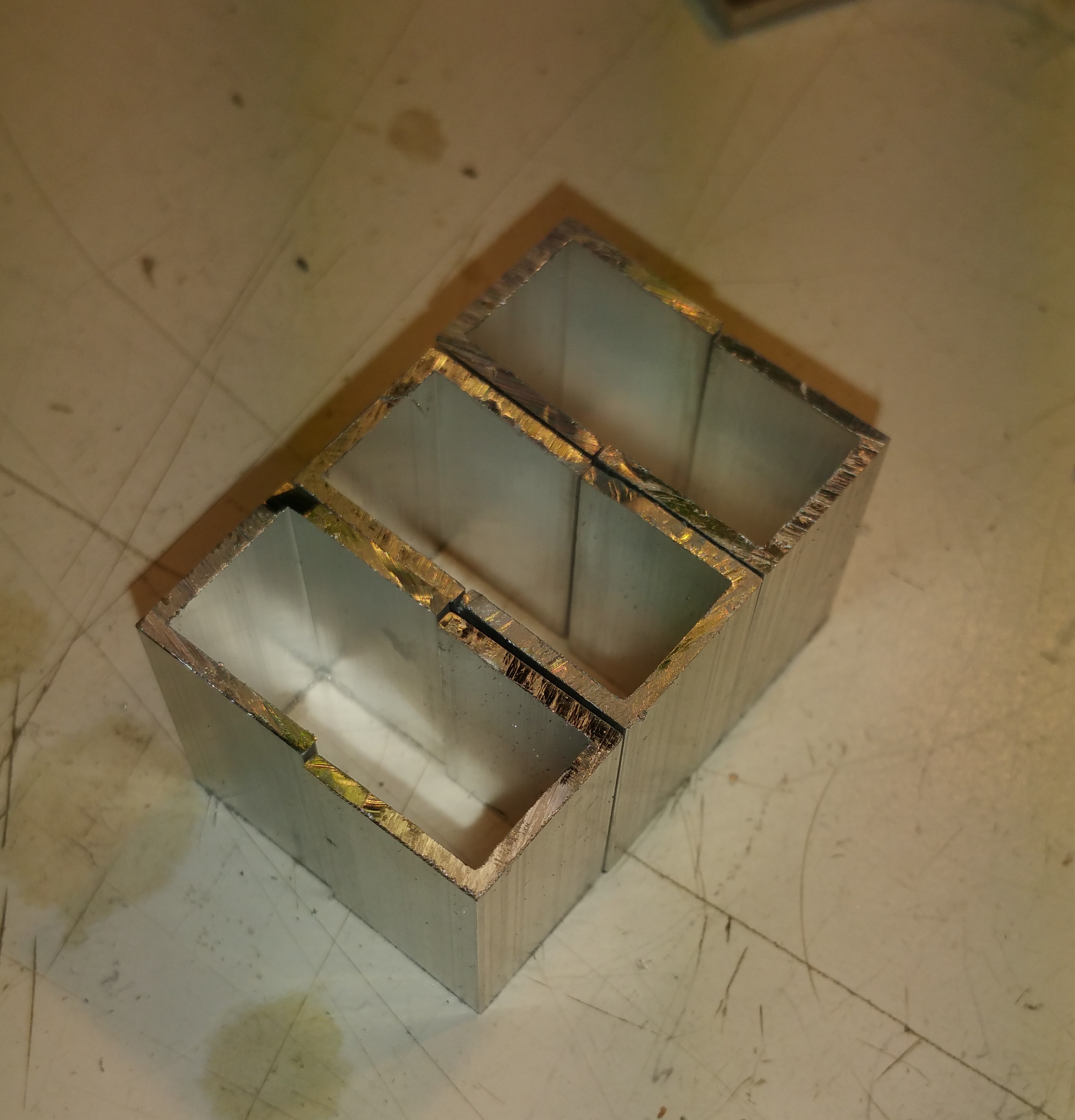
I have just tested with printing on inkjet acetate and (just as Warhog said) the ink is just not dense enough. I tried two passes, loading up the acetate with as much ink as it could handle without running and its better but still not good enough. The brass sheet arrived today. If I can get some sodium hydroxide on Christmas Eve I'll try etching. I wonder if the problems with ink density will also apply when I'm trying to expose the photosensitive film. BTW I found some aluminium channel at my local hardware shop (B&Q). I glued two pieces together to make a box. Its about the right size for the annunciator frame. Better than any box section aluminium I've been able to find. Happy Christmas Matt

-
Nice job. I would be happy with that. I have ordered all of my parts. Acetate, 0.1mm brass sheet, photosensitive film, photosensitive aerosol. Hopefully it will arrive before Christmas. I'll report on my progress.
-
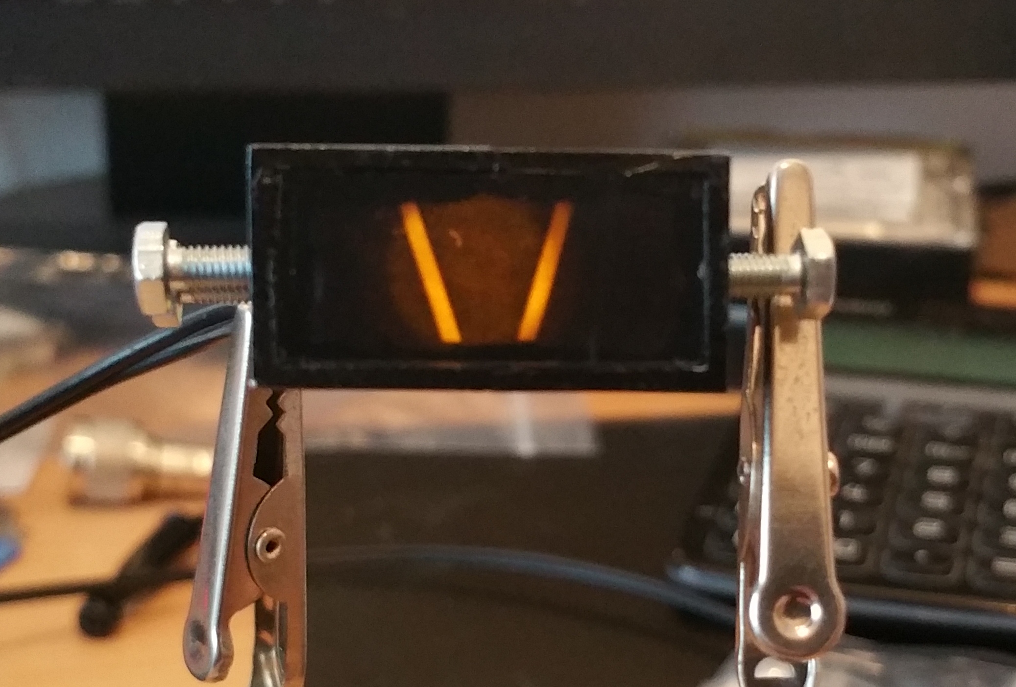
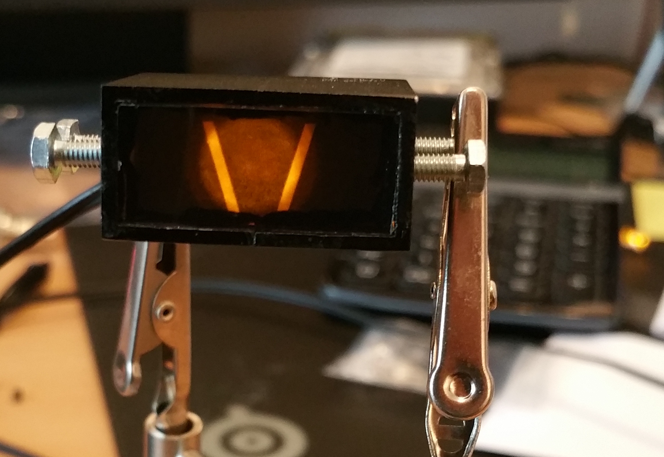
Very Nice. But the problem with A-10 annunciators is that the letters are lit on a black background. The inverse of this set-up. The layered construction is something I will follow though.
-
Yes, I want to use metal sheet. Its perfectly opaque so it can be really thin (< 0.1mm) It's the same thing. Circuit board is only metal film stuck to a board. It etches through perfectly. I think the acid etcher (Ferric Chloride or something less nasty) will cut through copper, brass or steel. I'm thinking about how to mount the etched masks in the bezels now. Maybe clear epoxy resin?
-
Photo Etch? OK, I'm going to try something here. I think it may be possible to make these using a photo etch technique. I think it will be possible to make masks using photoshop or similar print them on Inkjet acetate and etch thin brass sheet. It will be necessary to make webs on letters like O and P like a stencil so the centres don't drop out. Have a look at this.... I have just ordered some photo resist spray called POSITIV 20 available in the UK from Farnell for £10. http://uk.farnell.com/kontakt-chemie/positiv-20-200ml/positive-resist-positiv-20-200ml/dp/801010 The developer and etcher are available from local electronics stores (Maplin) and are the same as used for PCB manufacture. 0.1mm brass sheet is available from EBay. I'll let you know how I get on Matt
-
Thanks John, So no way to do this without an engraver? This looks like an expensive proposition. I have just had a look on Ebay and suitable machines look like they are going for many hundreds of pounds. What do you use?
-
Now I have LEDs working through Arduino and DCS-BIOS, I want to make some backlit annunciators like 'Take-off Trim' and 'Nosewheel steering' etc. I have had a look through the forum and can't find much detail. How are you building these annunciators? Specifically how do you make the transparent lettering with the dark background? Cheers Matt
-
DCS-BIOS Does what it says on the tin! I just want to say thanks to all the contributors for the great work on DCS-BIOS. I got my Arduino yesterday and had seven cockpit lights working within about 3 hours. Its very encouraging and has opened up a whole new set of possibilities for the cockpit. I have never used an Arduino before and the setup was very straightforward. I am an engineer by profession, so I am used to setting up systems, but nonetheless I had no issues following the excellent documentation and pre-made setup code. If I were to add anything to the documentation it would be about the diagnostic lights on the board (not sure if all boards have them) but the action of the TX RX lights and the flashing status light now give useful clues to what the board is doing (or not). I'll post my progress on my cockpit thread once I start to build the Arduino components in. Cheers Matt
-
Traffic is traveling in both directions on each of the dual carriageways of I95 near Creech AFB. As it doesn't appear to be doing this on the dual carriageway east of Vegas, I assume that this is a programmable feature. It's great to be able to comment on such detail!
-
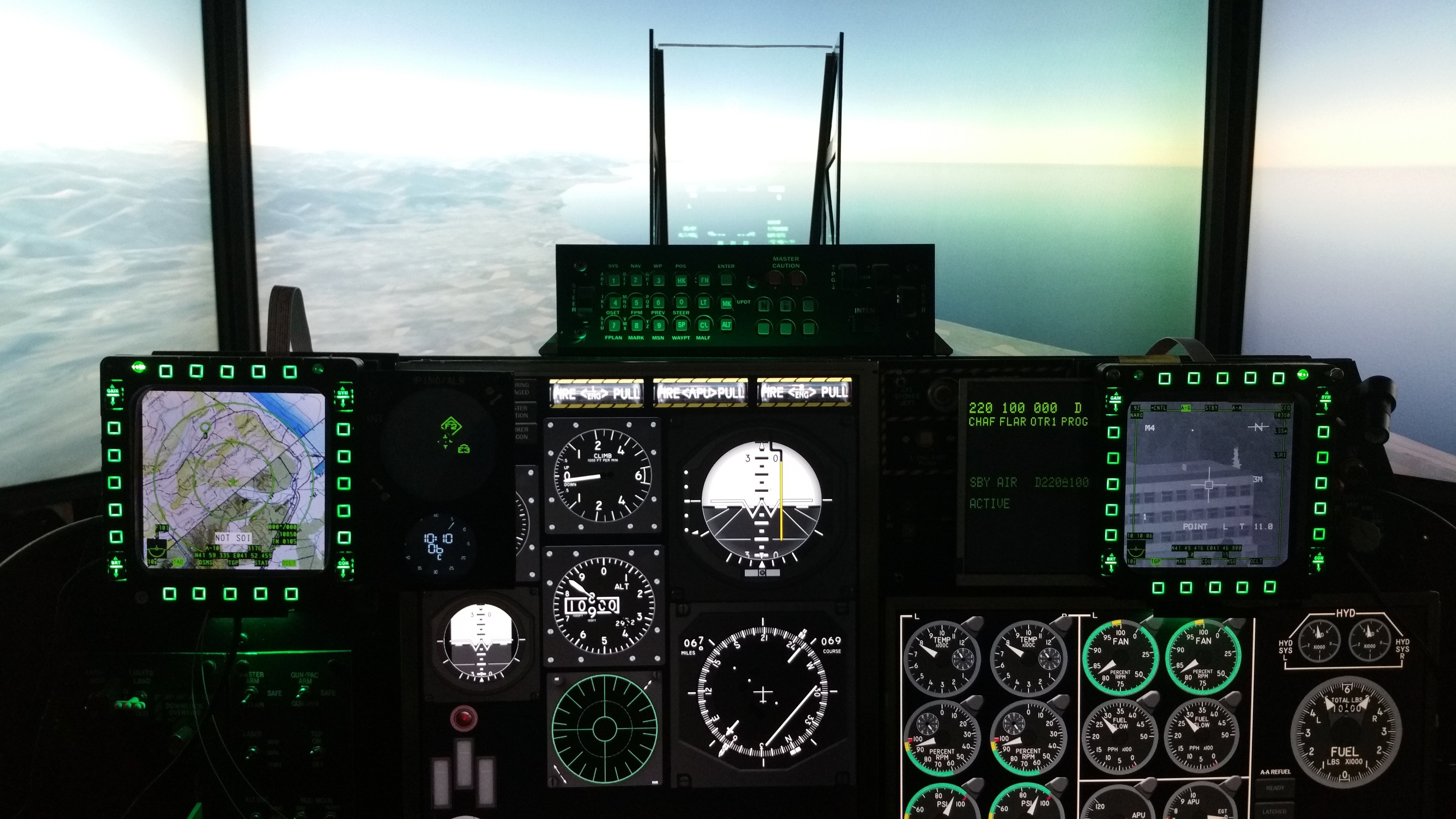
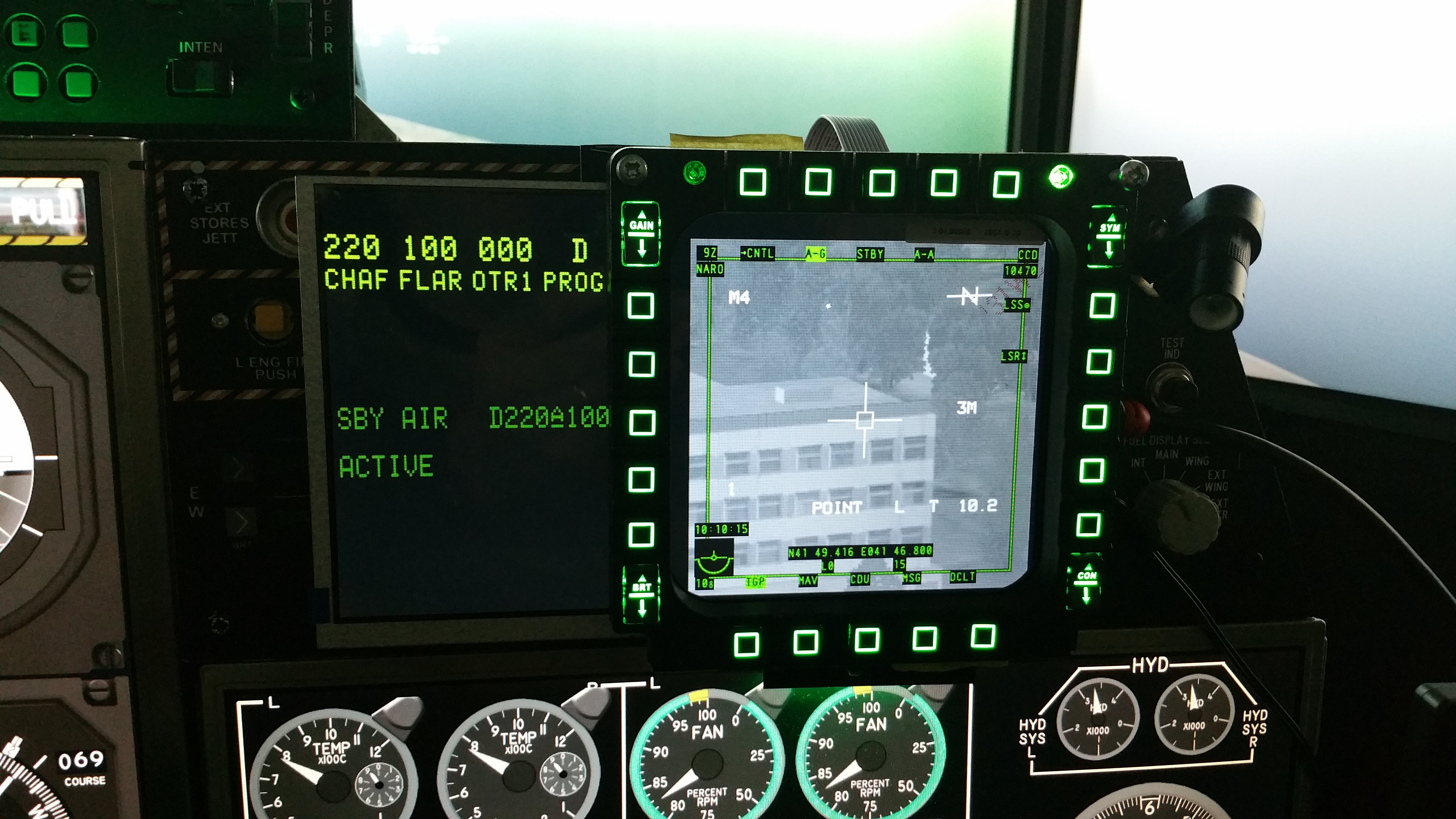
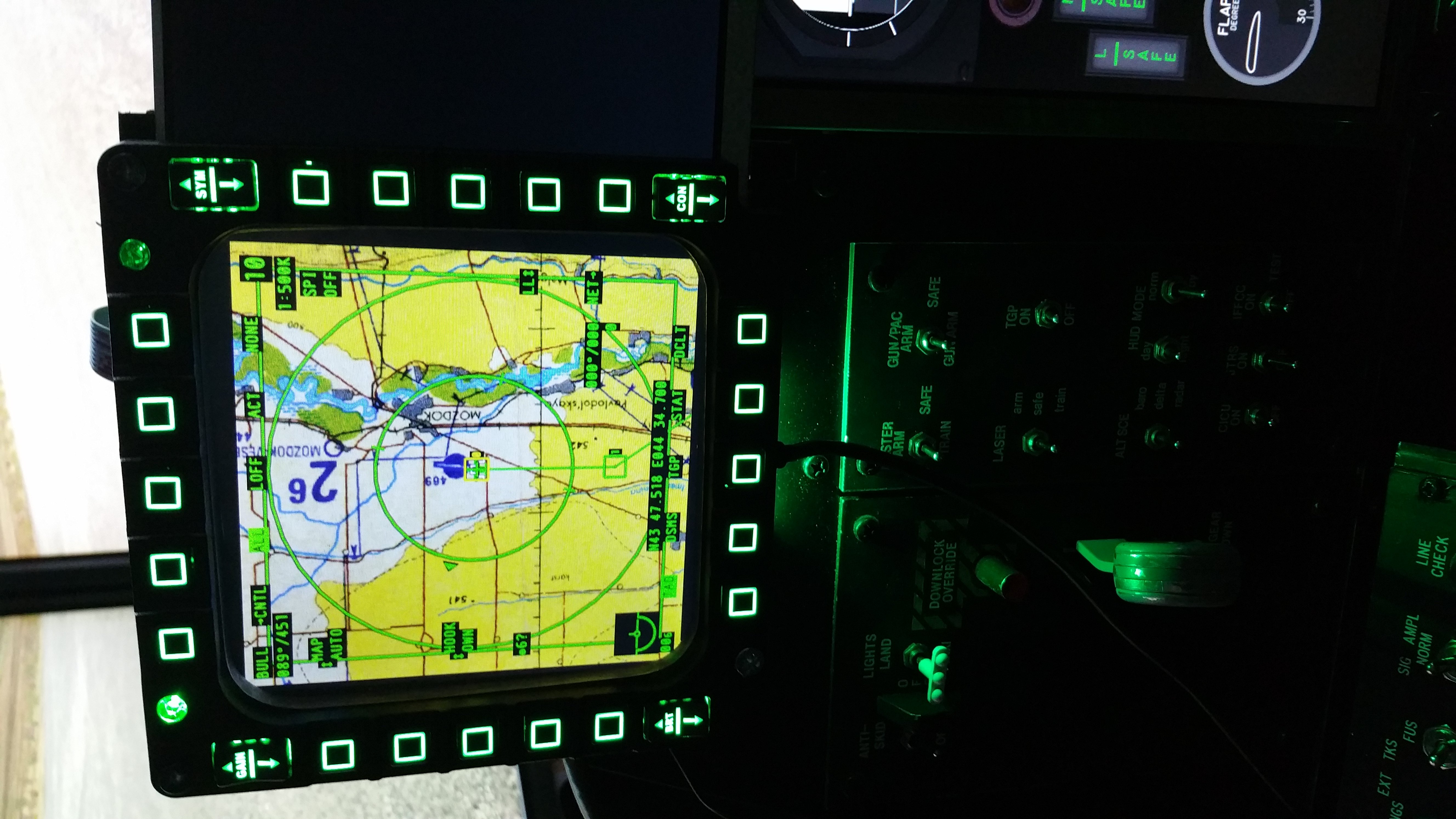
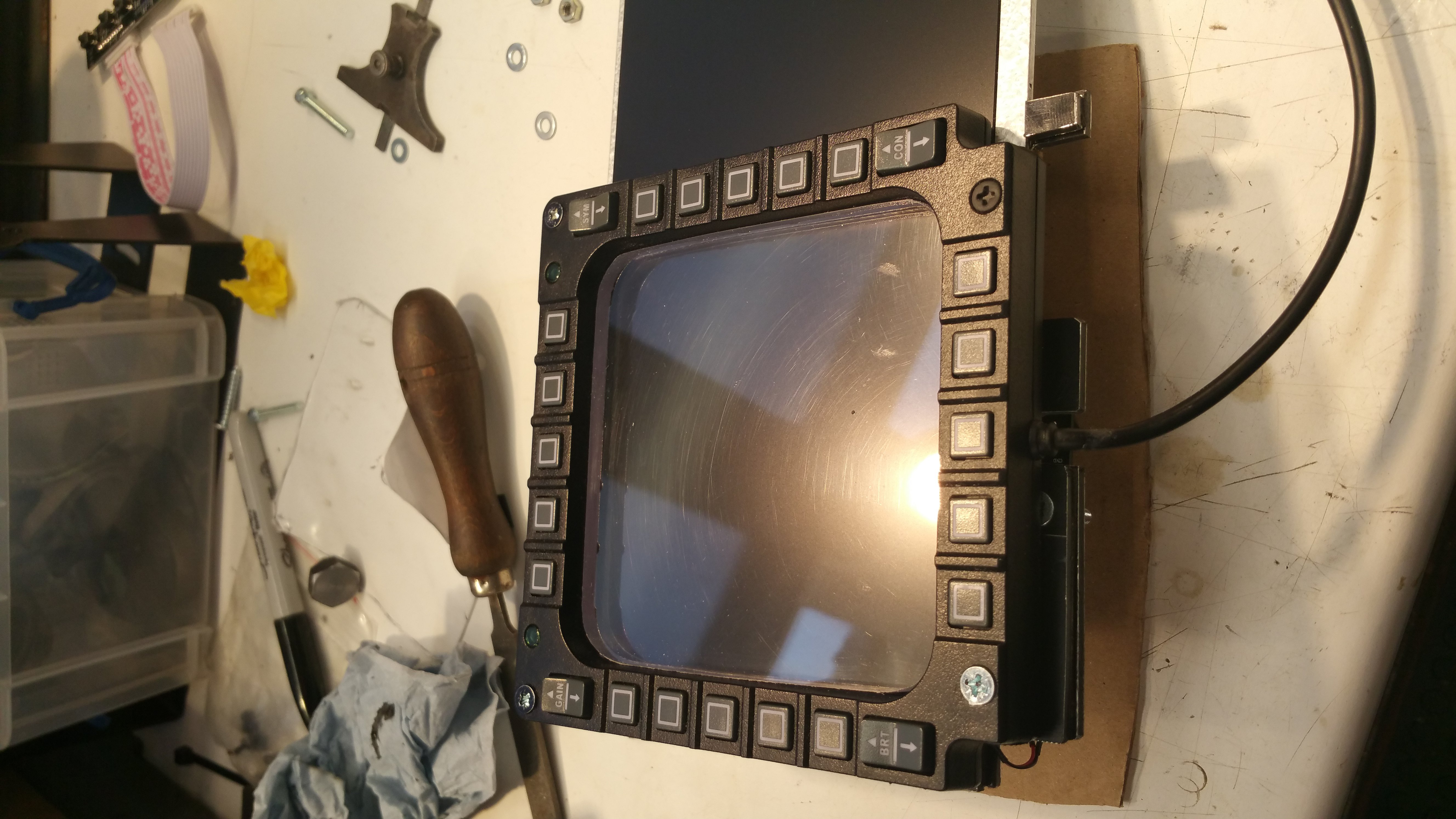
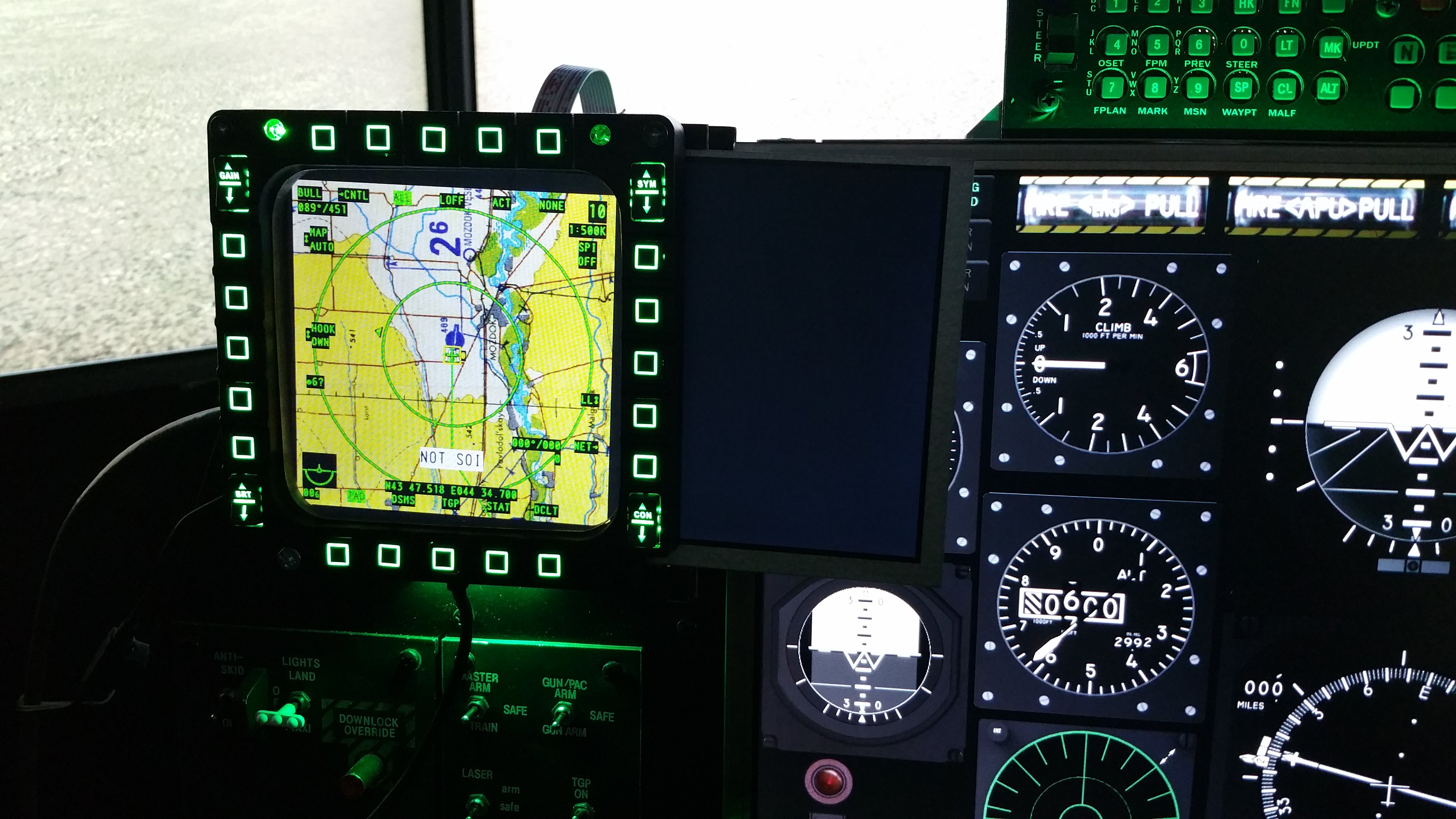
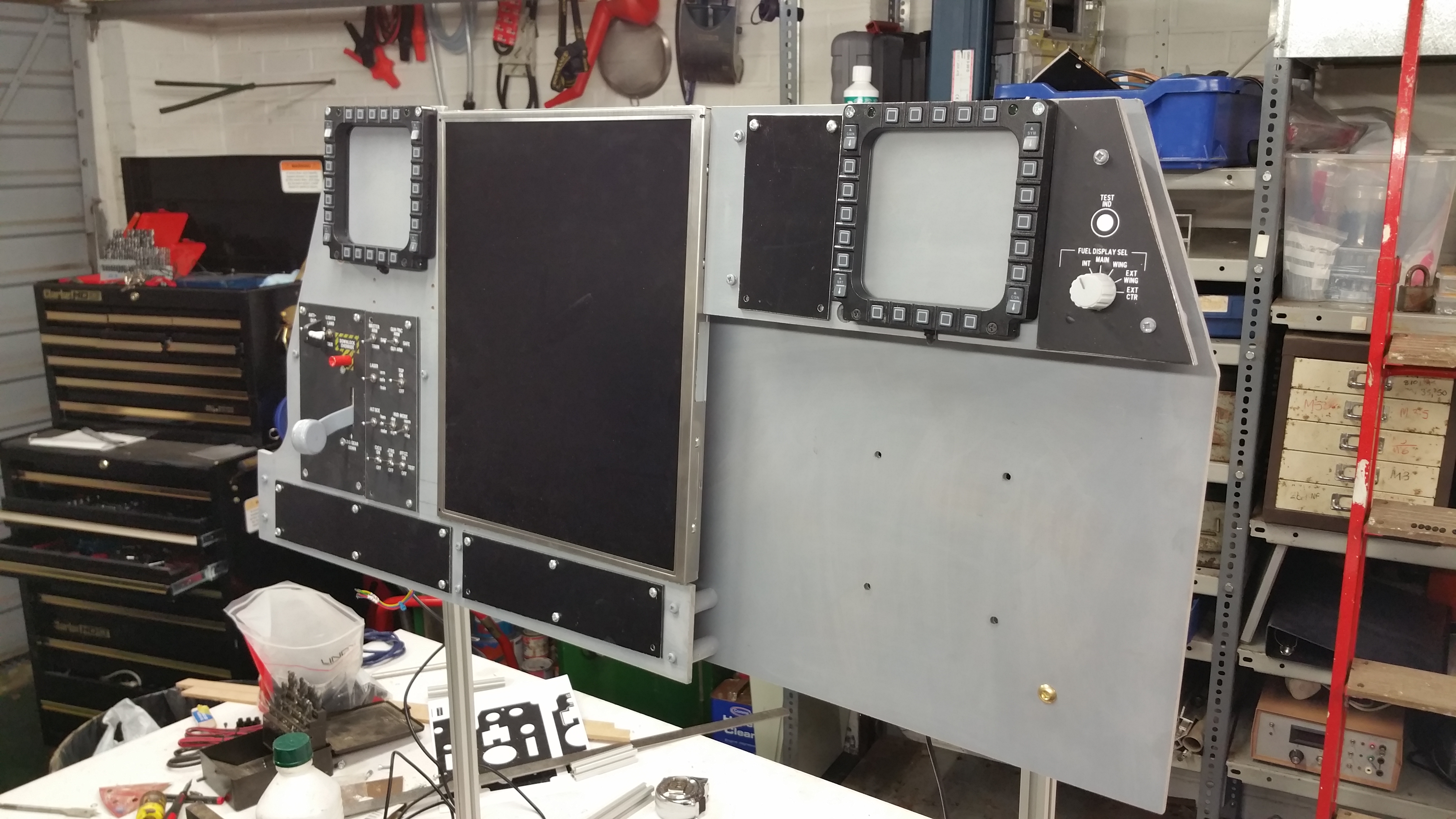
Right MFCD and RWR working Good progress this week. I got the RWR panel working with the part of the screen that overhangs the Left MFCD and the Right MFCD is in place for testing and is working well. The CMSP and CMSC displays fit well on the Right screen overhang. The surprising thing is how much better the simulation works with the MFCDs removed from the big screens. The static MFD images really fixed the world image in place, now they are gone the sense of movement is much better. I made myself feel quite sick - which is great! Next job is to set the displays properly in the front panel and shift the Helios instruments and indicators which are now covered by the new screens so I can see them again.
-
Sorry, bit of a tiny thumbnail. Here's a better one and the link to Ebay http://www.ebay.co.uk/itm/351532328545?_trksid=p2057872.m2749.l2648&ssPageName=STRK%3AMEBIDX%3AIT
-
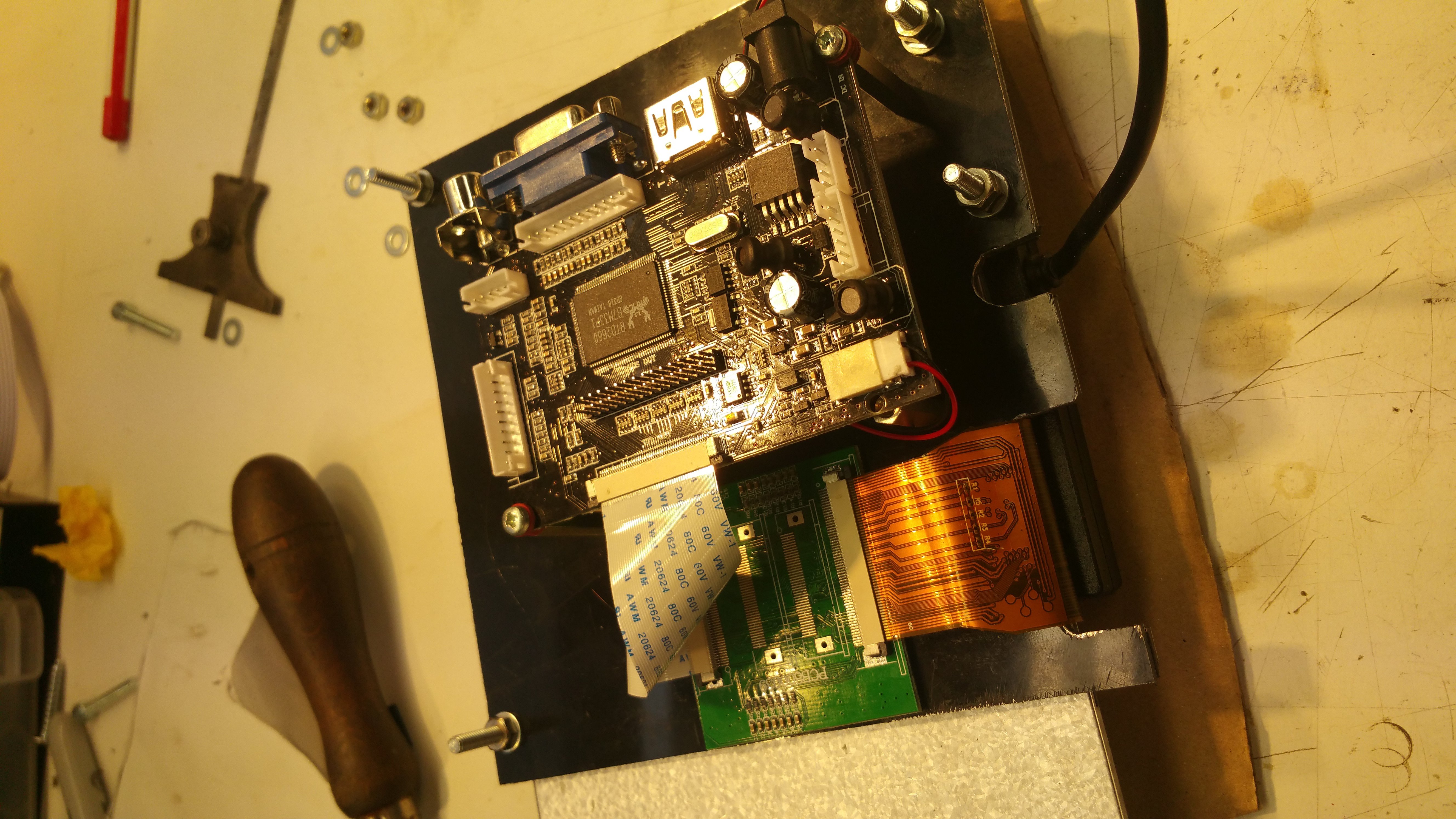
I have just upgraded my graphics card to a 980Ti, so I got some spare ports to connect up the MFCDs. I thought I'd try the SainSmart 9" TFT LCD 1024*600 Display + Monitor Driver HDMI VGA for Raspberry Pi from Ebay UK, at £43 it looks like a bargain and its working out OK too. I have built a small chassis to hold the display and the Cougar MFCD sits on top. The electronics for the display are mounted on the back of the chassis. I have cut a piece of 10mm clear plexiglas to fit in the Cougar frame to bring the display surface forward. The display is 16:9, so I'm going to export the RWR to the portion of the screen that extends from the side of the MFCD frame. The second display is on order so I can start work on the Right MFCD at the weekend. Matt
-
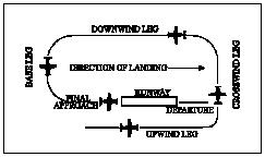
Can someone please clarify the rules about crossing runway axes when on approach or in the circuit? After having a couple of near-misses with multiplayer and AI aircraft while crossing the line of the runway while entering the circuit, I began to wonder what the real world rules are to prevent this. I checked Wikipedia and the FAA diagram (attached) doesn't help as it shows an aircraft on the crosswind leg apparently crossing the departure vector.
-
On 6th April 2003 a C130K of the 314th Operations Group out of Little Rock AFB was the first aircraft to land at Baghdad International Airport during the second Iraq war. The co-pilot Maj Ray Campbell having a few minutes to spare while the Aircraft was being unloaded, went into the airport terminal and found the pilots lounge on the second floor. He removed this plaque with his penknife and took it home as a souvenir. It sat on the drinks cabinet at his home until he was sent on overseas deployment to RAF Mildenhall in the UK. He went on ahead while his wife cleared their service apartment before leaving to join him. It was put in a box (by mistake) and sold with two ornamental lampshades and a George Foreman grill to a junkshop by the contract cleaners. After lying in the shop for 3 years you found it. And the rest is history...
-
It says Pilots in Arabic. I just googled it. Probably from a door to the pilots office (somewhere in the middle east) ......
-
I had some trouble with embedding YouTube clips in forum posts and it seems that a lot of other people do too. I couldn't find any thread on the forum which addressed this issue, so I thought I'd post one. When embedding you tube clips it is not necessary to put the entire URL between the tags. Just the unique code so: YOUTUBE]https://www.youtube.com/watch?v=4JDSQaKX48g[/YOUTUBE will fail, but YOUTUBE]4JDSQaKX48g[/YOUTUBE works. Matt
-
Like everyone here, I have been eagerly awaiting the release of DCS 2.0 and have been putting off any upgrades to the cockpit system in case 2.0 was not compatible with some element of the system. Today I finished the integration of 1.5 rev3 and I'm happy to say Helios and all of the other mods plug in and work exactly as with 1.2. Now, given development of the pit has been static for over a year, I'm confident that 2.0 will work and want to do some upgrades to take advantage of the fabulous improvement in the graphics. Pit Builders; I seek your advice in upgrades to the CPU and graphics to get a better frame rate and addition of HDMI/DVI ports to get the MFCDs onto the cockpit panel. Here's the video of my current pit build (DCS1.2) The detailed spec of the system is below. With 1.5 I'm getting around 45fps in free flight down to 25fps and below in complex scenes with other aircraft. The shadows of the trees paint in blocks in the distance which I suspect may be due to speed of the hard disk. Also I have run out of spare HDMI ports for additional screens on the main PC for the MFCDs (Helios is running on a second networked PC). So, in terms of bangs for the buck, what's do you suggest my upgrade path should be? Thanks Matt Intel i5-2320 CPU @ 3.00GHz Windows 7 pro 64bit 16GB RAM 1 x 1TB SATA HDD NVIDIA GeForce GTX 680 at 5760x1080 on Matrox THTG (port 1 ) 800x600 port 2 for RWR and CMSP 2 x Hagstrom USB108 for switches and Bodnar24 for rotaries Thrustmaster Warthog stick and throttle, Saitek pro rudder pedals. Thrustmaster Cougar MFCDs
-
Like I said on the YouTube intro, It was all from salvaged parts. The 55" NECs didn't cost me anything. They were scrapped from a job, as were the instrumentation screens (It helps if you work with screens for a living). As for the build thread, I did the bulk of the work over the Christmas 2014 break. By the time I got the technique sorted out I was doing two panels a day, so I didn't really have time to post anything. The whole thing from mark 1 (see my previous youtube video) to mark two took about 10 days of solid (my wife says obsessive) work I did photograph everything though. I could do a sort of post build thread if you are interested.
-
Have you tried the link at the bottom of the post? I can't see anyone's embedded YouTube videos working at the moment and there's no information why.
-
I have to admit I'm cheating on the HUD. I did have a design with a projector and mirror, but this is actually just a frame and a piece of acrylic. The HUD is on the main screen. The effect of looking through the acrylic gives it the appropriate framing and it looks pretty much as it should, but without lots of extra hardware. It took about two hours to make. Its all part of the philosophy of getting it to work as simply as possible without getting bogged down in details or huge expense.