rocketeer
-
Posts
751 -
Joined
-
Last visited
Content Type
Profiles
Forums
Events
Everything posted by rocketeer
-
Look at this. Kuky showed how to make the osb work. I tried it and made a push button work on one of the osb buttons via a Leo board for the a10c beta 1. http://forums.eagle.ru/showthread.php?t=59541 Try it.
-
If they don't have to be push pull but just latched push on push off type, then can we just put a pot in front of a push button, secure them together and have both pot and push button functionality?
-
Thats what I thought too, push pull and pot. But is there such a switch out there?
-
Feed, two questions. 1. Are you using CTS288 encoder? I'm checking to see if that is the one to get. I think most people are using it since it's sold at OC site so it's kinda endorsed to work. 2. Have you tried OC with A10C beta? Or just BS? I'm wondering if the beta2 has all the necessary lua files to make interfacing with SOIC work yet. I checked the device file and none of the devices are assigned numbers like in BS. Maybe we can just assign device numbers ourselves. I wonder what else is missing. If the beta is ready for SOIC then I'd get the OC cards so I can some of my switches working, else I'd continue building my panels for now.
-
At first I thought these volume like switches will be pots, then thought they may be encoders if they rotate round and round. Reading the manual and trying it out in beta one shows them as in-out swithces, rotating doesn't matter! So to build this panel should I be using small push pull switches instead of pots or encoders?
-
See post #3 by Feed. The MC can do 72 inputs And 38 outputs. But unless you have an old PC with printer port, you'd need to get the USB expansion card to connect the mc to your PC. One USB card can connect 4 mc. You can buy one of each for a start. It'd need a 5v source. If you don't have a 5v adaptor use one of the power cables in your PC. Just make sure you use the correct one.
-
Forgot to add they charge quite a bit for shipping and handling, but at about $4 for each knob, I took it, plus I only had to get one each. then I made like 8 more later. For MS91528-1F4G, they may have the type without the skirt base, which is required for one of the left bottom console panels.
-
Ok I got these two knobs from Allied Electronics. MS91528-1F2B MS91528-1B2B B means black. 2 means 1/4" size hole round and not D shaped hole. They are black, as gray ones are hard to find. If the diameter of the shaft is not right (too big or small for your pot or rotary switch), you can make a replica and drill the reqeuired size. Of course it's best the find the exact size and color if you can. I only use 1/4" shaft for my pots and rotaries, and D shaped, so I always look for these type of knobs hole type and size. Quite a number of knobs can be found in the link I gave above. Hope this helps.
-
Thanks guys. Hog_driver, I'd check you the part numbers from radio shack. they actually ship to you for free! Feed, check my post #143. Some knobs from here http://aviationsimulationgroup.com/AircraftKnobs.aspx Some other knobs I bought from online store, yet some I actually borrowed, made a mold, and returned them to the great friend. Some of these knobs I may have spare ones lying around. If you learn how to make mold and casting I can send one to you for the knobs that I have a spare. Then you can make a lot more for yourself. those that I found online I'd search for the site names and post here for you guys.
-
Some progress tonight. I've secured the toggles and push buttons on the panel sheets. Yet to do 1. Secure the pots and rotary switches which need to be secured on a separate board underneath to adjust for the height. Doing this way I don't have to saw the pots and rotaries neck. I can adjust to the height I want. Pictures next time. 2. Paint some of the knobs 3. Drill holes for some of the knobs, including the horizontal holes for the set screws to secure the knobs to the D shape shaft of the pot and rotaries. 4. Glue the panel sheets to the wood surface. So far these are all inputs, the easier part. Not doing the lights and 7 segment output stuff yet. This is my cheap and fast way of building the A10C pit. It'd pale in comparison to you guys doing CNC, engraving and backlighting stuff. I just want a functional pit with minimum hassle and cost. I've already spent a great deal of time sourcing for the knobs. Now I just want to do the wiring once I get the OC cards, and then do the coding when the lua stuff is ready. Beta 02 still doesn't seem to be ready but I could be wrong.
-
Feed, PM me your email address. I've already sent the spreadsheet to hog driver.
-
Try this instead. http://www.kennair.com.au/gear.html
-
Example of a home made gear lever using caster wheel by someone. http://www.kennair.com.au/Images/Lever/lever1.jpg http://www.kennair.com.au/Images/Lever/lever2.jpg
-
Using caster wheel and a rod would be the easiest way to make the gear lever. Examples of gear hangles like that can be found in opencockpits store. http://www.opencockpits.com/catalog/landing-gear-lever-b737-p-216.html You can buy the material from home depot and build one for 1/10th of that price. I glued a few pieces of acrylic discs together, then sawed a quarter off to have a flat side, then glue a rectangular piece of wood to it as the handle. Not exactly like the real thing but good enough to me. Casting resin is not exactly cheap. But if you have using it for more than one purpose, eg. making a mold for knobs then you'd save in the long run. I made a dozen mold of various knobs and then made a dozen replicas from each mold. It's not that hard. Just watch youtube for demos. For things like knobs with a flat bottom, it's easy. For irregular shape of 3D stuff you'd have to make half side first, then the other side. then combine to cast the resin. You'd probably have to do it this way for the gear handle.
-
Burneski, I found your thread for the video but it's been removed in youtube.
-
what's this oakley thingy doing here? spam!
-
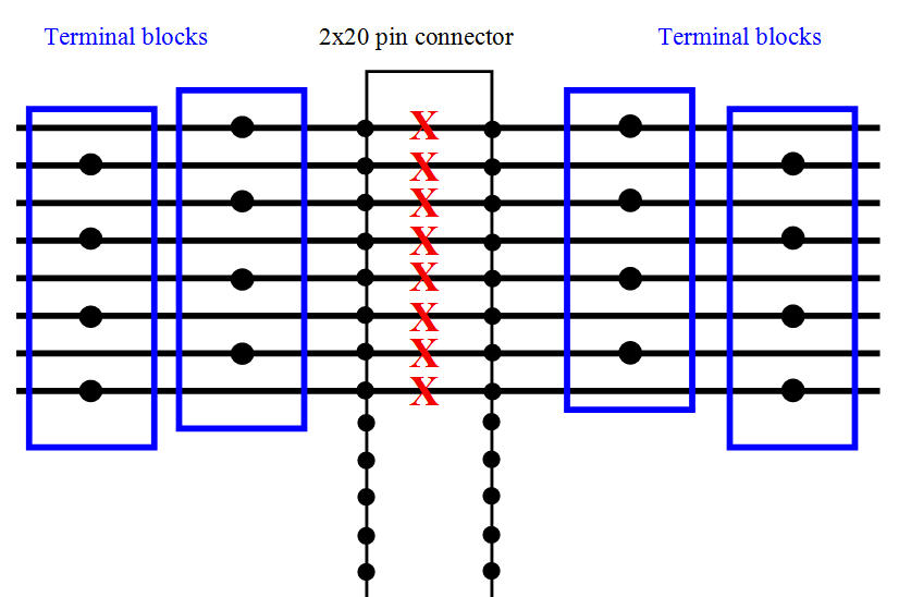
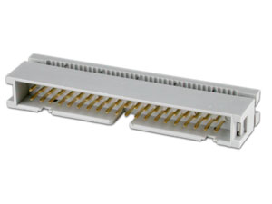
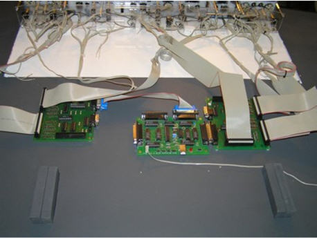
I thought of several ways to do the wiring. 1. Build a simple breakout board using perf board that has strips of lines horizontally. When you put the legs of a 2x20 pin connector, they are too close together and won't match those in terminal blocks that are spaced twice further apart. So use another terminal block moved a hole further down. the first block will line up with the legs of the 2x20 pin connector's odd number legs, while the second block with the even ones. Do so for the left side of the connector. Break the strip on the perf board joining the left and right side of the legs. Repeat the same for right side. See first picture. Even if this work we'd require quite a number of terminal blocks. 2. Use the connector with legs stick out like the above, and use female crimp pins to connector on one side, while the other side is the male pins that will connect to a female connector. see pictures 2 and 3. This way is flexible as there is no soldering and the female crimp pins can be pulled out anytime or swapped. But will need to use shrink tube to keep the crimp pins from touching each other. And assuming the connection with the stick pins is good. 3. Still using an IDC connector but this time not with the straight through legs but the type that will be crimped with a ribbon cable. see picture 4. this is also easy to do but the wires are all joined and can't be swapped. So this way all switches are joined by a ribbon cable to a male IDC, which connects to a femal IDC to anoter ribbon cable to the master card. Easy to seperate from the card. 4. The easiest way is to connect straight from the master cards to the switches. Least work and cost. see picture 5.

-
Sorry I have no clue about MP stuff. Never tried it (don't look at me like that). I am going to be using OC and I believe I can figure out some of the coding. We can definitely exchange notes about OC later when things start rolling. I just installed the beta 2 tonight and noticed that ED has not yet assigned numbers to the devices in devices.lua like what they did in BS. I wonder if we can just assign numbers ourselves to make it work. Also they have not added any key commands to switches. So its lua or nothing right now if you want switches to work. I'd start figuring things out once I get my OC cards. I think OC is a safe choice for I/O given we have veterans here. Other solutions like Hagstrom will be a challenge if ED doesn't add key commands as Hagstrom needs to record key commands to make it work as it's just a keyboard emulator. Same for leo boards. OC's SOIC is proven to work with DCS.
-
Not really. It was taken from TH2G so it's wide screen. It's not meant to be dimensionally proportionate. I just wanted to show Oakes the color of the caution light. Hope this is what he was looking for. Someone else better at drawing than me should prepare the template for the UFC. I will attempt it only later when I am done with my left and right consoles.
-
I've seen his thread before. Very organized, must be thousands of hours given the level of details. Lots of things to learn from him. It looks like he has lots of funds. I just have to do it the much cheaper way.
-
I can't remember how many inputs can one master card take. then multiple that by four for 4 mc to one usb card. we are talking inputs alone. if you plan to build ALL switches in the cockpit, that's a lot of them. you may need more than four. well just go with 4 for now and if you need more get them later with another usb card. there's a lot of toggles, push buttons (CDU, UFC), rockers, rotary switches, encoders, etc. I don't have RJ45 plugs or punchdown blocks lying around. getting many of them will cost quite a bit. I think getting those 40pin ribbon cables will cost a lot less. I'm very tempted to wire directly from the MC to the switches directly and skip the hassle of breakout boards. maybe I'd use HE10 connectors as the in-between.
-
Do you plan to use breakout boards? Or connect the switches directly to the OC cards? it's recomended to seperate them, though I'm tempted to skip this to save cost. You can connect the USB expansion card to the master cards directly to each other or via printer cable. But if you put them horizontally they'd take up a lot of floor space as you'd need several master cards and maybe two or three USB expansion cards. I plan to mount my cards vertically on the 'wall' below my panels and spread the cards out along the length of the left and rigt consoles. I also thought of using UTP and Rj45 jacks but by default the OC cards use the 40 pin connectors which means using break out boards to change to RJ45. Still on the fence about this.
-
Here you go Oakes.
-
I don't know the exact measurement of the AHCP, but it looks the same width as the gear/flap panel and the fuel qty panel. Guess they are all supposed to be the same width? As for the height it looks the same as the temp/rpm gauges panel. These other panels are 'old', there should be a way to find out their dimensions.
-
If you have OC cards then you don't have to wait for the switches to be assigned key commands by ED. Who knows how long that'd take. You can use lua. I saw Oakes' example in a thread. It was quite simple and easy to follow, at least for a toggle switch. The other stuff like pots, encoders, and esp. output stuff I'm sure will be more complicated.