Gremlin77
-
Posts
303 -
Joined
-
Last visited
Content Type
Profiles
Forums
Events
Everything posted by Gremlin77
-
Hey, this is my money I paid with my last taxes...........I'm from Germany, the land with the idiots who keep up the great idea of Euro just kidding...nearly
-
As most of you know, I have my own interface system running with arduinos and the i2c bus. Now, I found a way to make my arduino behave like two joysticks with 144 buttons each. (using MegaJoy, an slightly changed UnoJoy version for the arduino) These I can now use in HELIOS. But I came to a point, I ´don't get any further. What works is, that I can toggle my real switch and the DCS switch toggles too. So the main issue works. But on startup of DCS, the real switches and the DCS switches may have different positions. Then you have to toggle the real switch (witch causes a trigger signal in HELIOS) to synchronize them. For better understanding of my problem a quick example: I have a three position switch (two joystick buttons) connected to the AHCP Panel Master arm switch. Woks fine when you toggle the switch. But starting up DCS, the simulator Master Arm Switch is in the middle "SAFE" position for default. When now my real switch is in e.g."ARM" position on startup, I have the problem, because the simulator switch and real switch don't fit together. When I toggle real switch everything is fine again. So, 'cause I don't want to put every switch in default position before launching DCS, I need a way to synchro the real and simulated switches at startup. Anyone an idea how to do this?
-
okay, then I'm happy that I was lucky that it works like this.....
-
On this cannot give you a quick reply. The SIOC uses UDP, my software also. You'll have to find out on your own, 'cause I sold all my opencockpits stuff, so I'll have no chance to give it a try. Sorry. If you can figure out what format the UDP string has to have, I can modify my program to generate the right string format for ya
-
At the moment I export 4 screen areas with 300x300 pixels every 0.1 Seconds. With this setting it runs very smooth. Every screenarea has compressed about 8 kB in size, makes about 320kB/Second to transfer. For experiment I used the laptop connected via WLAN at medium strength having no problem. In my pit I'll connect via LAN, should be no problem also. Will have to check what happens when the HELIOS data UDP stream also runs. I am a bit surprised, that the whole copy from screen, compress and transfer process doesn't affect DCS framerate at all. Seems that the whole process needs only very few CPU power. Don't know if it is usable for players who play in multiplayer mode. Think, there could be problems with network traffic then.
-
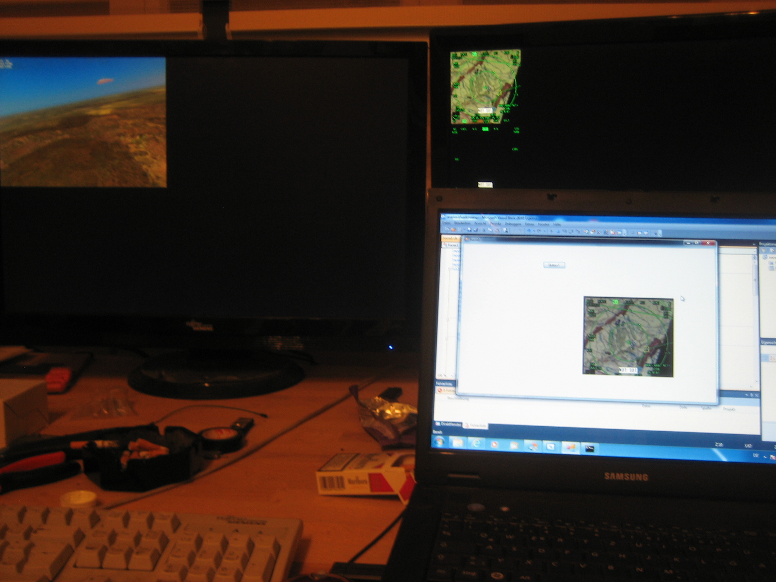
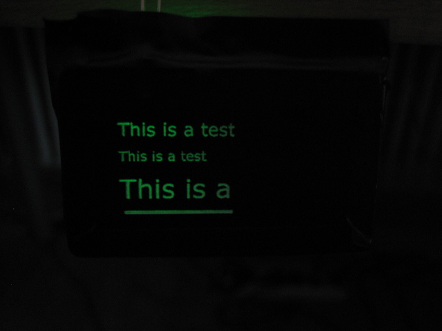
okay, did some programming last night..... And what we have here: a nice little program that sends a monitor snippet over the network to another PC. Why did I write that program? Because I f... of with having only one PC for all my MFD's HUD etc. Now I am able to use all my Lilliput monitors on a second PC and send the desired Screenparts to the displays. In the pic below you can see A-10 running on the two big screen just for trying. The MFD's are exported through monitor configuration on the right screen. From here they are copied over UDP to the small laptop in the front and displayed on screen. Now I can finally run HELIOS and the rwr, MFD's and CDU on a dedicated PC Halleluja!!!!!:lol::lol::lol::lol: And the best thing: No fps drop due of program running in background If there is interest, I'll pimp the prog the next days, so you can adjust which screenparts you want to copy where on the client PC screen more convinient. Now, you have to write it "in-code"

-
I always thoght that the use of CrossFire is done via graphics drivers Catalyst. This should not depend on game. But perhaps I'm wrong. The only thing I can say is, that I had about 80-90 fps with CrossFire, two Lilliputs and two beamers and only about 33-40 fps without CrossFire, one beamer and three Lilliputs. So I thought the loss of about 50% couldn't come from the one more USB monitor, 'cause overall resolution is less. I will try to take out one graphic card, because DisplayLink doesn't support multiple graphic cards. Perhaps because of this the loss is so extreme.
-
Start from the beginning.....................making panels
-
due to loss of CrossFire. Okay, running at full details and 1880x1800 pixels. But I think will get problems in future when I use the three projectors. Then resolution is at 4440x1800. Maybe I'll have to change graphic card then...
-
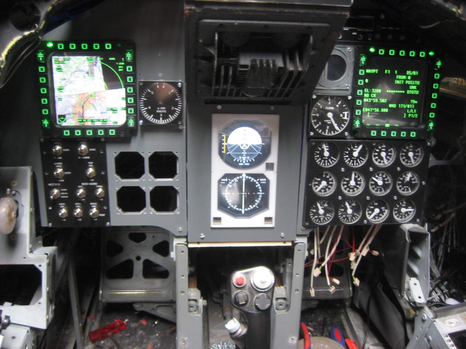
Found out that DisplayLink doesn't work together with CrossFire........who should know that????? Disabled Corssfire, all monitors work.....and fps go down to 40, f... Here's a quick pic of running displays
-
today I started to connect the USB devices like monitors stick throttle and mfd. For getting things to work while constructing the floor, decided to just install a rear projection plate that can be easily removed while woodwork. With the Lilliput USB monitors I have some problems. Perhaps someone can help. I have three lilliput USB monitors. when I connect two, everything works fine. But when I connect the third, displaylink software runs crazy not recognizing any monitor at all and flickering main monitor on and off every few seconds.(You see the displaylink software start and end a recognition try every flicker) It's not a monitor problem, because it doesn't matter if I connect the two MFD monitors or one MFD and the ADI monitor. With two it always works. Only the third makes problems. Downloaded latest displaylink drivers with no effect. Any ideas?
-
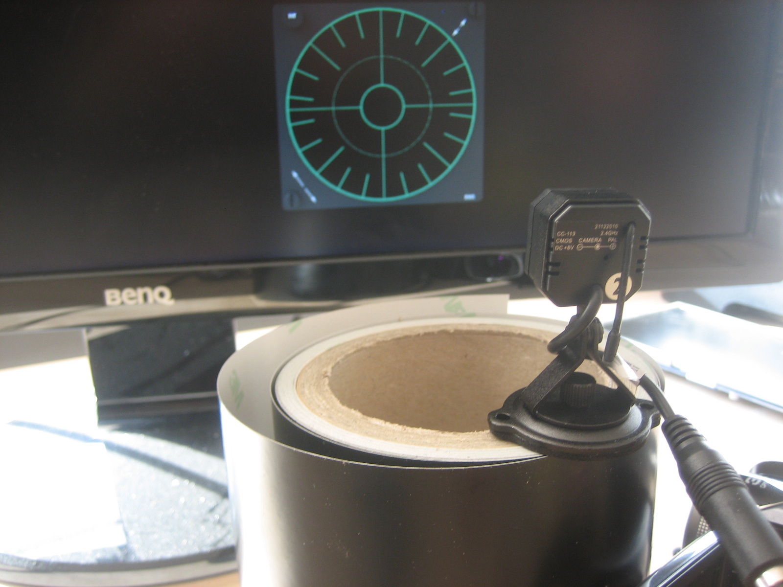
Okay, bought a "wireless spy-cam" from the store for 28€. Here is the result: (In reality you can't see the pixels like in the pic) The camera looks like this: The result is let me say okay for rwr. But if you try it out with e.g. Backup ADI the quality is too poor for a good reading. For my RWR I'll use it as "cheap solution for future improvement"
-
I use extruded acrylic. What in your oppinion is the advantage of cast acrylic? It's more expensive, this I know. And less brittle.
-
My plastics have no paper on. They have only a foil on top and bottom side. This I have to wrap off, cause it melts.
-
I realized it his way: You push your real button -> Send the 1.0 (or is it 0.1? don't remember...) You release your real butoon -> Send the 0.0 This way you keep the repeating funtionality of the ingame CDU (if it has one...) If you come to the problem with repeating letters, just programm a short trigger, that send changing values.
-
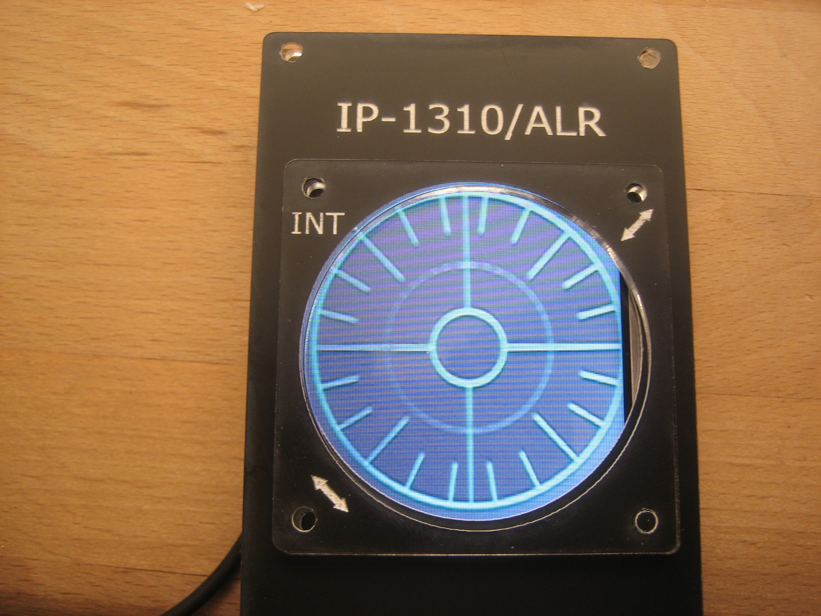
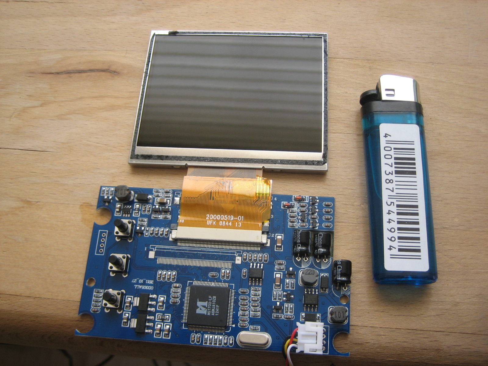
For the RWR screen I bought this little screen for 20 € at ebay. This device is originally a screen for a car backview camera. I screwed it down and now I have a nice little screen for RWR with 3,5'' for a good price. Now comes the hard part: It has only a composite input, so you'll need an converter from VGA to TV signal, and that is quite expensive. Having a screen attached to PC which I use to output all the possible instruments like MFD, HUD etc, I'll try to get a little spy - cam (about 8€) to "film" the RWR from the monitor and send it via chinch cable to the TFT. Hope quality loss will not be so extreme. If this works, I'll do the same for 2nd ADI, clock etc. without wasting an additional VGA output.
-
yes, be warned! this hobby can lead to total desaster!!!!! Just look at me, my daughter will kill me, when she's old enough to realise that there could have been a swimming pool in the house......and now there stands Dadys old ugly plane....Beware me of that day!!! BTW I used an 42'' TV behind the front panel. It was I think a bit too big. Think better and cheaper way is to use two 17'' Monitors. Better resolution and flexible in positioning. Look at the forum, have in mind there is a CAD drawing of the real A-10 Frontpanel with dimensions.
-
The guys are right. Just start at one point and go one step after the other. I suggest that you take a plate of wood, drill some round holes with a forstner driller and screw this on a monitor. Using the brilliant software HELIOS you will quickly get some moving gauges. Believe me, this will motivate you to go on. If you look at the first pages of my building thread, you can see I also started form that point. Then just figure out what interface works best for you. Try for beginning to find one you can use directly in helios (something that imitates joystick button) So, just start up and have fun.
-
The rudders look rusty, but they work smooth. Just have to think about getting the signal to the PC. On the rudders an hydraulic cylinder is attached, perhaps I'll take a pressure sensor to create a signal. Don't know yet. Will be a long ride, 1200km, but you're welcome!
-
you're right! And I thought my beamers are too dark..... :-)
-
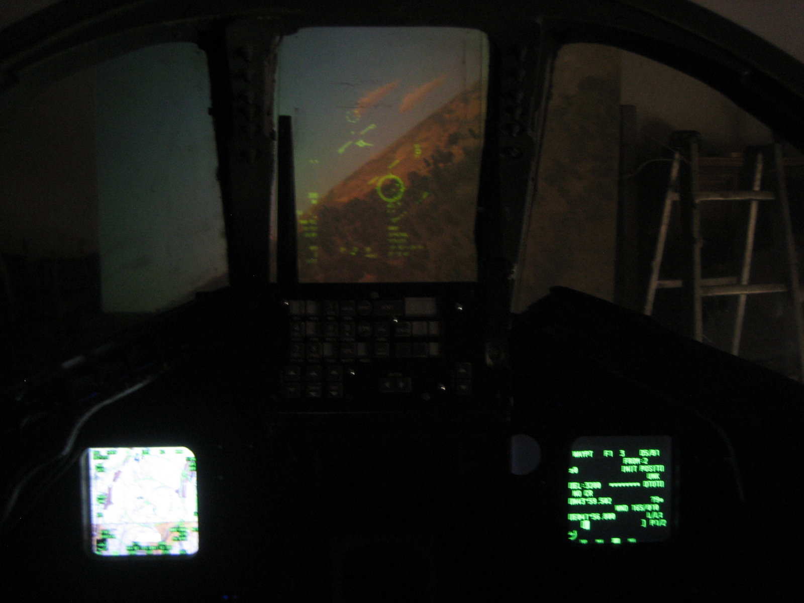
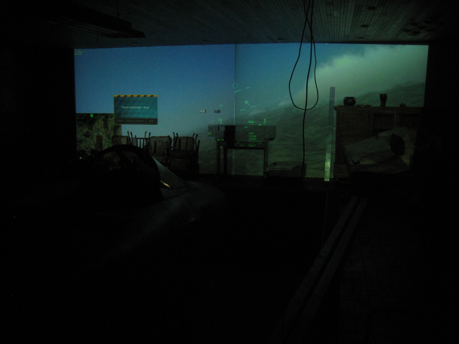
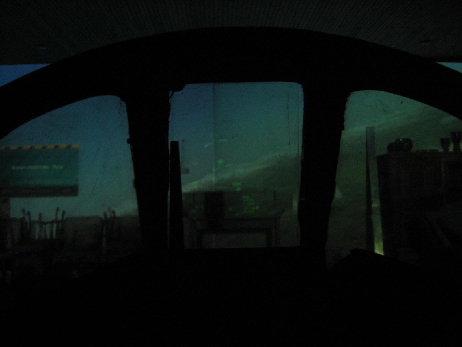
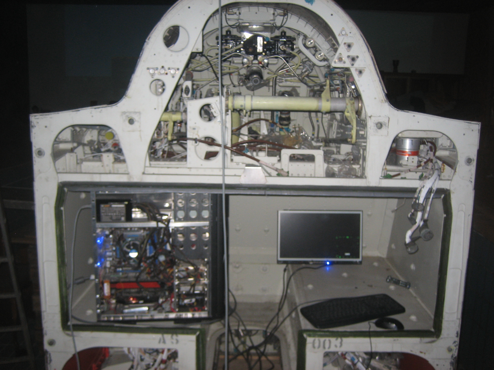
Just had to try it out....couldn't resist.... Have to forget about furniture in sight.....and the bad photo quality, in real looks great! and "inside cockpit view" Thought about installing a real working HUD, but the illusion is so good, I'll forget about that. PC installed tentative in the back of fuselage. Connected the two graphic cards via SLI running for 3x1280x800 at about 80 fps. (the last 1280x800 is the PC screen, will be also a projector in future when I installed the 7 Meter curved screen) Just will throw in stick and seat and here we go!
-
Looking awesome! What interface are you going to use?
-
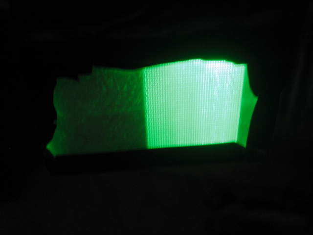
Here are nearly night results with only one LED Sorry for bad camera, look better real life....
-
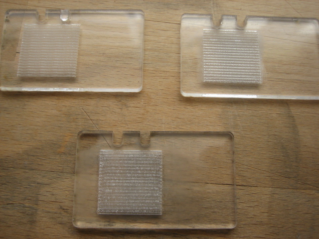
Tried several Patterns with different depths and what should I say? Works phantastic. Will send "Night pictures" later, cause I cannot darken my electronics room. Damn, you saved my life, 'cause I thought I have to redo all my panels which have no backlight. Now I just will engrave a litte pattern to it. Think we should try what happens when you just sand the acrylic with a 100 corn. Perhaps this will work too. There are no real differences if the engraving is deep or only on top. Here are the trials:
-
Will try this doing a piece of acrylic with some different patterns. Will look, what works best. Very nice idea, thank you!