
The_Fragger
-
Posts
907 -
Joined
-
Last visited
-
Days Won
5
Content Type
Profiles
Forums
Events
Everything posted by The_Fragger
-
Really appreciate it! After all these years, it became clear: we’re either doing it right – or not at all. The BO-105 isn’t just about flying, it’s about feeling real. And that’s exactly what we’re still refining
- 1541 replies
-
- 15
-

-
UPDATE – BO-105 DEVELOPMENT STATUS It’s time for a proper update. Since 2013, I’ve been working to bring the BO-105 into DCS – and the path has been anything but smooth. I’ve gone through technical hell, complete rewrites, system redesigns, hardware issues – and just as many challenges caused by people, not technology. To be clear: some individuals actively made it difficult to realize this module. Instead of support, I encountered deliberate resistance, withheld knowledge, and ego games from so-called “experts” who could’ve helped but chose not to. But I didn’t give up. I pushed forward. A true game-changer came with access to the original technical documentation from Lager Lechfeld. These documents didn’t just clarify the system architecture – they provided every single value needed to accurately simulate the engine: flow rates, pressures, temperature limits, control curves, response timings – all of it. That level of data brought the entire project to the next level of fidelity. Right now, we’re fully focused on improving and finalizing the fuel control system, which is directly dependent on the GPFC (Gas Producer Fuel Control) – the brain of the BO-105’s turbine management. The current implementation includes: – Fuel flow logic and pressure dynamics – Ohmic resistance, voltage, amperage, and current load behavior – Hydraulic system response and complete onboard electrical logic – All connected in one integrated simulation environment The engine is being simulated 1:1, using real-world parameters – no assumptions, no placeholders. Just raw, system-level fidelity. And that’s not all – the entire rotor system is fully modeled, including the hingeless, rigid rotor head and its unique 78° phase lag. This key difference to conventional rotor systems has a significant impact on control behavior and is being replicated exactly in the flight model. So why all this? Because the BO-105 is the love of my life. This isn’t just about “getting it to fly” – it’s about honoring a machine that deserves to exist in DCS in all its technical brilliance. To those who’ve supported this project over the years – thank you. To those who made it harder – congratulations. You made it take longer. But you didn’t stop it. This isn’t just a helicopter mod. It’s a mission that started in 2013 – sharpened by adversity, fueled by obsession, and built with absolute love and respect for this aircraft. And yes – I know the flight model commentary is coming. I’ll be reading it… popcorn in hand
- 1541 replies
-
- 37
-
-

-
[UPDATE – ENTWICKLUNGSSTAND DER BO-105] Es ist an der Zeit für ein richtiges Update. Seit 2013 arbeite ich daran, die BO-105 in DCS zum Leben zu erwecken – und der Weg dorthin war alles andere als einfach. Ich bin durch die technische Hölle gegangen: komplette Neuprogrammierungen, System-Redesigns, Hardwareprobleme – und mindestens ebenso viele Herausforderungen, die nicht durch Technik, sondern durch Menschen verursacht wurden. Um es klar zu sagen: Es gab Personen, die aktiv daran gearbeitet haben, dieses Modul zu verhindern. Statt Unterstützung gab es bewusste Blockade, zurückgehaltenes Wissen und Egotrips von sogenannten „Experten“, die helfen konnten, aber sich entschieden, es nicht zu tun. Aber ich habe nicht aufgegeben. Ich bin weitergegangen. Ein echter Wendepunkt war der Zugriff auf die originale technische Dokumentation aus Lager Lechfeld. Diese Unterlagen haben nicht nur die Systemarchitektur bestätigt – sie lieferten jeden einzelnen Wert, der notwendig ist, um das Triebwerk exakt zu simulieren: Durchflussmengen, Drücke, Temperaturgrenzen, Regelkurven, Reaktionszeiten – alles. Diese Detailtiefe hat das gesamte Projekt auf ein neues Niveau gehoben. Derzeit liegt der volle Fokus auf der Verbesserung und Finalisierung des Fuel Control Systems, das direkt mit dem GPFC (Gas Producer Fuel Control) verknüpft ist – dem Herzstück der Triebwerksregelung der BO-105. Die aktuelle Implementierung umfasst: – Logik des Kraftstoffflusses und das Verhalten der Druckdynamik – Ohmsche Widerstände, Spannungs-, Stromstärken- und Lastverhalten – Reaktionslogik des Hydrauliksystems sowie das komplette Bordstromsystem – Alles eingebettet in eine integrierte Simulationsumgebung Das Triebwerk wird 1:1 simuliert – basierend auf realen Parametern. Keine Annahmen, keine Platzhalter – sondern rohe, systemgenaue Simulation. Und das ist noch nicht alles: Auch das gesamte Rotorsystem wird vollständig modelliert, inklusive des gelenklosen, starren Rotorkopfes mit seiner charakteristischen Phasenverschiebung von 78°. Dieser fundamentale Unterschied zu herkömmlichen Rotorsystemen hat einen massiven Einfluss auf das Steuerverhalten – und wird im Flugmodell exakt so abgebildet. Warum dieser Aufwand? Weil die BO-105 die Liebe meines Lebens ist. Es geht nicht einfach nur darum, dass sie „fliegt“ – es geht darum, einer Maschine gerecht zu werden, die es verdient, in DCS in all ihrer technischen Brillanz zu existieren. An alle, die dieses Projekt über die Jahre unterstützt haben – vielen Dank. An die, die es erschwert haben – Glückwunsch. Ihr habt es verzögert. Aber ihr habt es nicht aufgehalten. Das hier ist kein Helikopter-Mod. Das ist eine Mission, die 2013 begann – geschärft durch Widerstände, angetrieben durch Besessenheit und gebaut mit absoluter Liebe und tiefem Respekt für dieses Luftfahrzeug. Und ja – ich weiß, dass die ersten Kommentare zum Flight Model nicht lange auf sich warten lassen. Ich werde sie alle lesen... mit Popcorn.
- 751 replies
-
- 22
-
-
-
nullBianka got her helmet

- 1541 replies
-
- 10
-
-

DCS: BO-105 3D/FM Announcement and Discussions
The_Fragger replied to The_Fragger's topic in BO-105 PAH1A1
BO-105 - DE-ICING The Critical Role of Air Intake Anti-Icing Systems in Turbine Engine Performance The air intake system is a fundamental component of any turbine engine, directly influencing engine performance, efficiency, and safety. Under specific meteorological conditions, ice accretion within the air intake can significantly restrict airflow, posing a severe risk to engine operation. A pertinent example is the Allison 250 turboshaft engine, which features an air intake diameter of merely 10 cm—small enough to be obstructed by something as trivial as a compacted snowball. Ice accumulation reduces the mass flow rate of air to the compressor, potentially leading to compressor stall or, in extreme cases, complete engine flameout. Mechanisms of Ice Formation in Air Intakes Contrary to common assumptions, ice can form within the air intake even when ambient temperatures are above freezing. This phenomenon is primarily driven by the thermodynamic effects of pressure and temperature changes within the intake system. The air intake does more than channel ambient air toward the compressor; the compressor actively induces a pressure drop in the intake, resulting in adiabatic cooling. For instance, if the ambient atmospheric pressure is standard (1013 hPa), the induced pressure within the air intake may decrease to approximately 960 hPa due to compressor suction. This pressure drop leads to a corresponding temperature decrease of around 3°C. Consequently, ambient air at 2°C can cool to -1°C within the intake duct. Additionally, the rapid reduction in pressure causes moisture in the incoming air to condense into microdroplets. Upon contact with the sub-zero inner surfaces of the air intake, these droplets freeze, leading to ice accretion. This process mirrors the sublimation of water vapor into frost on cold surfaces, a phenomenon observable on frosted windows during winter. Design and Functionality of Air Intake Anti-Icing Systems To mitigate the risk of ice formation, turbine engines are equipped with sophisticated anti-icing systems that maintain the air intake's internal surfaces above freezing temperatures. These systems typically utilize bleed air extracted from intermediate stages of the compressor. After ambient air enters the intake, it undergoes compression to pressures reaching approximately 6500 hPa, with corresponding temperature increases to around 250°C by the fifth stage of the compressor. At this stage, a pilot-controlled bleed valve allows a portion of this high-temperature, high-pressure air to be diverted and routed to the air intake’s outer skin. The hot bleed air heats the intake structure, thereby preventing moisture from condensing and freezing on the internal surfaces. Operational Implications and Performance Trade-Offs While bleed air anti-icing systems are effective in preventing ice formation, their use introduces certain operational trade-offs. Diverting bleed air from the compressor reduces the mass airflow available to the combustion chamber, impacting both the combustion efficiency and overall engine performance. This reduction necessitates an increase in fuel flow to maintain the required turbine inlet temperatures (TIT), which, in turn, affects the engine's specific fuel consumption (SFC). Moreover, during engine start-up—particularly under cold-soak conditions—activating the anti-icing system can prolong the time required to achieve the kerosene flash point of approximately 48°C in the combustion chamber. This extended start-up cycle increases the electrical load on the aircraft’s battery system, potentially limiting the number of available start attempts in battery-dependent start configurations. Additionally, bleed air is frequently utilized for environmental control systems (ECS), including cabin pressurization and heating. The concurrent demand for bleed air in both anti-icing and ECS functions can further diminish available engine power, particularly in high-demand flight phases such as takeoff and climb. Conclusion The air intake anti-icing system should be engaged whenever the outside air temperature drops below +2°C, as these conditions are conducive to ice formation. Such temperatures are commonly encountered both on the ground during the autumn and winter seasons and at altitude when traversing the freezing level during ascent. However, it is imperative for flight crews to consider the operational penalties associated with anti-icing system activation, including increased fuel consumption, reduced engine performance, and potential impacts on aircraft range, service ceiling, and payload capacity. Efficient management of the anti-icing system, in accordance with the aircraft’s operating manual and prevailing atmospheric conditions, is essential to ensuring both flight safety and optimal engine performance. Simulation Accuracy with MEDUSA The programming with MEDUSA will simulate these processes with a high degree of realism, accurately reflecting real-world engine behavior and the operational dynamics of the anti-icing system.- 13 replies
-
- 19
-
-
-
DCS: BO-105 3D/FM Announcement and Discussions
The_Fragger replied to The_Fragger's topic in BO-105 PAH1A1
3 Guys. -
nullAnimationen vom Aussenmodel: Deails : Augen und Kieferanimationen funktionieren wie erwartet. Vorausichtliches Release der BO-105 ist 2025 ! null 3dsmax_vf4VhZaFav.mp4
-
External Model Crew animation (added eye movement): Everything is working as excepted: null 3dsmax_vf4VhZaFav.mp4
- 1541 replies
-
- 11
-
-
Yeah. But be sure that we are heading for a release in 2025
- 1541 replies
-
- 26
-
-
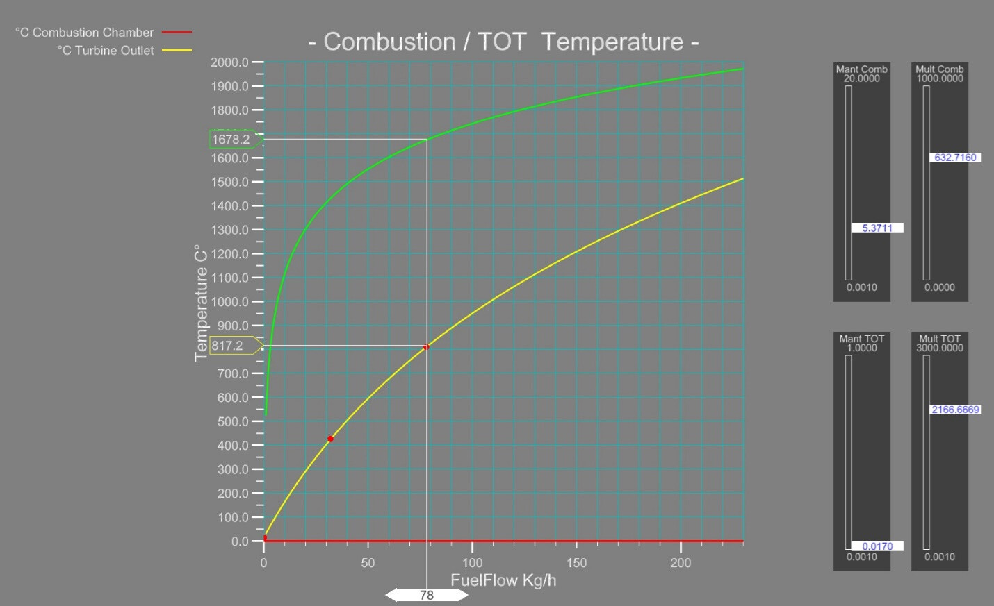
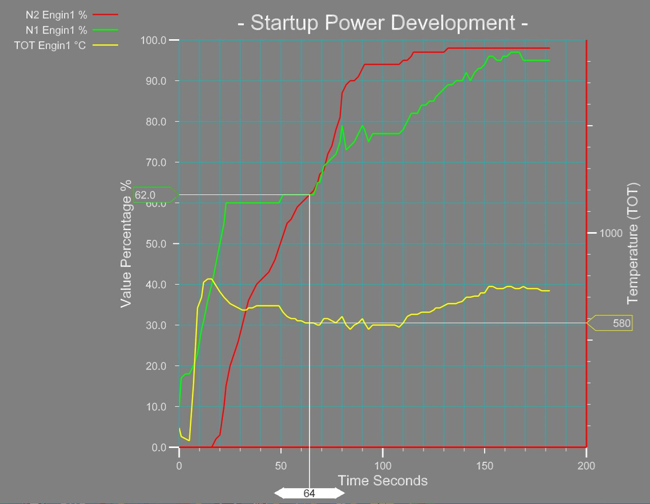
The following images demonstrate how we calculate engine behavior in a simulation. The first step is to assemble physical graphs, which reflect the parameter development under different conditions. For example, the temperature development in the combustion chamber and the turbine outlet on base of available fuel, oxygen, temperature and pressure arriving from the compressor: The next step will be a test with our jet engine test application: The image above shows a situation during startup, while the engine is driven by the starter generator. It can easily be seen that the compressor temperature of 107.2 °C is too high for the observed N1 RPM at 10%. It needs to be adjusted to approximately 50 °C, which is close to the kerosine flashpoint. The jet engine test application allows us to calibrate all graphs online to see the results in the gauge displays. The behavior is always compared to the official documents and to real time diagrams recorded during real flights. The image below shows a real startup of the BO-105 left engine Allison 250-C20B. This method results in real-world behavior during a simulation. The functions are coded with the MEDUSA multitask system, which was developed especially for flight simulations. To make the article clearer: The first image, showing the combustion and outlet temperature, is one single example of how the development of physical values is managed. This is done for all parts of the engine. The second image shows our test environment for jet engines. The gauges show the current condition of the compressor, Combustion Chamber,N1and N2 with temperature, pressure, and air speed. The bleed air valve condition is shown in the N1 RPM% gauge. There are two movable marks on the scale. The green mark is the RPM% border for a fully open bleed air valve. Values above the red RPM% border cause a fully closed bleed air valve. The position of the marks is movable depending on the outside air temperature. Even the combustion chamber internals are shown in temperature and air speed. The next stage is the N1 turbine fan driven by the expanded air mass and speed. The N1 turbine fan is fixed to the compressor shaft. So, the N1 RPM% gauge also shows the condition of the N1 turbine fan. Behind the N1 turbine fan, the N2 turbine fan receives the airstream, which is slightly degraded in speed, temperature, and pressure. This is displayed as N2 RPM% and torque. In addition, the N2 torque is transferred to the engine gearbox. The output shaft torque of the gearbox is shown in the same column. Finally, the forces impacting the rotor shaft are displayed. The entire calculation could be simplified to one formula with the disadvantage that a partial malfunction of a single engine and its result chain would not be noticed. Therefore, we go as deep as possible into the physical rules of every single part of the engine. The engine condition, shown with the gauges in the second image, is not finally tuned. As you have noticed, there is a discrepancy between compressor RPM, pressure, and temperature which needs to be calibrated. Here we can play with the compressor blades surface area, its lift coefficient and the air duct area. At that point, we are at the limitations of physical calculations. We cannot include the effects of blade vortexes, curves in airducts and specific lift coefficients. We calculate with straight values and following the graphs based on special formulas. We adjust the values to come to the same results as in the real world. This is even the reason that it takes that time to finalize the project. The third diagram image does not display a simulation session. It shows the startup of the left engine of a real BO-105. The values are taken from the cockpit instruments. Since there are no engine air pressure gauges available in the cockpit, we were limited to what could be seen in the cockpit. The fluctuations of the graph lines were mostly caused by the pilot, who did not move the throttles with one smooth speed.
- 1541 replies
-
- 10
-
-
-
Soon. But first we need to figure out how to get the sounds working in DCS.
-
Yes !
-
3dsmax_xGUcDKRhya.mp4 Multiple animations on one mesh ...and it works inside DCS
- 1541 replies
-
- 11
-
-
It is sound only for the moment.
-
IN_TheStreamRun_Bo105_(F10N)(StartUpFlyBy)_2020-04_08.mp4 BO-105 Titelsong. Ingo Nasse hat da echst was wundebares gezaubert
- 751 replies
-
- 13
-
-
IN_TheStreamRun_Bo105_(F10N)(StartUpFlyBy)_2020-04_08.mp4 BO-105 Theme by Ingo Nasse
- 1541 replies
-
- 14
-
-
-
MEDUSA ENGINE (DCS: BO-105) The BO-105 has two engines of type Allison 250-C20. The engines drive different devices in the helicopter, starting with the rotor system down to the heating system. The difficulties in the simulation are the endless number of physical parameters influencing the behavior and efficiency of the engines. In a simple software solution, all the possible parameter situations are solved in an IF, THEN, ELSE solution. This cannot cover all possible parameter combinations and normally it results in imprecise and unexpected situations. The use of the MEDUSA software system offers a smart possibility to simulate such a system close to natural behavior. In MEDUSA, all different parts of the engine are divided into autarkic tasks. Every task calculates its function along physical graphs and makes the result available to all neighboring tasks of the engine. The Gas Generator in our simulation is divided into the following tasks: MEDUSA Engine Control Task Engine Control observes the Pilot’s Control Handle, which defines the intended percentage of the engine power. To maintain the intended engine power, the power control circuit controls the fuel injection into the combustion chamber and, if necessary, the use of the air bleed valves at the compressor stage. MEDUSA N1 Compressor Task The compressor stage consists of six axial and one radial blade elements. It compresses the air in a ratio of 6.2:1.0. The air temperature, pressure, and density increase depend on the compressor’s rounds per minute (RPM). In the simulation, both values are calculated exactly along their physical graphs, including the mass acceleration and drag of the spinning compressor. During engine spooling, the compressor is driven by an electrical generator. As soon as the compressor RPM reaches the kerosene flashpoint temperature, the combustion in the combustion chamber is ignited. The compressor is then driven by the N1 Van hot air stream. MEDUSDA Combustion Chamber Task The combustion chamber receives the compressed air stream from the compressor. In the simulation, the correct flame parameters for the kerosene amount and burner temperature are calculated. Here, the amount of available oxygen and the temperature from the previous calculation loop are taken to calculate the final percentage of burning fuel. This determines the air gas expansion, causing a hot air stream to leave the combustion chamber. While the hot air stream passes the N1 and N2 sections, it cools down to reach a temperature measured in the turbine outlet. This temperature is shown in the cockpit to monitor for exceptionally hot or cool turbine outlet temperatures (TOT). MEDUSA N1 Van Task The N1 Van is the first station reached by the hot airstream. The Van is mechanically connected to the compressor. It is driven by the hot air stream and produces torque to drive the compressor. This takes about 55% of the energy generated in the combustion chamber. The simulation calculates the torque by the speed of air and the air density. MEDUSA N2 Van Task Behind the N1 Van, the N2 Van is installed. The N2 Van has a mechanical connection to the gearbox, driving the rotor via a transmission, constructed as a freewheel system. This ensures that the rotor system may have a higher RPM than the RPM produced by N2. The freewheel is important for an autorotation procedure. The N2 Van uses the remaining 45% of the hot air stream to calculate torque to drive the rotor via the gearbox. Even here, the simulation calculates the torque by the speed of air and the air density. All tasks are influenced by the ambient parameters of outside air temperature and outside air density. Both parameters depend on the current geometric altitude. The advantage of the MEDUSA system is, that the result is produced automatically. Thus, the maximum performances, like maximum altitude with different loads and changing ambient parameters, are presented as in the real world. The only exceptions are the load-bearing capacities of mechanics and materials. Here, the fixed limits from the documentations are used in the calculation. Conclusion Every device in the helicopter, like engines, generators, … runs its own MEDUSA thread. A MEDUSA thread executes a list of tasks as described above for a Gas Generator. The advantages are: The advantageous use of multiple kernels in a computer system. Easy to understand software organization. Encapsulated and autarkic software snippets. Simplified software changes without side effects. (With the exception of effects, which would happen in the real world). null
- 1541 replies
-
- 16
-
-
Ich lieb diesen Film
-
Missile Rag with additional Dampers:
-
null null
- 751 replies
-
- 12
-
-
-
Servus Simmers, HOT MUNITION ! YES ! ...genau darum haben wir uns gekümmert und möchten Euch heute den Fortschritt des neuen statischen Objektes zeigen. Das Bild zeigt eine Palette mit gestapelten HOT-Raketen für das neue DCS-Cargo-System, um die Versorgung der BO-105 mit der CH-47F sicherzustellen. Wir sind auch ziemlich zuversichtlich, dass wir in den nächsten Wochen den ersten Flug der BO-105 mit dem neuen Flugmodell präsentieren können. Die Screens zeigen den Weg zu DCS (6 Stunden Arbeit).
- 751 replies
-
- 10
-
-
We have taken care of the ammo supplies and would like to show you the progress of our new static objects today. The picture shows a pallet of HOT missiles for the new DCS Cargo System to ensure the supply for the BO-105 with the CH-47F. We are also confident that we will be able to present you the first BO-105 flight with the new flight model in the next few weeks.
- 1541 replies
-
- 15
-
-
-
yes
-
Our pilot BIANKA has successfully passed the final exam to become a pilot of the BO-105.
- 1541 replies
-
- 26
-
-
-
Her Name is BIANKA Welcome BIANKA. She refects 11 Years of BO-105 development.