atorque
-
Posts
74 -
Joined
-
Last visited
-
Days Won
1
-
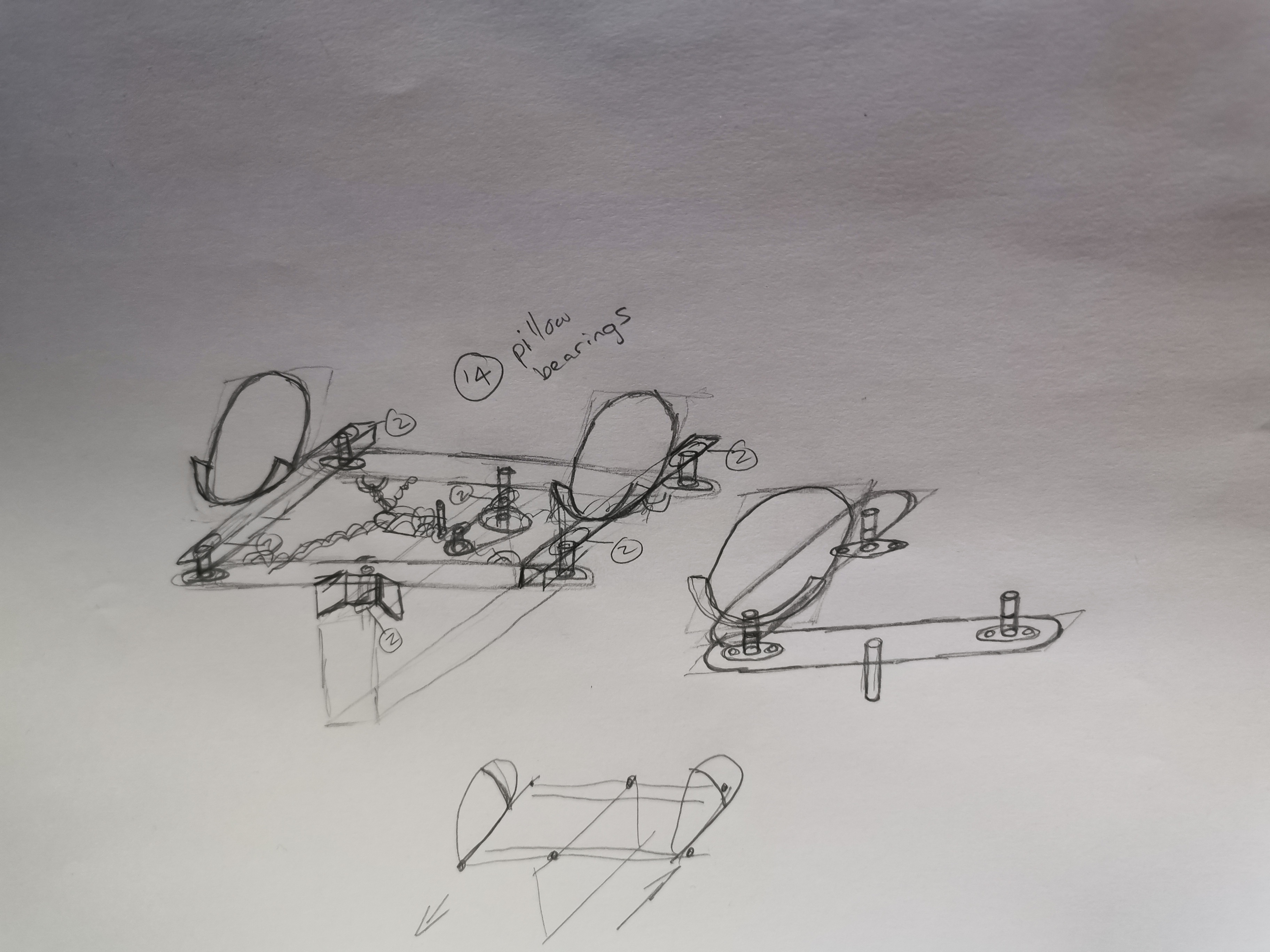
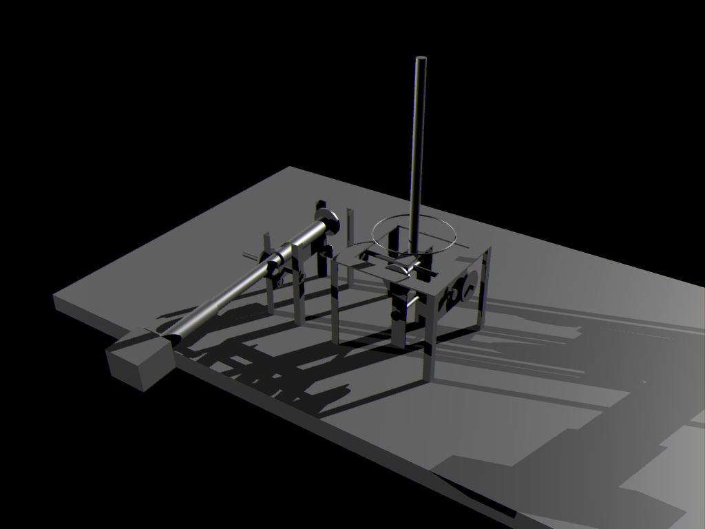
this is my version of making plans, i sketch something, i test it in some 3d software and then i get my grinder and welding machine and go to town

-
Sorry mate, I am not using any blueprints because that would limit what I can use. Here is an example. Lets say the blueprint calls for a tube with a certain outer and inner diameter. Now I have to find suitable material, and find a lathe big enough to accompany a mandrill. I have the skills but not the equipment. I decided to just cobble it together as best I can because I do not see me having access to mills and lathes any time soon. Those days are behind me. I use what I can find laying around, or beg, borrow, steal. Next I try to find hardware that is cheap but reliable. For example the pillow bearing I use. I decided to build the physical axis out of 8mm stainless rod and 8mm pillow bearings because the bearings are cheap as chips. I have used 12 bearings so far, and I used two pin roller bearings inside the shaft of the cyclic to make the throttle rotate. I will use another 14 bearings just for the pedals I am making. My point being if I had to purchase a specific size of bearing or material because a blueprint said so, then I am limited to the hardware I can find, and I am forced to pay the whatever it costs. The way I am doing it currently is to try and find some middle ground. My end goal is to make something that works reliably, and for a long time. I am currently experimenting with my axis and getting everything wired together. I started with the switches and buttons, and now I moved on to experimenting with my axis. I am still waiting for the hall sensors to be delivered, but once they are, I can begin playing with that. I have a whole box of potentiometers but I will first try and make the hall effect sensors work on my main axis and if that fails completely, then maybe I will use pots. You will also notice I am not using any cams or springs because I am not a big fan of things that wear out that quickly. I am trying to use gravity to return my axis, I doubt it will work but I have to try. I am building the peripherals that I want, but with junk. All of my axis are 30 degrees movement apart from throttle. The throttle already rotates 90 degrees which feels quite close to the machines I have flown in real life. The rest of the axis are being translated to 90 degrees using CNC drive parts. The reason I chose this is because the parts are very affordable, and they work without wear or slack unlike cut gears. This again was a big experiment on my part but it seems to be working quite well. I expected to have to add tensioner pulleys but I have not needed any yet. So gravity gives my collective a feeling of being free, but not feather light. There is no resistance but there is weight. I hope that makes sense. I expected my gearing to add some friction but I have detected none. The gearing system is however detecting all movement, so the belt worked out better than I expected. My button selection and layout is entirely my own choosing. I simply add the stuff I want instead of trying to build a specific cyclic or collective. As for your question about making it accurate, there are always helicopter museums, which usually do not get visitation much. If you call ahead and speak to the guy running the museum, you can sit in a cockpit, and take some measurements and photos for yourself. This would be the easiest way to get data. The guy might even have some books you can page through and take photos. That part is easy mate. The hard part is actually building it. Here is what I mean. If the Huey has a specific range of movement, you then have to take that movement and somehow bring it into the digital world. Lets say you have a potentiometer that moves 360 degrees, and lets say the collective in the huey moves 40 degrees for example, you now have to translate 40 degrees into 360 degrees somehow. So you have to make a gearbox of some kind which will require very specific cut gears. Unless you have a lathe and you know how to cut gears, you might find it difficult to source the exact gears, with the exact shaft sizes, but not impossible. I want a movement that is comfortable. From my testing that is 15 degrees in either direction for a total of 30. That seems to work for the cyclic and pedals also. So I decided to stick with that number. I looked at all the gears I could find that are belt driven, because my experience with gearboxes leaves a bad taste. The best I could do was 1:3 so thats what I went with. The reason I am translating at all is because 30 degrees is a very small range to to divide into 4096 steps. I hope 90 degrees will be enough to accomplish what I want. Since each degree has more than 45 steps, I might still be overly sensitive but more experimentation is required. If you want, I will let you know how it goes.
-
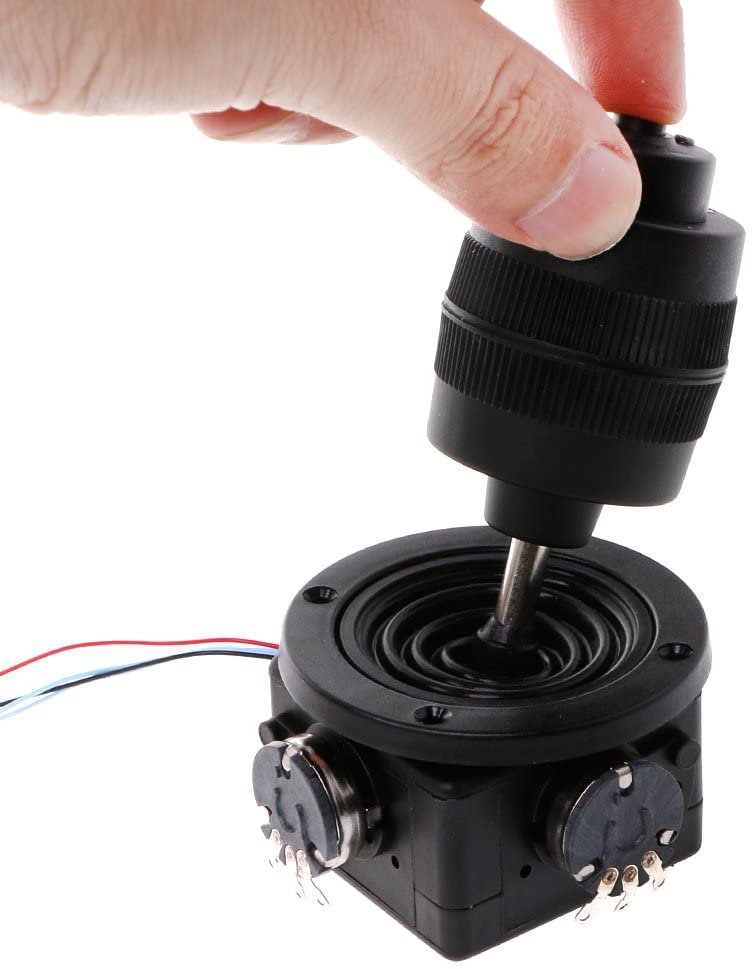
I might experiment with one of these for kicks
-
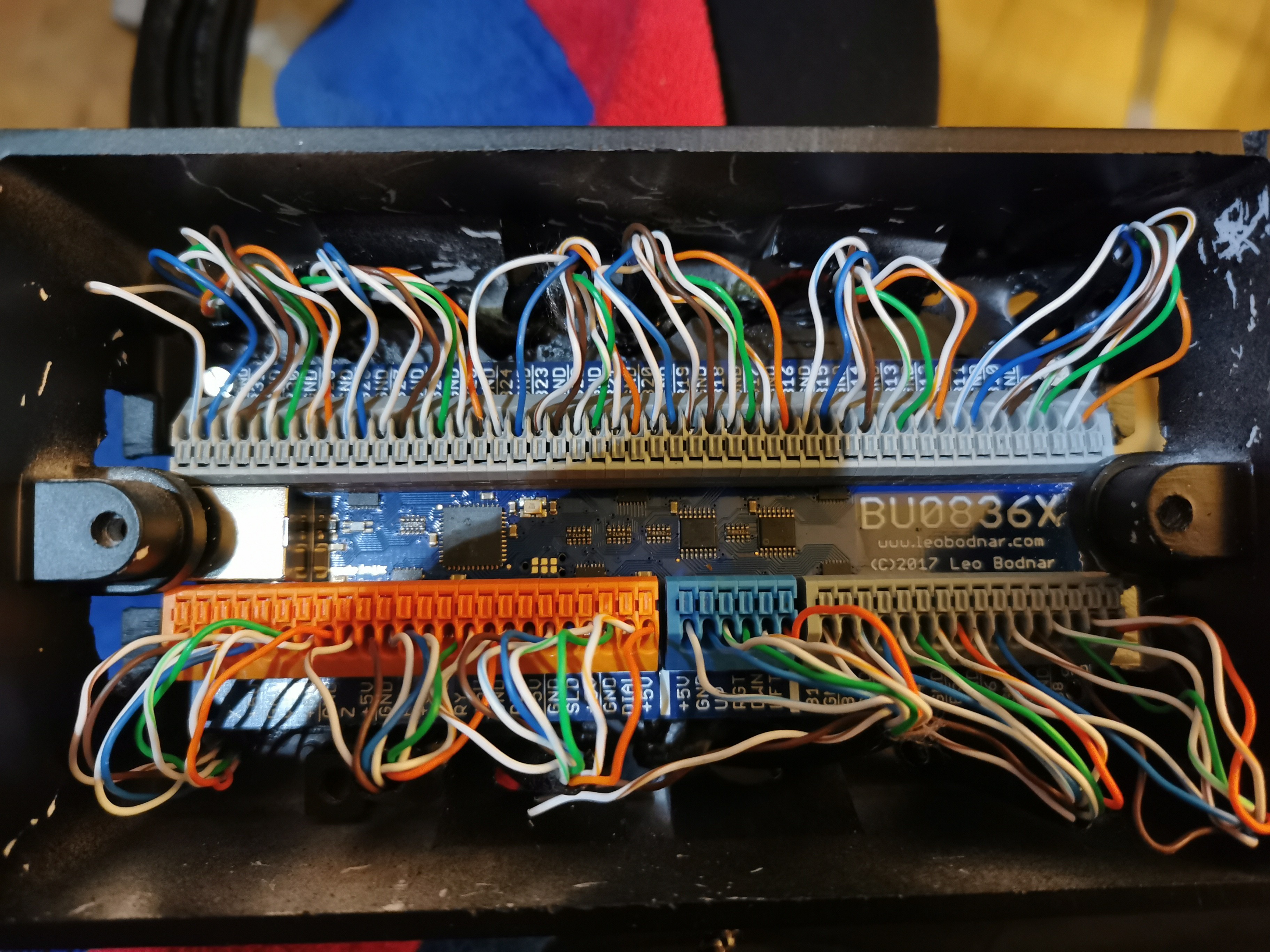
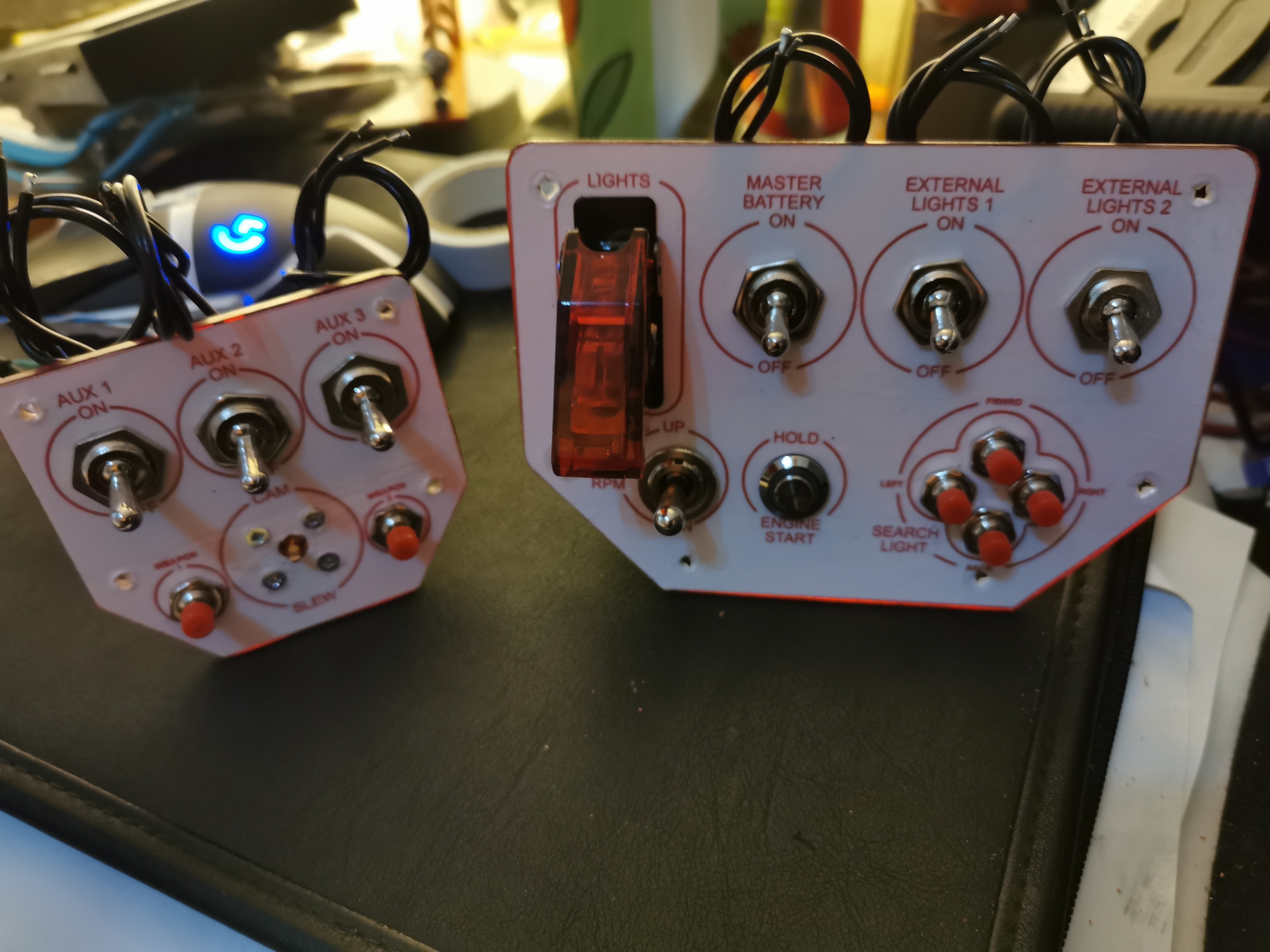
I will have two axis spare, as well as more than ten button inputs I can use for Rotary encoders or buttons. I like your idea of a "M134D minigun controller" so I might build an extra panel for that later. Thank you for the idea @hannibal
-
That is very cool mate. Please keep posting any updates here. I love DIY cockpits and helicopters. Your setup is very cool!
-
-
this is a great little hat switch board but it comes with no hat. I could have ordered one but I thought it slightly expensive so I made my own. Not as elegant, but it works perfectly.
-
DIY
-
did a bit more
-
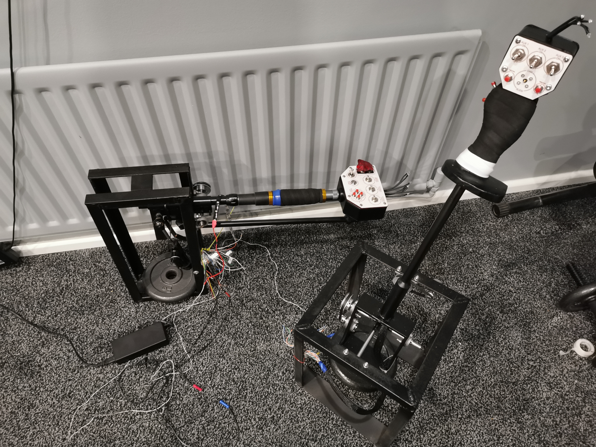
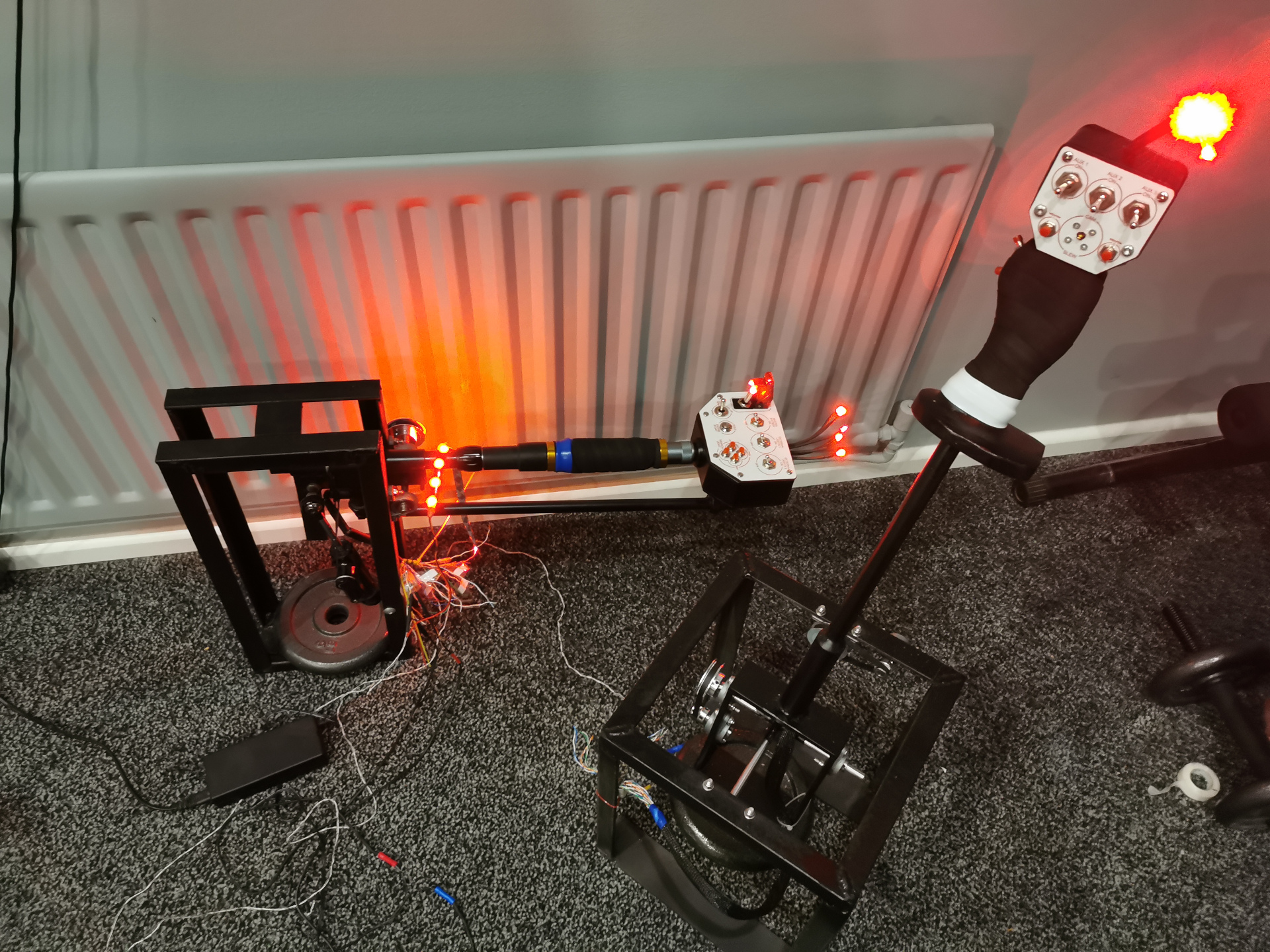
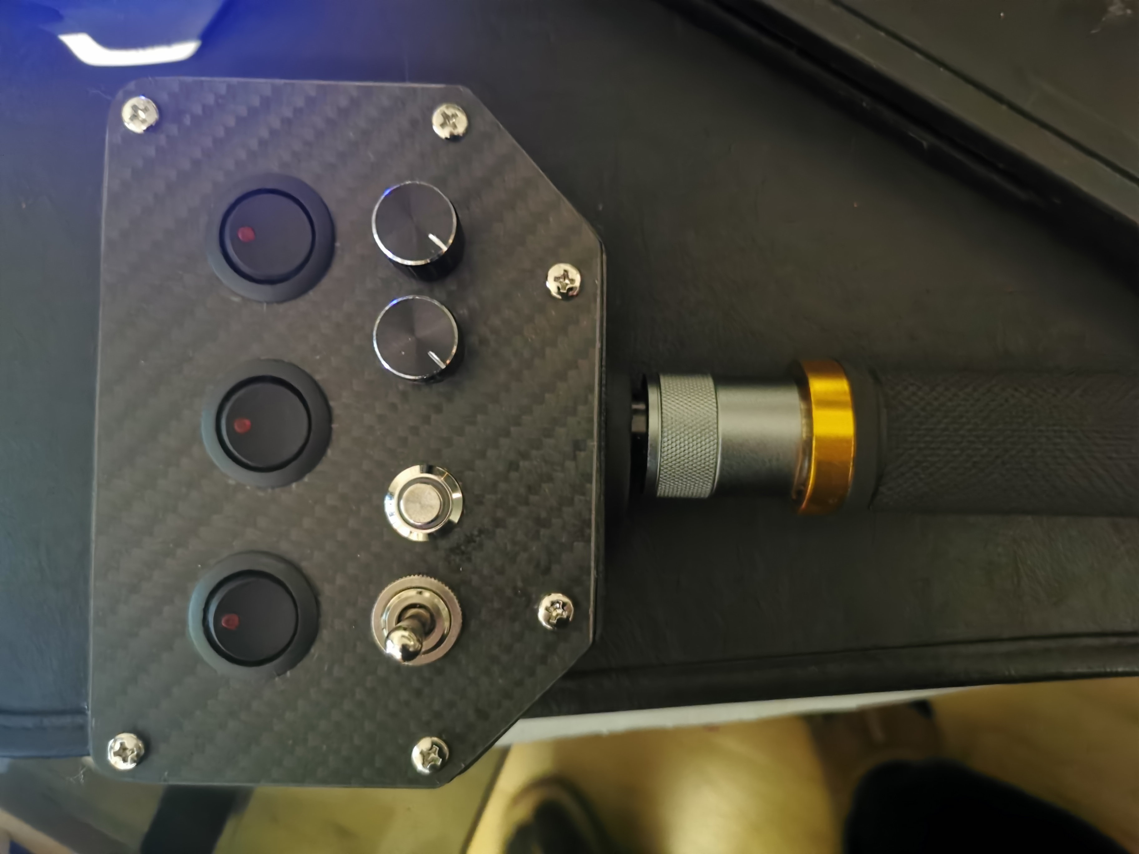
I started building my own peripherals. I am using basic hand tools so do not expect much. Plywood and PVC anyone? I was not too crazy about my first faceplate, and I didn't like the black switches so I made new ones I finished making the cage for the Collective I am experimenting here with gearing the axis, I like my solution so be kind So I started building a gimbal for my cyclic. The welds are garbage but so is my welding machine. Ugly but strong. I am not big on cosmetics, more concerned with how it works. Maybe I will work on making it pretty when it all functions. The gears are smooth and accurate. They are also not needed but I am doing an experiment with my build. I might add more pictures when I get more done
-

How difficult is it to fly and fight in it ?
atorque replied to jfri's topic in DCS: Ka-50 Black Shark
Find the right person to teach u. -
1.2.8 - External cargo/sling load not working?
atorque replied to shagrat's topic in Bugs and Problems
Does not work even with radar alt on. Tried everything and read everything and still I fail. Can anyone enlighten me? -
Maybe you could be so kind as to share the solution with the rest of us? The cargo cam does not work for me no matter what I try and I would love to know what the solution is.
-
Starforcks ate my hard-Drive!
atorque replied to 159th_Viper's topic in PC Hardware and Related Software
Simple solution. Get windows 7 and wait for something better than windows 8. Exactly what most of us did with windows vista. If you had asked me questions about windows vista I would not be able to answer that either because i only had it installed on my computer for about ten minutes before I decided to go back to xp and wait for something better. If windows follows their age old trend, the next os should be good, but the one after that will be garbage again. They dont listen to us, they burn their fingers, they turn around and listen to us. Next go they think they know better again, burn fingers again, and then are forced to listen to the people who know!!