Hempstead
-
Posts
473 -
Joined
-
Last visited
Content Type
Profiles
Forums
Events
Everything posted by Hempstead
-
http://www.adafruit.com/products/1303
-
Haha, I didn't say it's gonna be cheap. ;-) Now you know the part #, just keep checking eBay... I got a batch of 5 brand new ones rebranded as Lockheed Martin... for $5 each. I did make a rubber mold of the knobs and successfully cast a couple of them out of clear epoxy. However, I still can't find the D shaped tube inside the knob to accept the shaft of POTS. And making it myself is just way too much trouble.. I am sure somebody makes those and sells them to knob manufacturers. If anybody knows where to buy such tubes, please let me know!
-
http://www.peerlesselectronics.com/store/products/MS91528%252d001B.html
-
http://www.peerlesselectronics.com/store/products/MS25165%252d3.html
-
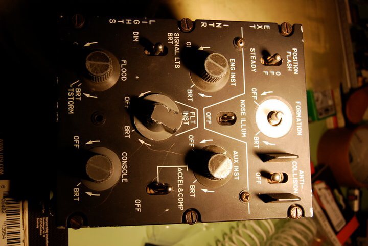
In case you are interested.... The middle two knobs of your lighting control panel are of the wrong type. See the attached picture of a genuine A10 simulator lighting control panel. I took the top middle knob off to show what how the backlight is transmitted into the knobs - by unpainted frosted circles under the knobs.

-

HOTAS Warthog and the o-ring
Hempstead replied to Daniel's topic in PC Hardware and Related Software
For ordering stock PTFE rings, just PM me and I will send you the info. for ordering. As to making thicker PTFE ring twice as thick as the original Warthog ring... the original Warthog O-ring is about 1.56mm thick. The stock PTFE ring is 3.175mm (1/8" thick), slightly more than 2x as thick already. Or do you mean that you want one that is 1/4" thick? I am not entirely sure if that will fit inside the Warthog without interfering with the upward movement of the spring piston platform. If your purpose is to have more spring force... I'd suggest making some steel rings and put them at the end of the main spring. Don't put it at the platform end. The platform has a groove to center the spring so the spring does not chafe against the platform wall. If machining a steel ring is a problem for you.... A hackish way of doing it is to take a steel wire (or bronze/brass wire you commonly find in HomeDepot for tying brushes in your garden), bend it into a ring of exactly the same diameter of the main spring, hammer it slightly flat, then use some tie wire to attach it to the end of the main spring. But I will not suggest welding/brazing the new ring to the main spring... it's kind of irreversible with welding/brazing, and the welding/brazing heat might affect the tamper of the spring... -
Question for panel makers - engraving.. how do you do it?
Hempstead replied to Devon Custard's topic in Home Cockpits
I don't think what the video demonstrated is the same thing as auto-zero in Mach 3. What the auto-leveller does is that it samples the z-height at multiple points on the board. Then PCB-GCode generates gcode with compensated z-height to account for the "unlevelness" of the board. A couple lines of code, and some ingenuity and you don't need a complicated z-height compensation mechanism anymore. Absolutely brilliant! -
Question for panel makers - engraving.. how do you do it?
Hempstead replied to Devon Custard's topic in Home Cockpits
Here's a SOIC 8 complete circuit with an MLX90333 in an analog output configuration I did 5 or 6 years ago for the DiHXY hall sensor for Cougar, years before the Warthog. The WxH of the PCB is 0.65"x0.65". The SMD resistors and capacitors are 0805's. Since it's a SOIC 8, the pitch is about 0.05", i.e. 50 mil and the width of the legs are about 15 mil. I used a 5 mil end mill. Due to runout of the spindle, the path it cuts is perhaps about 6 mil. The small traces to the capacitors are about 10 mil. except the power trace (20 mil) and you can see that not all the traces come out exactly 10 mil. The input/output legs are soldered in for IDC 0.1" pitch connectors. I would say anything smaller would be pushing it with this setup. It's doable, but I must tell you that I had to tweak the backlash nuts of my tiny desktop mill so much that I actually ruined the backlash nuts. It's not very health for this mill to run such tight backlash! It actually would bind at the end of the ACME screw run. You probably would need some precision double nut ball screws to run anything smaller. But the good news is that very few sensors are smaller than SOICs (Unfortunately newer MCUs are often smaller LQPF 0.5 or even BGAs). This is my prototype circuit so I left it bare without any coating and it oxidizes quite a bit.
-
Question for panel makers - engraving.. how do you do it?
Hempstead replied to Devon Custard's topic in Home Cockpits
The right side is the real one from the real A-10 Simulator (won the bid on eBay, it's the whole self-contained lighting control unit including all the electronics and they use AC Variable Voltage Transformers instead of POTS!!! OMG, how much is one of those things costs when new???!!!!). The left side is my reproduction. Laser engraved on the front, pocketed, outlined cut on an CNC'd RF-45. The large recess pocket on the back is for PCB for LED lighting (the original uses a phenolic board with aluminum foil as tracks and incandescent bulb for backlighting). The large recess was milled with a 3/4" and a 1/4" Osrund Carbide upcut endmil. Then, the whole thing is glass bead blasted. Still needs to white fill the lettering, then paint the whole thing black... and finish my USB controller firmware. I write my own USB firmware for it using Atmel's evaluation board (and a Arduino Due, all 32bit ARM chips). It contains a FreeRTOS real time OS in it. And the whole thing runs multithreaded. It even has a running average digital filter to smooth out the noises. And it also has a over-sampling to "artificially" increases resolution to 16 bit ADC (to be honest with you, I think the oversampling is gimmicky). It is also capable of reading the Warhog/Cougar sticks (but only on selected models of Atmel chips that contains SSC modules, like SAM4S or SAM3X on Due). I am looking into support SAM4E chips, which has a real 16bit ADC on it, as soon as I get my hands on one of the boards. The predecessor of this firmware powers my CH rudder, of which TARGET accepts it and I program it using TARGET and combined it with my Warthog. It's been doing that flawlessly for the last 3+ years. I will OpenSource it soon (the Rack Mount server for it is already on my desk).
-
HOTAS Warthog and the o-ring
Hempstead replied to Daniel's topic in PC Hardware and Related Software
I still have them in stock and will make more if necessary (current number of stock is in the 70s... I went hog wild making them one weekend ;-). So, if you wish to buy some, send me a PM. Although the mailing and material costs have gone up quite a bit since I started making them. I am too lazy to raise the price. I am fine with not losing money on it. So, they are still USD $8 apiece. -
Question for panel makers - engraving.. how do you do it?
Hempstead replied to Devon Custard's topic in Home Cockpits
I do use a CNC to do PCBs for the Cougar DiH hall sensor. It's a SOIC 8 chip. Works just fine. 10 mil trace, no problem. However, I have to tell you that for finer pitch... tough... It wouldn't be easy to do 0.5mm pitch for, say, Atmel SAM4S with LQFP 0.5mm (not impossible). And the flatness of your table and fixing of the PCB has to be absolutely flat that it's not easy for large format. A vacuum table would be great, but for small PCBs, I mill some aluminum hold down for them (just a flat plate of aluminum with a rectangular windows on it and another milled flat backing plate to clamp the PCB flat). And obviously, your machine be better trammed perfectly... or you will end up one side cut too deep, one side no cut at all. This is mainly why larger PCBs are very difficult. Professional PCB milling machines solve this problem by using depth sensor, which you would not have with a regular CNC mill/router. Also, your machine backlash better be tightly controlled. See, if your machine's backlash is 5 mil and your trace width is 5 mil... you might end up with no trace at some places. A tip for after milling the PCB... you will end up with some copper burrs that you need to clean up. I find that using a fine grit Japanese water stone for knife sharpening works perfectly. Wet the stone with some water, press the copper side down, run a couple of passes and all the burrs are gone. A good blast of compressed air.... and you are good for soldering. Also, if you use Windows EagleCAD's PCB2GCode to generate the GCode and your mill is using Linux EMC... you'd need to run dos2unix on the generated GCode to translate the Windoze CRNL to NL, otherwise Linux EMC will err out and spit out some weird/confusing error messages. -
Question for panel makers - engraving.. how do you do it?
Hempstead replied to Devon Custard's topic in Home Cockpits
I bought my laser cutter specifically for engraving panels. But then came to use it for making the PTFE rings for Warthog. What I find it most useful is to cut templates.... No more going to my drafting table then jig saw the templates very carefully, then sand them to size! Draw the design in CAD, laser cut whatever template I need on a thin sheet of plywood, then plasma cut made easy!!! No more wiggly cuts due to trembling hand or sneezing! I also use it to cut and actually pocket (rough multi-pass engraving) the Hall Sensor base I am making. I used to make this w/ a 3d printer, but found the el'cheapo 3d printer I have very temperamental and unreliable. Well, instead of silk screening, you can laser engrave rubber stamps for lettering on curved surface, cut complex masking for spray painting/decal.... numerous uses! If you ain't got a hammer, nothing looks like a nail! -
Question for panel makers - engraving.. how do you do it?
Hempstead replied to Devon Custard's topic in Home Cockpits
I have tried all 3. Silk screening, unless you have large quantity and some good and expensive machines, it ain't worth the trouble. The art supply store sold light sensitive stuff isn't exactly designed for precision. So it requires some trial and error experiments.... Not exactly time saving for one off or small quantity. CNC engraving is quite tricky to get right unless you just want stick fonts. If you are getting plastic melting, like WarHog says, get some good quality carbide V cutters, and try to rig up a flood coolant system. My first attempt in engraving polycarbonate lasted 3 seconds and cost $20 without flood coolant. Even with flood coolant, getting very fine details is quite a challenge/black art. I find laser is the easiest to produce one off or small quantity, reasonably detailed panels. I use laser to engrave the panel face, then CNC mill the cut out and outline (laser cutting thick panels produces slanted edges and you can't really do pockets). Unfortunately most routers are quite difficult to rig up a flood coolant system due to their design of having stepper/servos pulley, belts/ACME screws on the bottom. Bigger machines suitable for flood coolant system is a bear to rig up. I actually build a 4'x6'x8' enclosure for my RF-45 (yes, you read that right, foot, not inch) and then rig up a 50 gallon fish tank for the coolant. If you have the $$$ check out Tormach. But, be forewarned, real CNC is a long learning process. -
Hotas Warthog Joystick Thread size? ...and more
Hempstead replied to benargee's topic in Thrustmaster
http://www.amazon.com/Gardena-39035-8-Inch-Garden-Connector/dp/B002VED3KW/ref=sr_1_1?ie=UTF8&qid=1400613035&sr=8-1&keywords=39035 -
HOTAS Warthog and the o-ring
Hempstead replied to Daniel's topic in PC Hardware and Related Software
Agreed. The 4 holes and the 4 poles on the spring platform is mainly the cause of sticktion & center play. These 4 holes are slightly tapered to prevent lock up against the 4 poles. The taper is needed to increase the contact area between the holes and the poles, but at the price of center play. I actually CNC milled a solid block of 6061-T6 aluminum and precision reamed the hole to 5.01 mm diameter (the poles are 5mm diameter) making a new spring platform in an attempt to eliminate the center play. That was a beautifully machined part, but a spectacular failure nonetheless. Because, sure, there is absolutely no center play I can detect anymore, but it completely binds the 4x poles! This, of course, is an extreme case of indication where the sticktion is coming from, i.e. I proved that I can increase the sticktion to 100% binding the poles so the Warthog stick won't move at all. However, the ring does contribute a very small portion of the sticktion... but it's so small that I must tell you that the PTFE ring will NOT improve the sticktion situation. -
HOTAS Warthog and the o-ring
Hempstead replied to Daniel's topic in PC Hardware and Related Software
No big hurry, guys/gals... even after the recent in rush of orders, I still have 8x PTFE in stock. And I have already ordered another new batch of raw PTFE sheet enough to make another 36x rings. I will be around to provide this service, unless someone else wants to take over the service or start a business. It seems that GoogleMail recently changed it's SPAM filter policies so that I had to fish out a couple of your emails out of the SPAM folder. It's not as convenient and fool-proof as getting a ding on my cell phone as soon as the mails are delivered. If I don't respond to your PMs or emails within 24 hours, please send the PM/email again (I might have missed it among the vast number of "enlargement... SPAMs" in the SPAM folder. ;-) And, perhaps check your SPAM folder too? -
HOTAS Warthog and the o-ring
Hempstead replied to Daniel's topic in PC Hardware and Related Software
Here's the specification. If you wish to make it in small or large quantity. You are most welcome to make it yourself and sell it too. The outside diameter is 64mm, inside is 59.5mm nominal. Thickness is 1/8" (3.175mm or about 3mm). The material is PTFE (Teflon) sheet. Nylon sheet should do just fine, except that Nylon is not as slick as PTFE so you must grease the hell out of it. With PTFE, technically speaking you don't even need to grease it, but I would still advise greasing it just in case. Why not, right? If you do start making it and selling it commercially, please drop me a note so I can stop making it and refer the business to you. I will be glad to get out of it. Correction ----------- The spec. Should be OD = 64mm, ID=54mm, thickness=1/8". -
HOTAS Warthog and the o-ring
Hempstead replied to Daniel's topic in PC Hardware and Related Software
#Pand, Please check your PM. Apparently, I would get an email when somebody PM me on the ED forum. So, if you wish to purchase PTFE O-rings, please PM me on ED forum. I still have 16x in stock. Like I said, I do this as a service to fellow Warthog owners, and it's currently laser CNC cut, so I can make as many, or as few as there is stock PTFE sheet I can purchase at reasonable price. Please note that, since it's cut out of solid 1/8" thick PTFE sheets and you can flip around and use the other side, you really don't need to buy a lot. I have never received a failure report. Please limit your purchase to 2x rings per Warthog so we can serve more fellow Warthog owners. Thanks! -
I need rudders that "sticks"
Hempstead replied to Taproot's topic in PC Hardware and Related Software
I simply take a long 1/2" D stainless steel rod and put it in front of the two rear legs of the table, then wedge the rudder against the rod. Works like a charm, and the position of the rudder is just right too. -
HOTAS Warthog and the o-ring
Hempstead replied to Daniel's topic in PC Hardware and Related Software
I have been making solid PTFE (Teflon) rings for this since 3 or 4 months after Warthog came out, now CO2 laser cut. You just take the old ring out, wipe the residue glue clean, put the new PTFE ring in, grease up, reassemble, and go. Since it's cut out of a solid PTFE sheet (1/8" thick), it's stiff enough to wedge itself in place without any glue, and you can flip around and use the other side too. I only sell it on the Warthog World forum as a service to fellow Warthog owners who run into the same trouble w/ the ring. I must have sent out at least 40 or 50 of them worldwide for the last 2 1/2 years. No failure of the PTFE ring reported yet. Since my goal is not to make money out of this, I charge only USD $8 apiece, S/H included w/ USPS first class mail. Priority mail would have cost an additional $20 per shipment.... not worth it. Since I don't have a desire to turn myself into a minimum wage worker, I don't really feel like "advertising" it. But seeing people here resorting to super glue... My heart ache for you. If you have a need of it, send me a PM on Warthog World (the site is currently down though). Try your luck w/ PM on this forum if you want. But since I rarely read this forum, your mileage may vary...