Nikolas_A
-
Posts
119 -
Joined
-
Last visited
Content Type
Profiles
Forums
Events
Everything posted by Nikolas_A
-
I have a F-18 panel for sale https://www.ebay.com/itm/164014543433
-
The first type of switch in your pdf is On-On-On, not On-Off-On
-
My suggestion is to read the specs (MS25212 for panels, MS33556, MS33638, and MS33639 for gauges), they will give you solid reference dimensions. Also, it's better to dimension in imperial units. E.g. if you use a photo for reference and you estimate a dimension at 64mm, it might seem right to round it to 65mm. But since it'a an american part, it's more likely to be 63.5 (2.5").
-
Interesting but a bit OT. There many ways to mount a bezel on a display that is larger than it. The problem is the "sandwitch", the gray part in your render that shows within the bezel. In the real MFD you don't see that. If we find a square display the right size we will not see that. The point is to mount the bezel directly on the display, without sandwitching the panel in the middle.
-
Yeah, I was thinking the same. I would like to see a drawing. I might be interested
-

My engineering approach to a Hornet pit build project
Nikolas_A replied to Alex_rcpilot's topic in Home Cockpits
Nice, but why don't you start a new thread instead of posting in someone else's? -
Yup, looks about right! Now, I need three black 6-32 screws and wiring.

-
Did you get around to modifying the switch?
-
Yes, the leght is a multiple of .375". The width according to MS25212 should be 5.75". It is not. It can't be because the throttle is in the way. The other panels under the throttle are 5.75". Did you even look at page 3? Sorry for the derrail LynxDK
-
Yup, only the EXT LT is not a standard size, hence that discussion... See Stang's drawing on page 3.
-
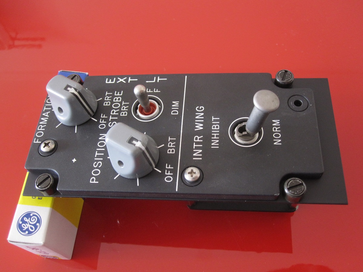
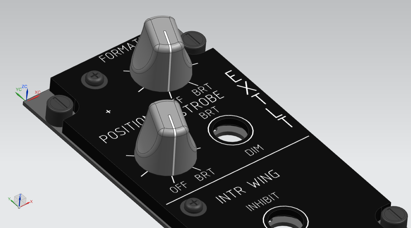
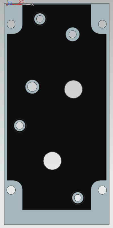
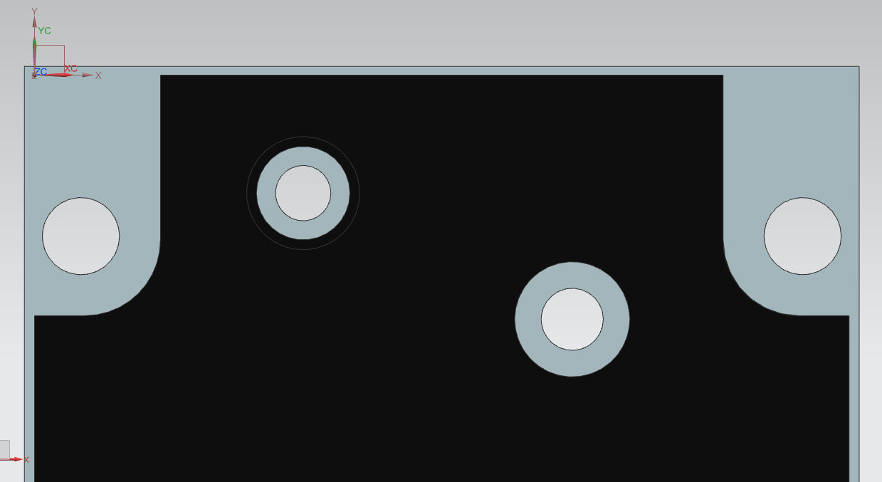
Ok guys, I put the real EXT LT lighting plate I have on the CNC and measured it with a digitizing probe. I made a 3D model, when it's complete it will be available if anyone wants it. I like your way of thinking but the result is definitely wrong. The lighting plate is 68.56mm wide, so the mounting plate cannot be 63.41 I modeled the mounting plate using Stang's figure of 72.63mm. It looks a bit wider than it should be. The DZUS holes don't center in the arcs of the lighting plate. If I make it about 2.3mm smaller the DZUS holes are centered and the distance between them is 60.748mm (2.39") which makes me believe the DZUS rails are 2.4" (60.96) center to center.
-
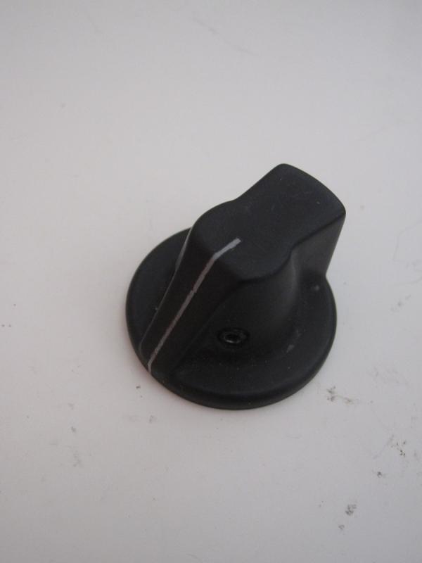
It doesn't have any markings, but it fits the EHC FPB2485-04BA1 specs
-
I got a few of those (real) knobs. One is used in the F-16 but the A-10 uses more. I'm selling the extras for 8€/pcs. Takes 1/4" shaft, backlitable
-
I did something similar but using Heli-coils instead of brass inserts, and just press fitting the acrylic in the monitor bezel. I cut it about 0.5mm wider and taller than the monitor bezel opening and it jammed nicely in there.
-
Yup, I got the same displays for the AN/ARC-164 and they make for a very strange font. It was the only one that could fit in there, though...
-
A-7 HUD control panel https://www.ebay.com/itm/163816962001 F-18 MPCD bezel https://www.ebay.com/itm/163816973990
-
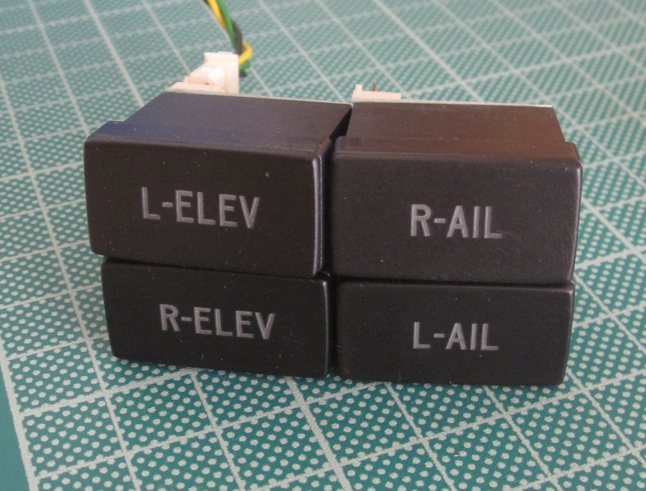
I ordered those to complete an A-10 trim panel. Unfortunately, even though I told them three times AND send a drawing, they still managed to engrave the text horizontally instead of vertically. So, if you're building a generic pit or an A-10 but can live with that inaccuracy, those might be for you. I'm asking 35 euros + 10 for shipping (I don't know if I'm supposed to post these there since it says PC hardware. I thought it was more appropriate here)
-
But that's good. If you send 6 "left" keypresses you know the vitrual sitch is in its leftmost position. Then you read the position of the physical switch. If it is in, say, the 3rd position, you send two "right" keypresses. Then, whenever you move the physical switch, you send the appropriate keystrokes. I don't know what interface you are using but with most I know it can be done.
-
What happens in the virtual cockpit if you send the "left" key too many times? Does it go to the leftmost position or does it go around? If the former happens, you could have your software send 6 "left" keypresses to initialize and go from there
-
Did someone here buy them? If yes, I could buy a couple...
-
Some more parts of sim building interest (panels, indicators, switches, encoders etc) https://www.ebay.com/sch/nik_anas/m.html?item=163307378841&rt=nc&_trksid=p2047675.l2562
-
Some more: https://www.ebay.com/itm/163293575050 https://www.ebay.com/itm/163293584019 https://www.ebay.com/itm/163293584390
-
16 segments could be close: https://gr.mouser.com/Optoelectronics/Displays/LED-Displays-Accessories/_/N-6j73b?P=1z0j22y&Keyword=segment&FS=True
-
I'm a metric guy too, but when working with american made parts it's best to work in inches. You get to understand what the designer was going for by rounding to the nearest decimal inch or fraction. Thanks for the dims, I'll crosscheck them with my estimates. If you want I can measure the Ext Lt for you and scan it too, let me know
-
Hello, are your drawings based on the NATOPS foldouts or do you have any hard dims? The reason I ask is I have a real Ext Lt panel and I want to build the backplate for it. The thing is the panel's width (as well as Gnd Pwr) doesn't conform to MS25212. So I'm using MS25212 spacing (multiples of .375") for lenght and adjusting the width so that the DZUS studs have equal distance from the panels in both directions. But if I could find hard dims it would be better. Also note that in the bottom the backplate is a bit (probably .375") longer than usual. I've seen in both in sim and real photos. Finaly a suggestion: under potentiometers or rotaries you want to make a white circle so that the backlight shines through the knob Cheers, Nikolas