lesthegrngo
-
Posts
1245 -
Joined
-
Last visited
Content Type
Profiles
Forums
Events
Everything posted by lesthegrngo
-
Guys, since Windows stopped recognising my 1060 card that was installed alongside the 3070, I now have insufficient graphics outputs for the six total monitors I have I heard that Display port screens can be daisychaned, which doesn't help me as none of the screens use DP, only HDMI. Is there some way to connect more HDMI devices and still have them as individual screens? Cheers Les
-
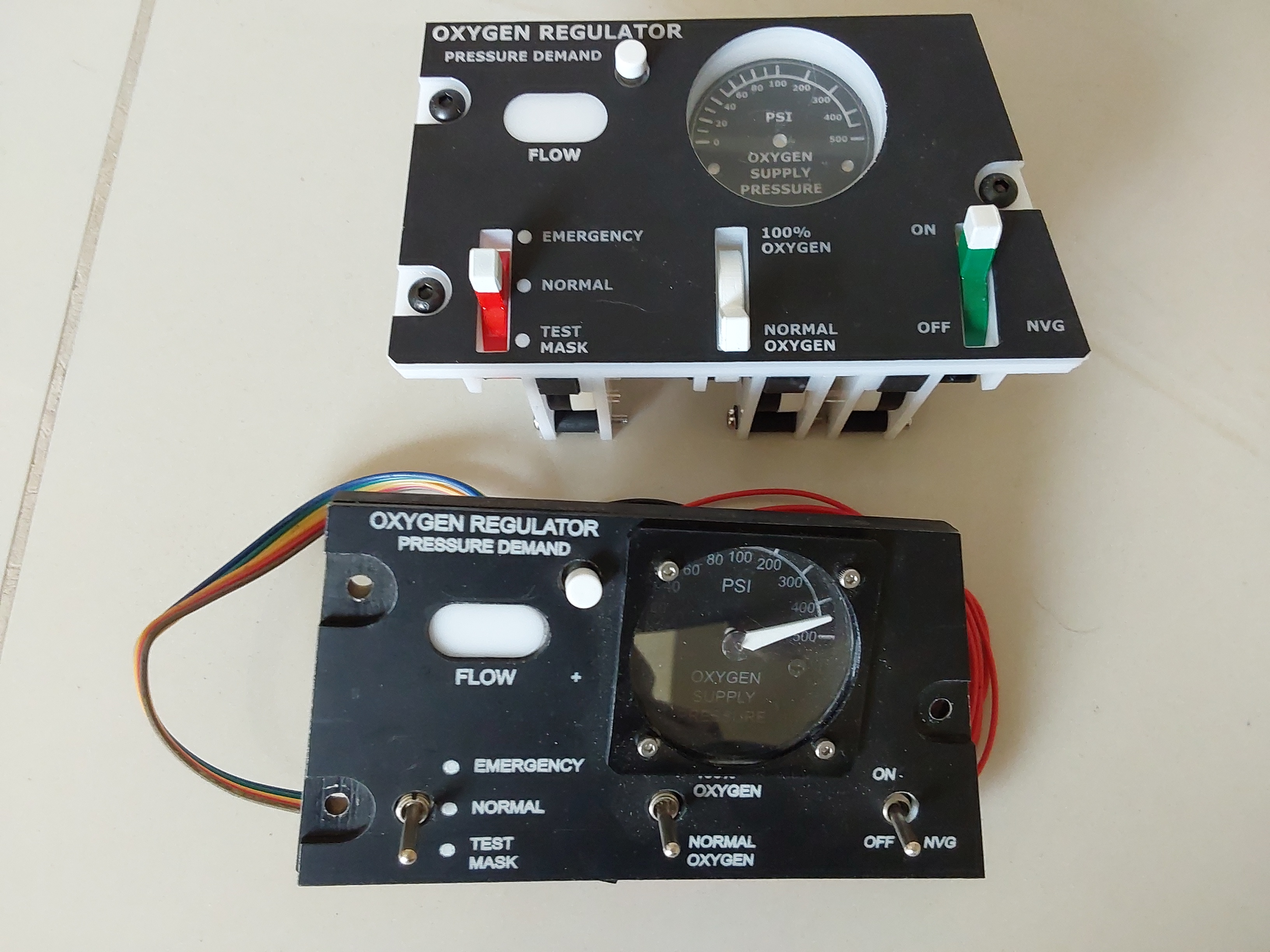
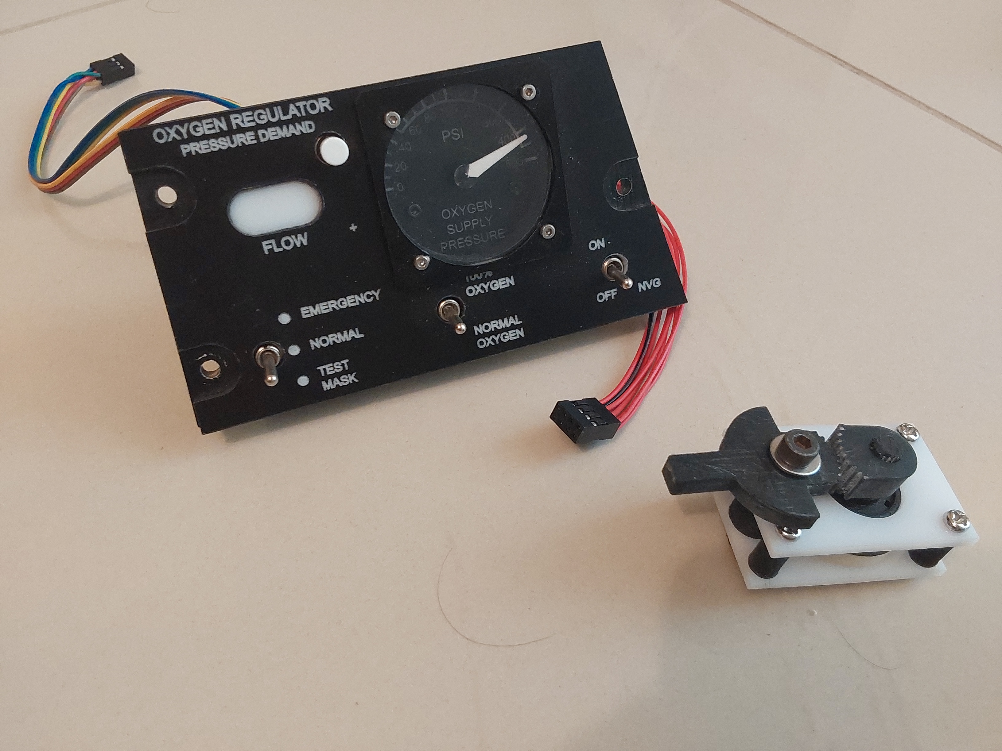
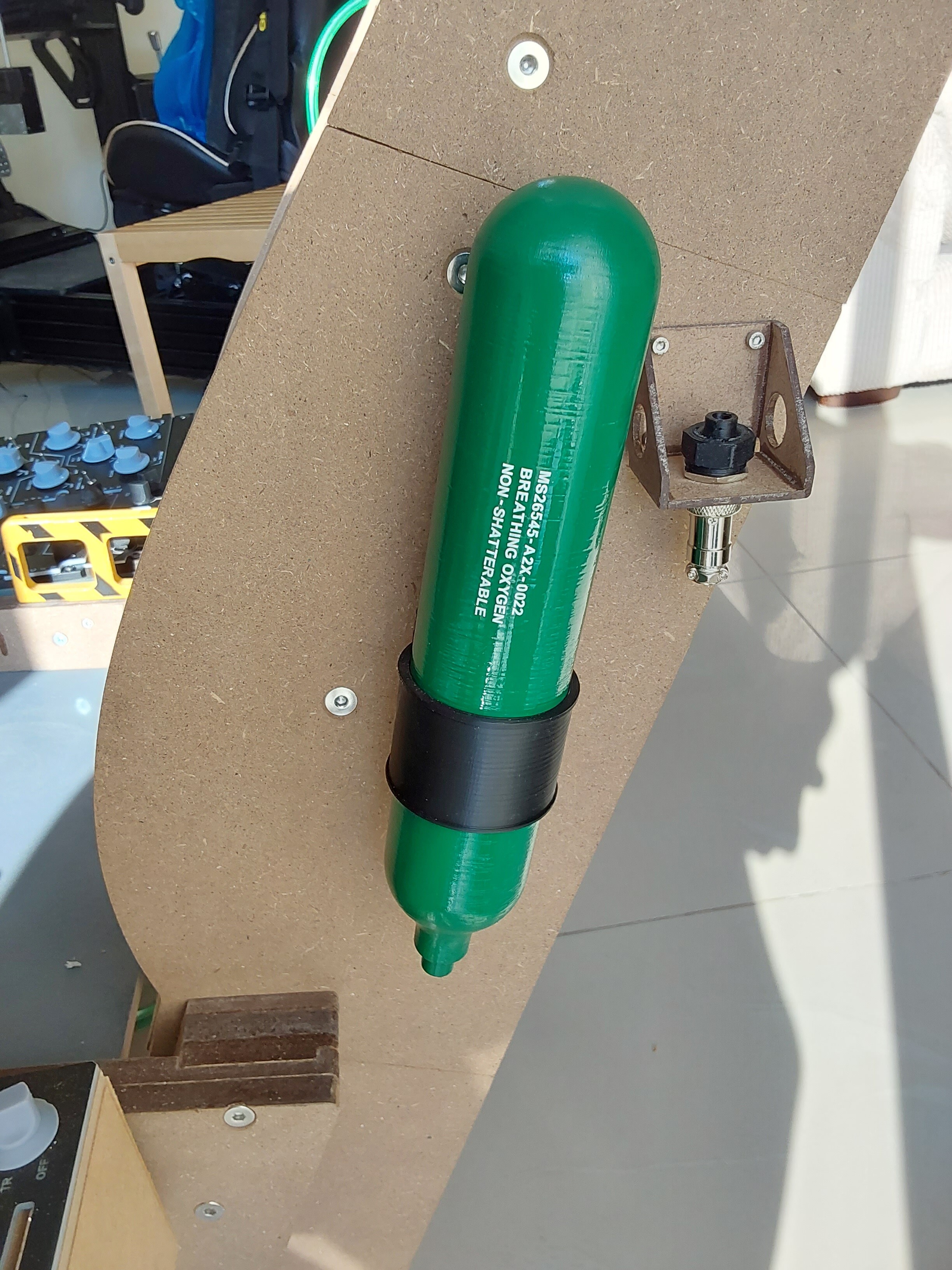
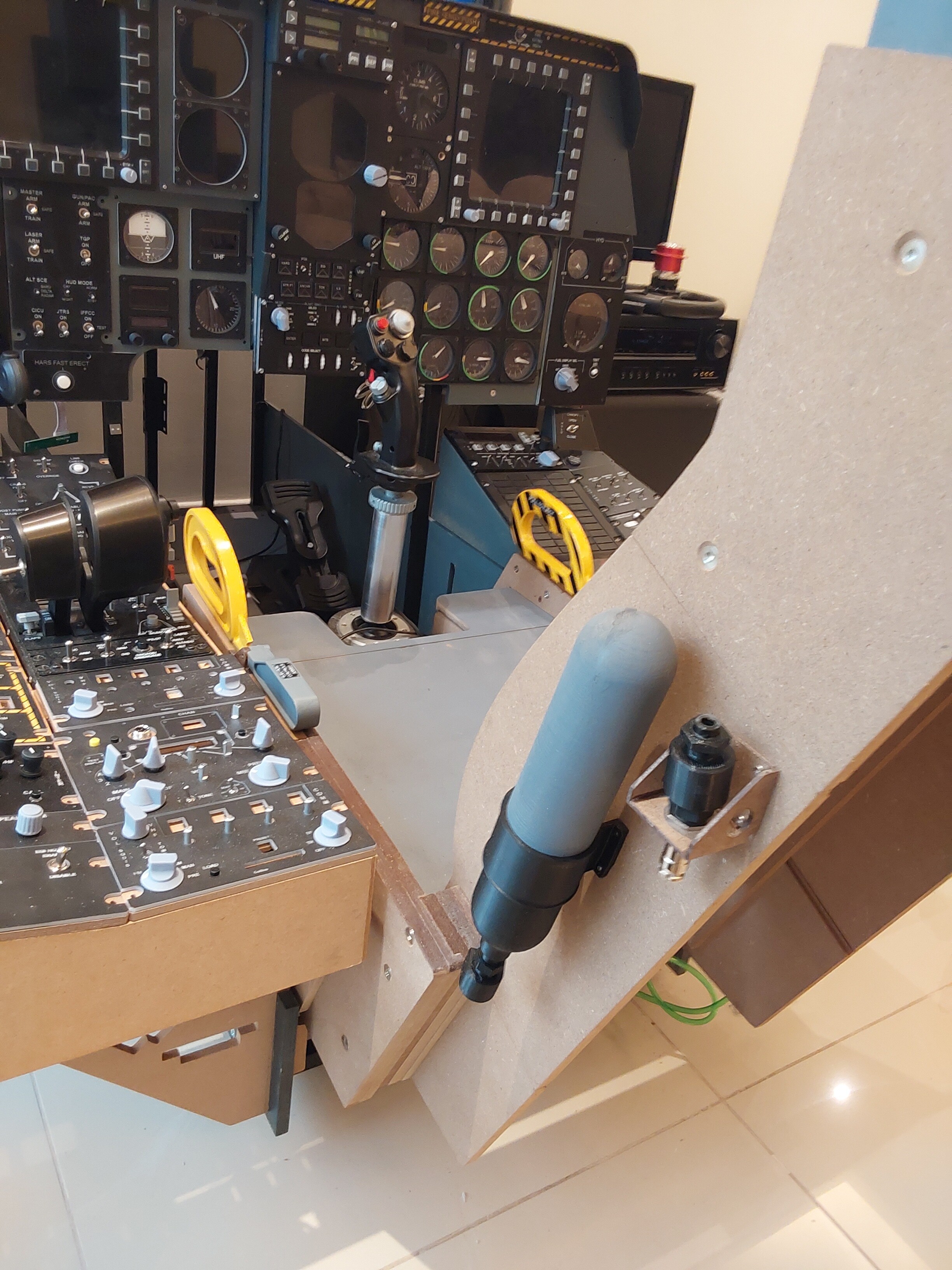
Here's the new oxygen supply panel, works great and looks the part too I still have to finish the little details and electrical connections plus stepper but a lot of that can be reused from the old one

-
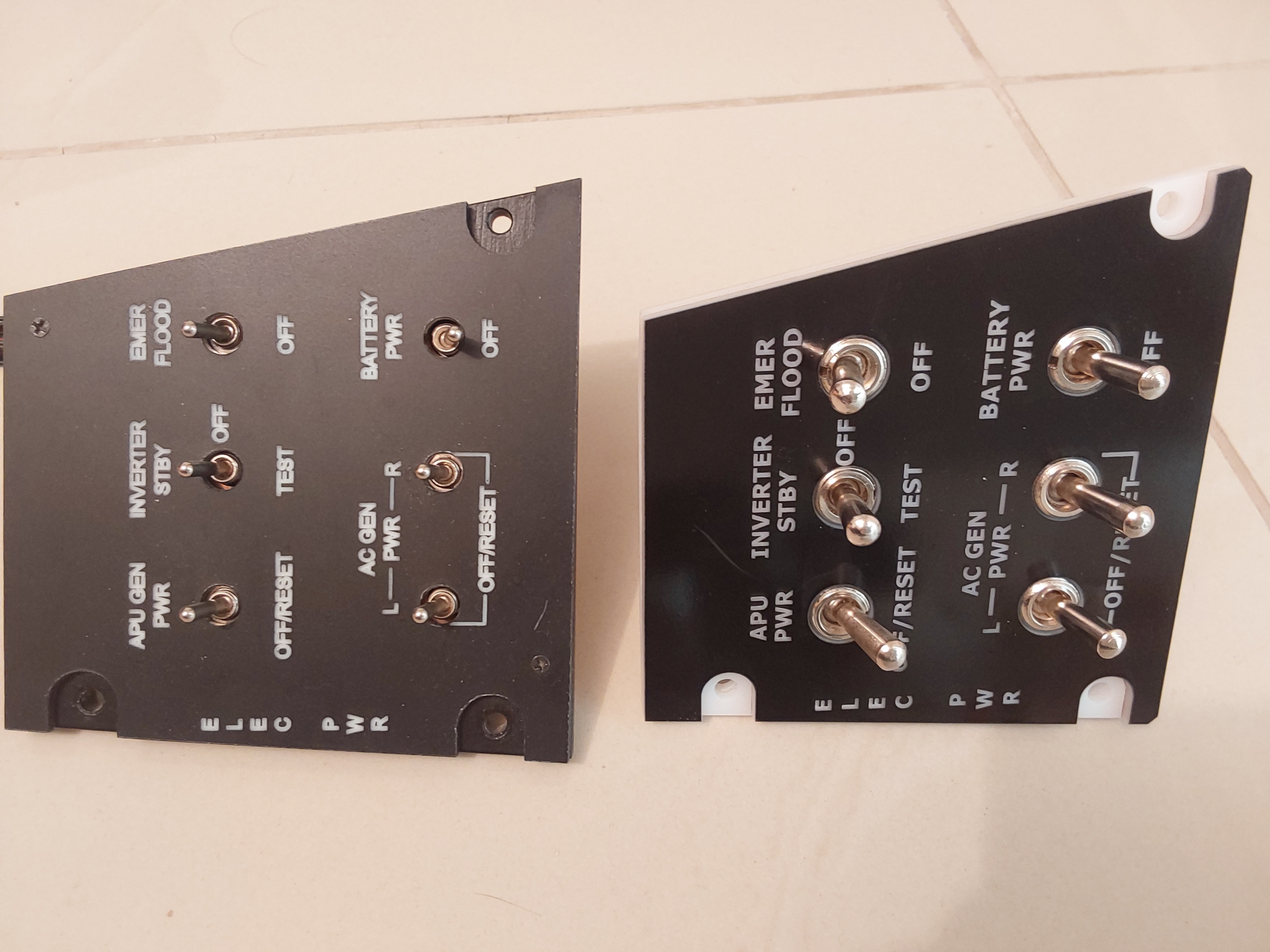
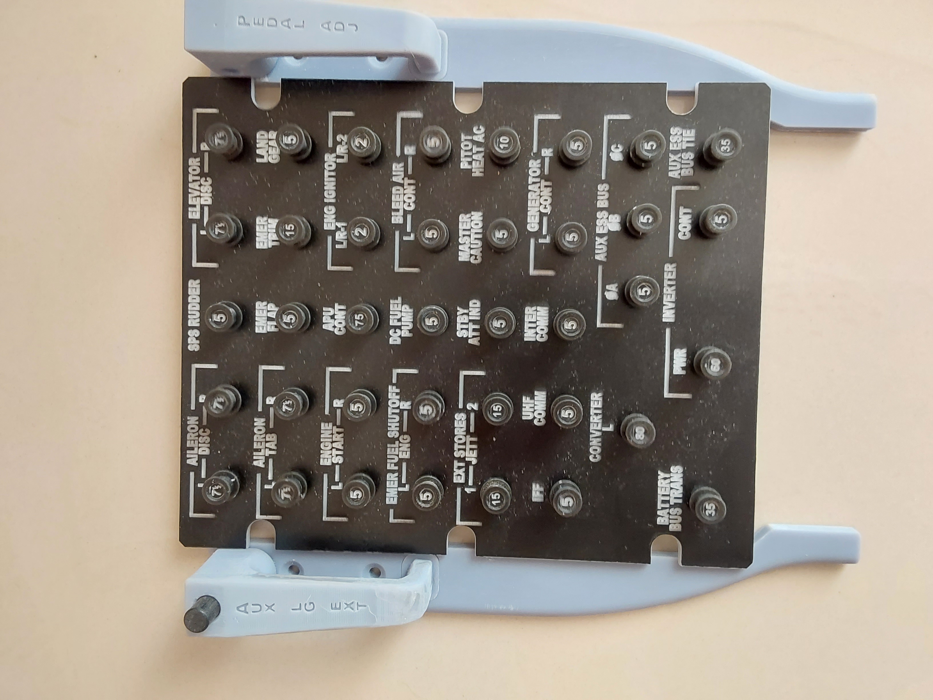
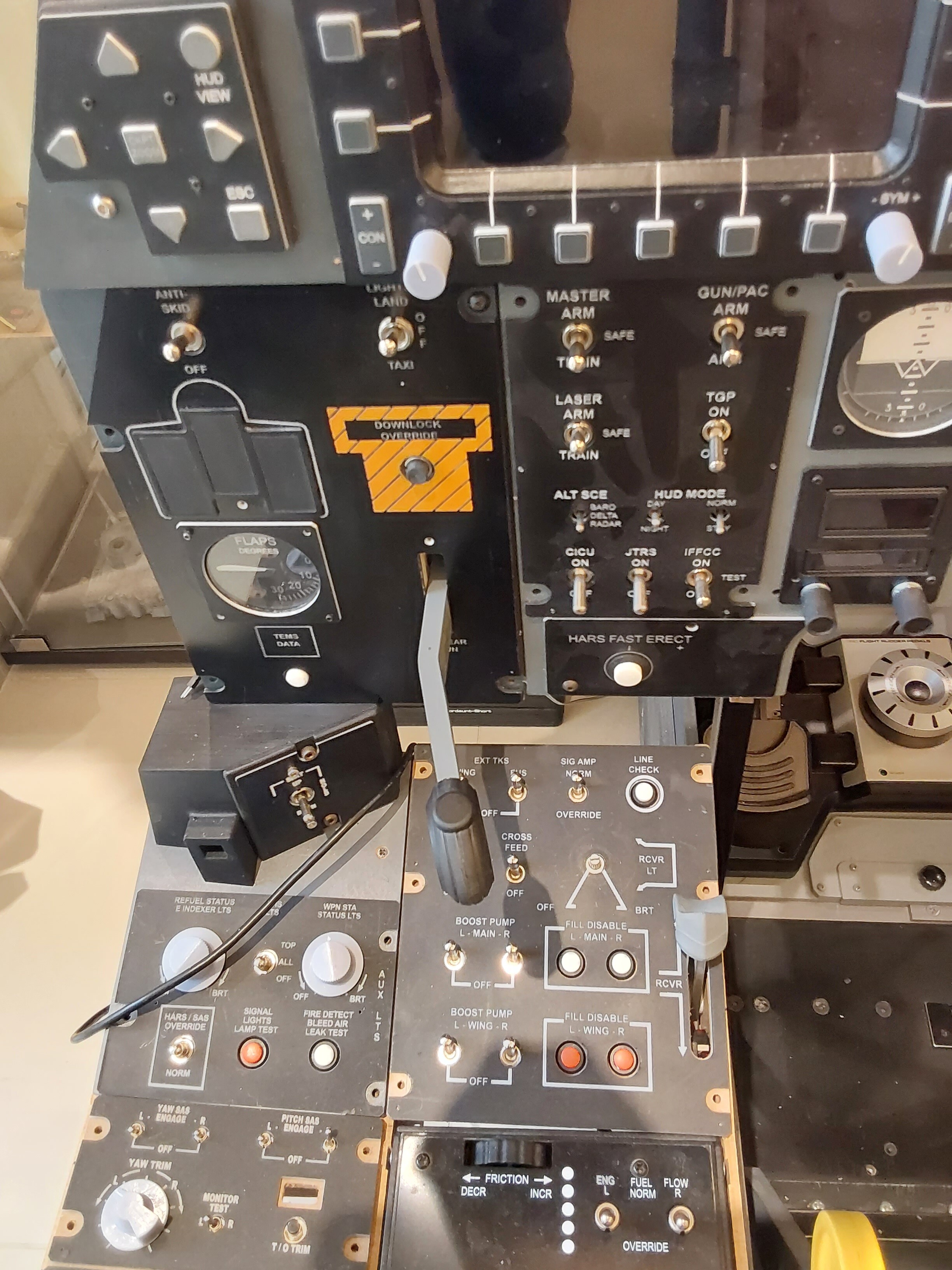
Here are the old and new electrical panels; the difference in the size of the switches is massive. I obvioulsy have to paint the new version's backplate Les
-
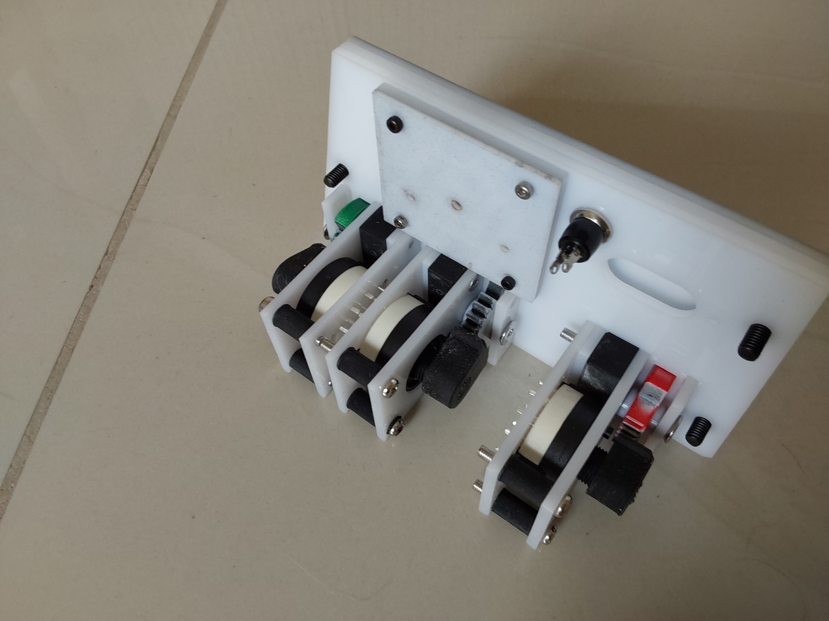
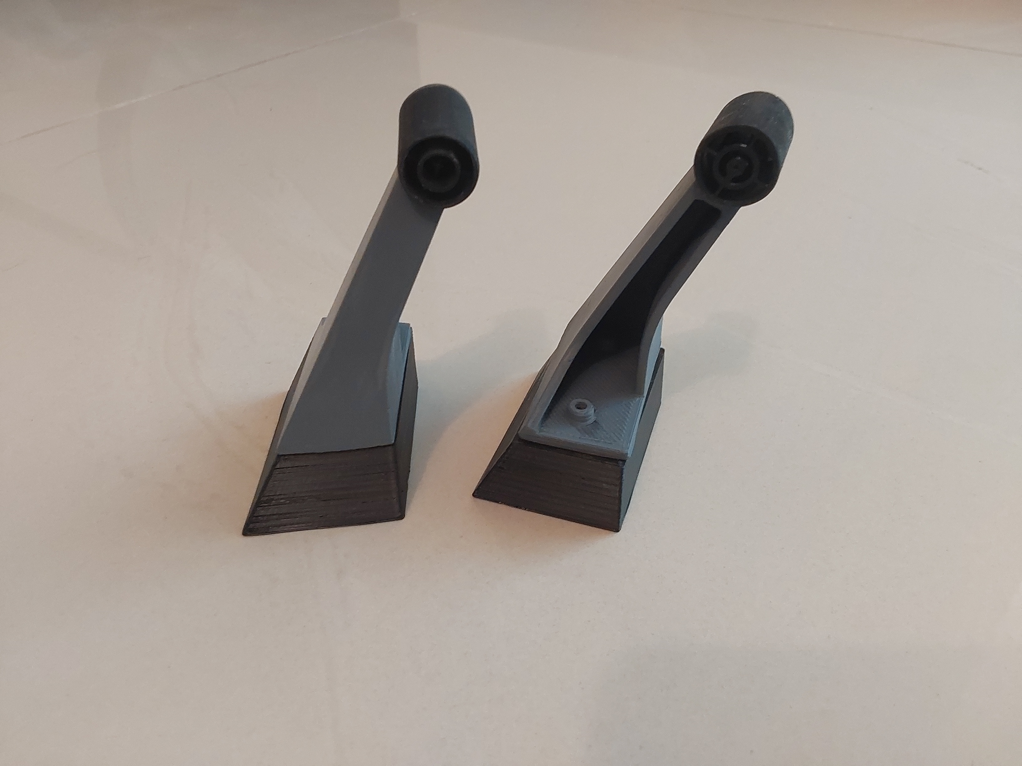
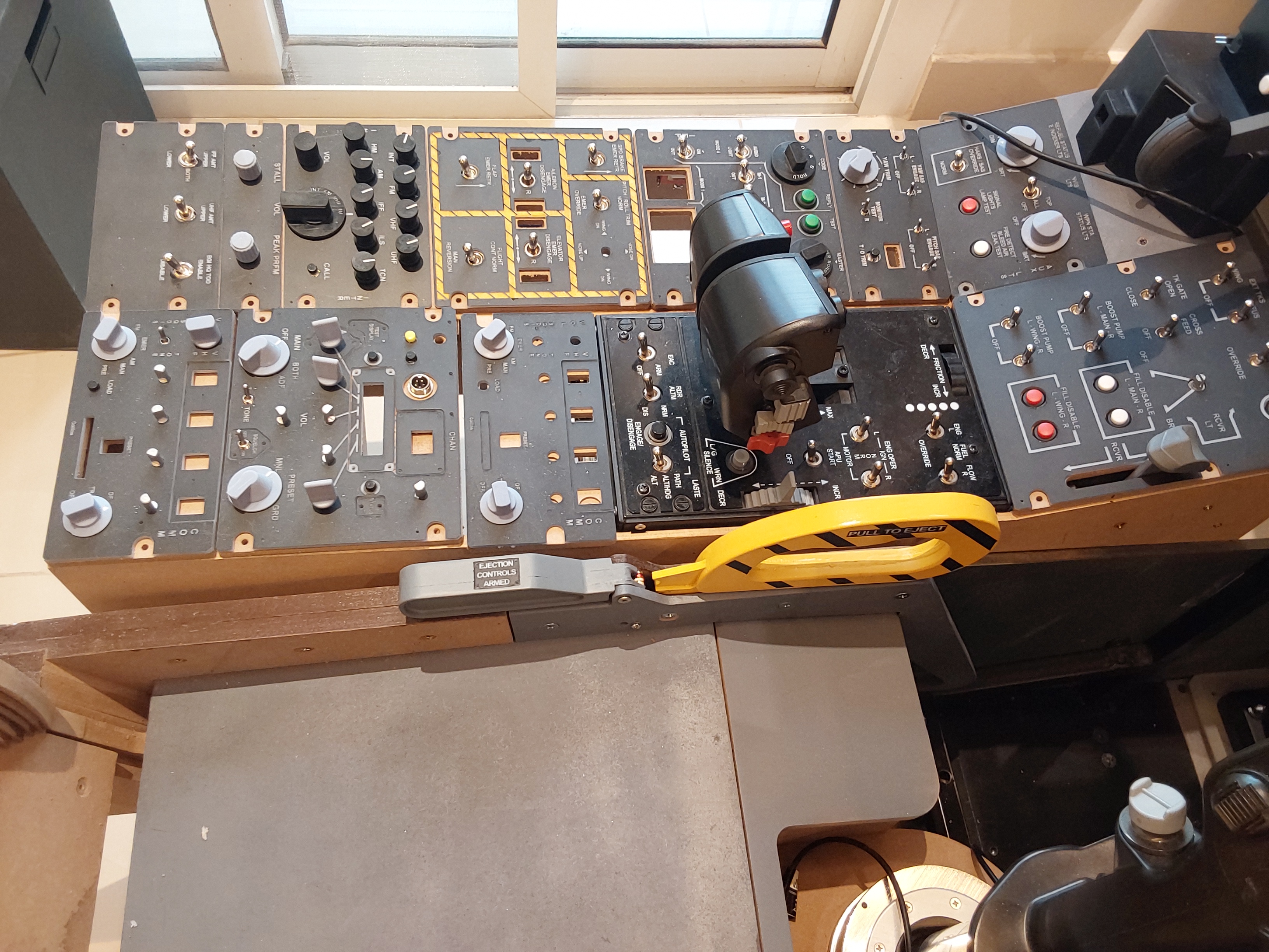
Hi again all I'm still waiting for the 0.66 OLED modules I ordered months ago for the UHF and VHF radio panels, so have started looking at other bits and pieces to work on. One of the things that I did when I started out was to use the small toggle switches you can get quite easily, as they were easy to incorporate, came in differenet 'flavours' (On-Off-On, On-On etc) and could be made to be soldered directly to the PCB, making On-On-On switches a breeze as well. The problem with them is that they are small, which means they end up with a slightly toy like feel. Additionally, in some cases they are entirely the wrong type of switch, for example I used them on my Oxygen panel in the picture below, when reference to pictures of the panel show them to be a rotary type lever mounted vertically. I suspect that in real life two of them are actually potentiometers or RVDT's, and the third a three position rotary switch. None of these are available as far as I could see so I deceided to play around with what I have and see if I could replicate them. Looking at the DCS Bios outputs, they can be replicated with one three position and two two position switches This is one of those recurring moments where the effort invoved is nowhere near in proportion to how much it adds to the rig, but nonetheless I couldn't stop it from niggling at me. As a result I came up with the little geared switch unit you see in the foreground. At the moment the two type, one geared to allow three positions, two to allow two positions, just about fit behind the existing panel, but with some refinement of the mounting assemblies these will fit easily to a modified backplate with the same footprint. They also feel really good, with a chunky positive feel. By using a custom PCB to surface mount the rotary switch which will also double up as the lower mount plate it looks like I will be able to make a nice, accurate looking Oxy panel that also feels good. I also redid the electical panel to accommodate the larger toggle switches that are freely available, I'll get some pictures up here of before and after but the difference in feel is incredible. I was also very surprised at how little extra room they take up, so will not bother with the smaller ones going forwards. The only negative is that they require 3mm eyelet lead terminations, but I am happy to pay that price. I was wondering how to make switch covers to replicate the ones on the actual panels (the environmental panel is a good example of different shapes) so I took one of the switches apart. The good news is that they are really easy to modify, and so I will be doing one and posting here including instructions so that you can copy it if you want Lastly I was adding some more little details to the mock ACES II seat, here are the two pitot probes that stick out either side like Shrek's ears. All 3D printed, the round part on the Mono X and the other parts on the Lulzbot Mini. I'm happy how they turned out Cheers Les
-
Thanks - helps with links to other bits and pieces too, which gives me some hope that some improvements can be made to the pedal bases too Cheers Les
-
-
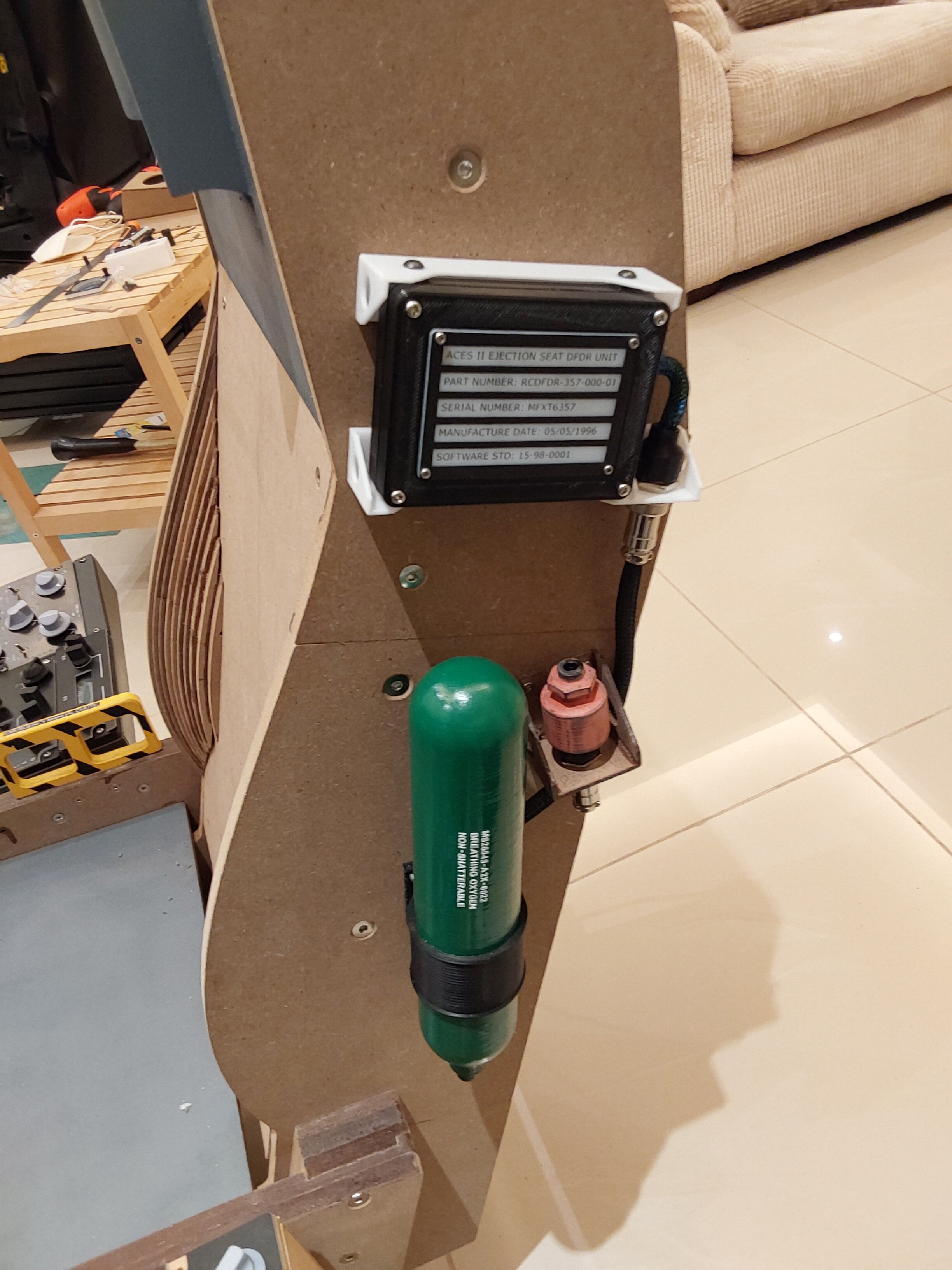
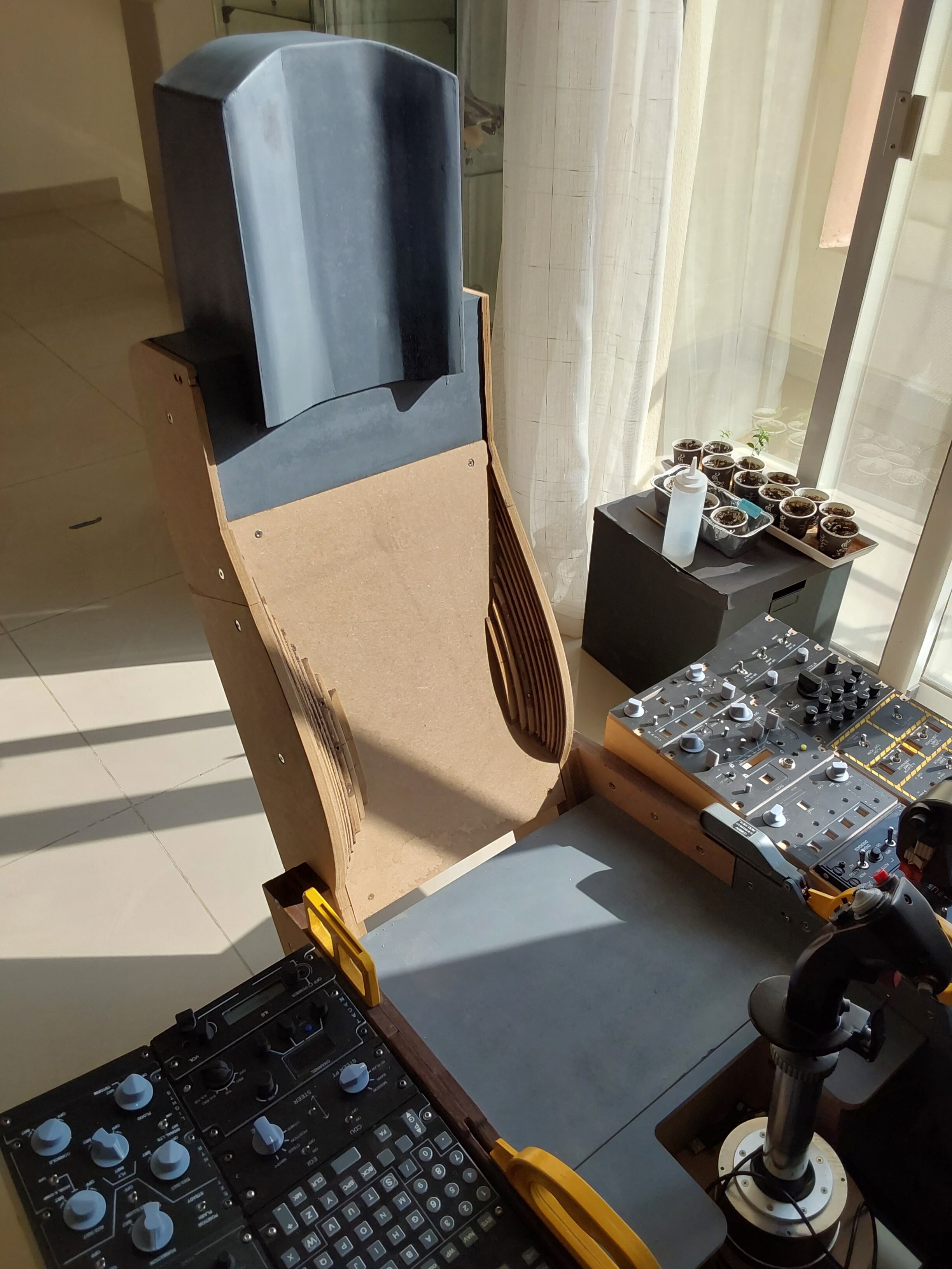
A couple more dress parts, basically to tart up the seat, and a revised standby attitude indicator to match some new hardware in the post. The DFDR data plate is a work of pure fiction, just to give some visual interest. If I manage to find a picture of a real one I'll probably update it The back of the seat is also just a vague representation of the real thing so that the back of the seat doesn't look so empty; there's no other real function to it! Cheers Les
-
I'm not aware of any; having said that I am happy to share my design which uses 3D printed parts and some simple 2D parts and cheapo bits off Ebay Les
-
This is a tactic I have seen used to do PCB masking too, although for me it hasn't been too successful. There is a version using laser printed designs on paper that you can transfer using acetone onto PCB's, but not sure how it would work for other media Les
-
Hi again all I have a load of 3D files I used to create bits of my rig, and have uploaded them onto GrabCad as it seems a bit of a waste not to. While they were designed specifically for my own rig and are entirely my own designs to fit the other parts I made, I have tried to make them look right. They may be of use to anyone looking to make their own parts, at least as a starting point https://grabcad.com/library/miscellaneous-3d-files-for-a10c-cockpit-parts-for-dcs-world-1 I do have the editable solidworks files for them too in case anyone wants them, let me know I have more bits and pieces that I will add to the site as I find them Cheers Les
-
Thanks - I did try a similar smoothing attempt, although it wasn't the code you used above. My attempt certainly didn't make any difference, though it's certainly worth trying your code Cheers Les
-
Circuit breaker panel and trims, plus a bit more work on the seat decoration Les
-
All, here are the rehashed files, hope they help someone! I added the following text to the page where the models can be downloaded so hopefully you can make these suit more easily "Re-done A10C knobs for DCS world based cockpits, some are .sldprt models that can be scaled without affecting the splined or D shaft attachment, the others .stl files. I have tried to provide different sizes on some to help compatibility These also differ from the previous ones in that the geometry of the shaft fitting feature has been changed to make it easier to get them to suit as there is a shorter spline with a relief behind to allow you to fettle the feature more easily. if you find they are too slack on the splined shaft, I found that putting a little UV cure resin into the spline with a brush, part curing with sunlight or a UV torch and then pushing the spline into position allows a snug fit. You can then cure the resin fully in the spline. If they are too tight, I used a splined multi position switch with a metal splined shaft as a broaching tool. All you do is file the end of the shaft so the spline edges are sharp, and you can use it as a simple cutting tool by pushing it into the splined hole until it cuts the resin sufficiently to give a good fit" https://grabcad.com/library/a10c-knobs-for-dcs-world-based-cockpits-1 Les
-
Thanks - no gauges or analogue devices on the left console so at least that simplifies things there. Now you mentioned it, I remember that having an OLED display plus a guage running from a nano resulted in huge lag, basically made it unworkable. As for the servo operated device, I may try that to see if it helps with the movement of the pointer for a couple of the gauges. Most don't move much when in operation, but some are more dynamic and I was always less than happy at the rather jerky movement. Maybe this is a way round it Cheers Les
-
A bit of progress, some work on the seat and other bits and bobs. Most of it is a combination of 3d printed parts, some on a Lulzbot Mini, some on an Anycubic Photon Mono X. The major work with these was the post print surface prep, in order to hide the very visible layers on the FDM printed parts, but once done they look the part. Painting will follow once I'm happy with the finish. For the seat itself, the bolsters on the seat back will be filled with car filler and sanded to the correct contour using the MDF formers as a guide. The undercarriage lever assembly was virtually a drop fit and is a vast improvement on the first one, and I was able to recycle the old one for duty as the refuelling door lever. I have started using magnets to give some feel to some of the parts, which helps them feel less toy like in their action. It's quite surprising how much difference a couple of tiny magnets make. I'm still waiting on some Ebay parts to arrive to complete a number of the left console panels, OLED panels and some rotary encoders are still in the post
-
Great, thanks! I'm hoping to be able to rationalise the devices to cut down on the sheer volume and numbers of wires, and in time go back to the ones I did on the right console to improve that. As you go further along with all this, you look back and realise that what seemed a good solution at the time is actually a long way from ideal, with the result that sometimes it takes me a while to work out how I wired something up. It didn't help when I had that period during which the RS485 network refused to work and let me to make some fundamental changes to the design process; now I can correct that Vinc has indicated a rather nice setup for the digital clock and standby attitude indicator using ESP32 devices, but apparently they do not support RS485. If I end up using it (very likely considering how good it looks) then I will need to use USB so anything that can be pushed to RS485 will help free up resources. When I used just USB for all the gauges the lag and data refresh speed was appalling Cheers Les
-
Yes, basically it would good to know what can be used as slaves so that I can optimise the use of them. The more powerful arduinos can be used for multiple devices and inputs, but clearly if they can't be used as slaves it renders them useless. I have some unos and a couple of megas in my box of bits Cheers Les
-
All, I've asked this question before in a thread but want to try and get an answer Is there any way of recording the DCS-Bios output data so that it can be used to diagnose issues for gauges and lights etc? It seems that analogue type outputs, particularly for fast moving gauges is not a smoothed output, resulting in less than smooth gauge movement. However since I can't look at the data offline, I am only assuming that it is so If the data could be recorded and exported to the likes of excel, it would be easy to see how the data plots, which would help in understanding it Cheers Les
-
All, looking at my rig, most of the left console could be done either with a bodnar board or Arduinos. There are some OLED panels and the BCD switches that will need Arduinos though, so i was looking at using a Mega to drive all of it. I believe that Megas can be used as slaves on an RS485 network. However there would be quite a few connections to make and it would be tricky to make tidy wiring for all of it to connect to just one mega. It would be impossible for me to make one PCB for all of it, I think the best I could do would be three, with one Arduino on each Maybe three Uno boards would be better but I am not sure whether they can be used as slaves. They have enough pin connections to be able to do the job and drive the OLEDs but there's no point if they can't be used as slaves for the RS485 network So where can I find a list for compatibility for using as RS485 slaves so I can select the right Arduino? Cheers Les
-
Thanks, as it happens I found a place in the Souq Waqif that sold materials for sun shade and outdoor furniture. They had some faded olive green canvas that will do the job at least temporarily Cheers Les
-
All, I have an updated set of files for the different knobs and switches, including some that were not there before. They are available both as .stl and .sldprt files, and with the latter many have the ability to scale the knob without affecting either the splined or in a couple of cases D shaft fitting I'll upload to Grabcad and post the link here when done Les
-
I use stepper motors and drivers, controlled by Arduinos Take a look at this There are other posts I have made on this, but the most reliable setup so far has been A4988 drivers and X27-68 steppers, using Nano's to control. My only caveat is that the way that DCS-BIOS seems to output the data used by the Arduino leads to slightly jerky gauge movement Les
-
Yes, they do, which is a lot easier to do than i ever thought. The problem is making neat wiring, even if you are able to make PCB's I'm a bit pushed for time right now but tomorrow will give you details. Anything in particular you want? I got all my knowledge (ok, nearly all) from the very kind and helpful people in these forums so i am totally happy to share any info I can give you, plus I have dedicated many posts to my attempts to make everything work including the RS485 network. Other knowledge was found on other sites but I have to warn you that there are some very clever but awfully impatient and unempathetic people on some of the so-called 'help' forums....! Cheers Les
-
Nice - does it include toe brakes on your DIY rig? I'm torn as to what to do, but it isn't very high on the (long) list of things to do so I have time. If I had access to better machining facilities I'd probably go for a complete scratch design usinga Bodnar board but at the moment that is not possible. One of the questions I have is whether to have them as sliding pedals or pivoted, which would be simpler to implement. The problem with the pivoting type is the toe brakes, it's possible but does complicate things Cheers Les
-
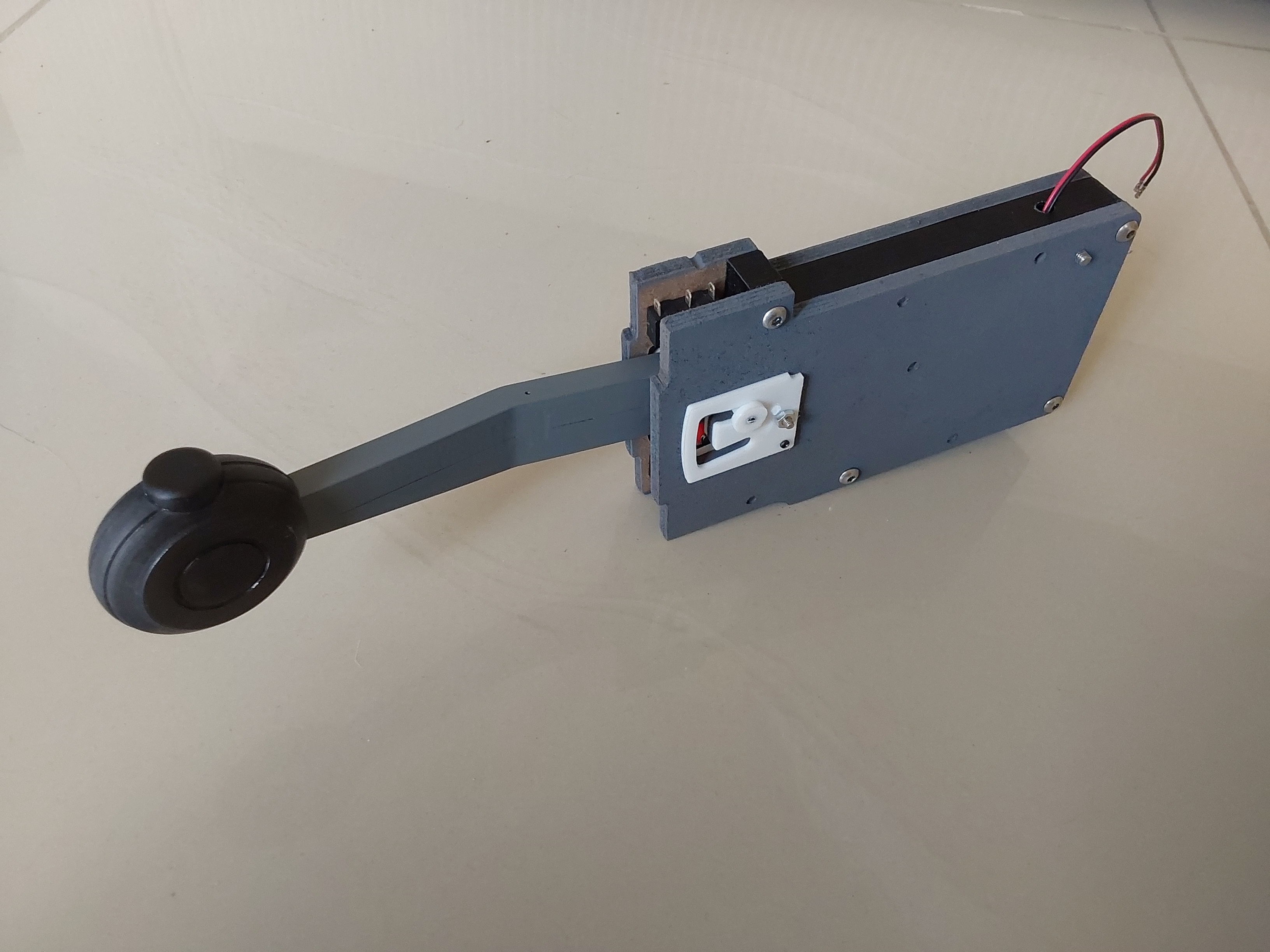
Finished the proper undercarriage lever mechanism finally, works really nicely after quite a bit of fiddling and fitting Cheers Les