lesthegrngo
-
Posts
1245 -
Joined
-
Last visited
Content Type
Profiles
Forums
Events
Everything posted by lesthegrngo
-
I'm happy to limit to a reasonable number of inputs per Nano, simply based on the fact that I'd need around 40 total for all the inputs plus the Bodnar boards Cheers Les
-
Help requested geting a sketch to run with RS485
lesthegrngo replied to lesthegrngo's topic in Home Cockpits
I have a knock on question, more for my information than a search for a solution I found that via USB, I could quite easily drive three stepper motors at any time, for example APU Temp, APU Revs and Eng 1 Fuel Flow would all display perfectly via USB. Once the sketch was converted to RS485 it was no longer able to deal with more than one stepper, as even two would just end up with random movement. I'm fine with one Nano per stepper as it would be how it was originally (and I'm amazed at how much more reliable it is) but am curious as to why there is a difference when connected to RS485 If anyone can offer any insight I would love to know why Les -
*****EDIT**** Found the issue, one of the first PCB's I made and it has pins A & B transposed on one of the RS485 inputs Thanks for anyone who looked at this, sorry to have been a nuisance Hi all, in an attempt to get away from using EasyDriver boards, which have at least in my experience been very prone to blowing and super sensitive, I have developed the following sketch to drive the X27-168 stepper motors direct from the Nano boards. The advantages are that a) I avoid using the EasyDriver boards and b) I can still use the existing PCB's I have by just adding some jumpers to connect direct to the stepper from the Nano. The sketch below works fantastically via USB, reliably and while simple will hopefully serve as the basis for improving some other parts. However when I comment out the "#define DCSBIOS_DEFAULT_SERIAL" and uncomment the " #define DCSBIOS_RS485_SLAVE 33 /#define TXENABLE_PIN 2" I then have no success in getting it to work with RS485. I am checking that RS485 is active using another RS485 connected device, so can demonstrate that RS485 is working. here is the full sketch #define DCSBIOS_DEFAULT_SERIAL //#define DCSBIOS_RS485_SLAVE 33 //#define TXENABLE_PIN 2 #include "DcsBios.h" #include "SwitecX25.h" // 315 degrees of range = 315x3 steps = 945 steps int newValue; unsigned int maxSteps = 800; // declare motor1 with 945 steps on pins //SwitecX25 motor1(maxSteps, 9, 8, 10, 11); SwitecX25 motor1(maxSteps, 6, 5, 7, 8); void setup(void) { DcsBios::setup(); motor1.zero(); // this is a slow, blocking operation motor1.setPosition(500); } void onApuTempChange(unsigned int newValue) { unsigned int position = map(newValue, 0, 65535, 0, maxSteps); motor1.setPosition(position); } DcsBios::IntegerBuffer apuTempBuffer(0x10c0, 0xffff, 0, onApuTempChange); void loop(void) { motor1.update(); DcsBios::loop(); } Can anyone see why this would not work with RS485? I will try and splice in the stepper initialisation and configurations that are used in other stepper sketches one I work this out wrinkle Cheers Les
-
How weird is this - it only works if I have a specific USB stick plugged in, even though the .json files are in the debug program root folder on the c drive. If you take the USB drive out, it stops working The drive was not used to install the program or save any profiles, and has no DCS Bios info I used Ccleaner to clear the registry but no difference. I better not lose that USB stick…. crazy!
-
Hi guys, this has suddenly stopped working - when you open it it shows the CMD screen, then shuts off Anyone seen this? Cheers Les
-
You know those moments when you look at something you made and think to yourself "what on earth was I doing...?" Les
-
Cool, thanks - I knew there must have been a reason, serves me right for not documenting all this stuff at the time. Part of my rationalisation of all this is that I will be making better notes of what I am doing, the amount of time I have wasted covering ground I had already covered before is astounding. Pinout diagrams, logic charts to show how stuff is all connected together, properly annotated PCB diagrams.... Lots of work to do Cheers Les
-
This tidy up that I am doing is throwing into sharp relief a load of issues that are of my own making - talk about going down a rabbit hole.... One of the things I was doing was trying to assign as many minor functions to Nanos that are used for the 'bigger' devices. A good example of this is where I have a Nano driving all three CMSC LCD displays, via I2C driven PCF8574 boards that have assignable addresses. I was very pleased with myself at the time at getting this to work nicely. However the I2C connection takes up only 2 pins, leaving 14 pins for switch, encoder and LED connections. I want to use those to offload other devices, the CSMC does not update that frequently so putting the extra switches and LED's on it won't make any difference to the functioning Except that when I went to the hardware, the I2C connection is set to pins A4 and A5, and I can't for the life of me work out a) why those pins and b) where did I set them in the sketch? I supect that the answer is that they are preset somewhere else, but because of my processes at the time, I have no documentation to back up what I did, so I am having to relearn all of this to understand what I have already done. If someone can point out why pins A4 & A5 are seleted and where that is set I would appreciate it, but also can you advise whether I should be leaving A6 and A7 unused? Cheers Les
-
I (hopefully) will be using RS485 so shouldn't be an issue - but I appreciate the heads up Les
-
Thanks Vinc! Les
-
Guys, just revisiting this for some PCB tidying up Can you confirm on a Nano what pins can be used reliably for the LED outputs from DCS bios? I think it is D3 through D12 and pins A0 to A5, correct? Cheers Les
-
Hi, we had some discussion about this a while back- check out As ever, some really good feedback from the guys on the forum in it Cheers Les
-
Issue with Rotary Switches in F/A-18C Hornet Cockpit
lesthegrngo replied to hrnet940's topic in Home Cockpits
Can you post a picture of the actual rotary switch? If they are like the ones I have, instead of being a 12 position switch they are just four pole three position switches. To explan, when you turn the switch in links position 1, then 2, then 3, then 1, then 2, 3, 1, 2, 3, 1, 2, 3 I modified mine so now they are proper 12 position switches Les -
Not enough HDMI outputs on Graphics card
lesthegrngo replied to lesthegrngo's topic in Home Cockpits
Nice, thanks for sharing! Les -
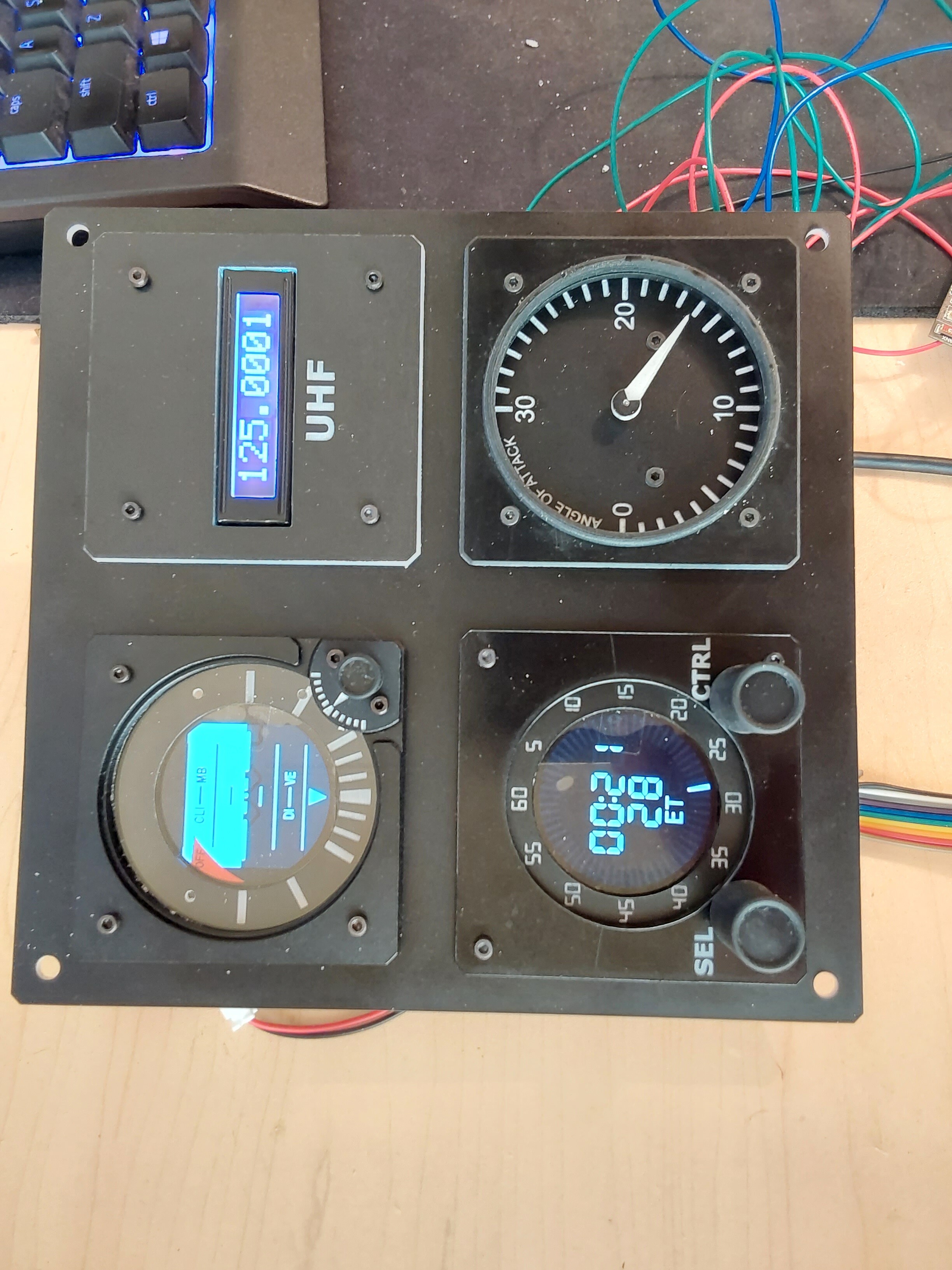
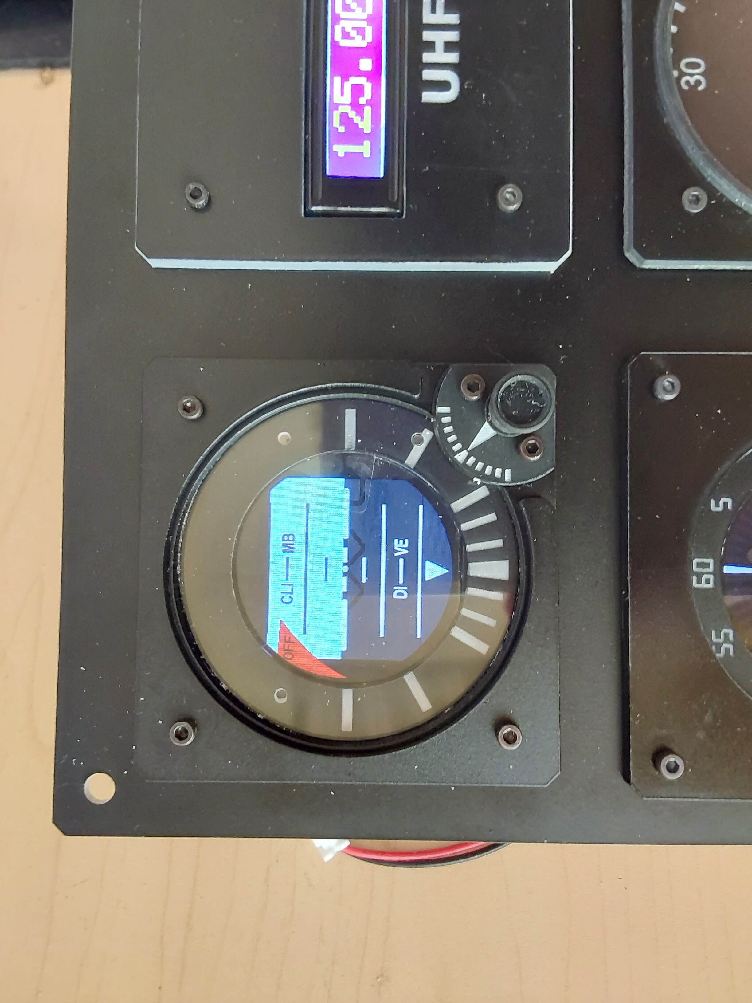
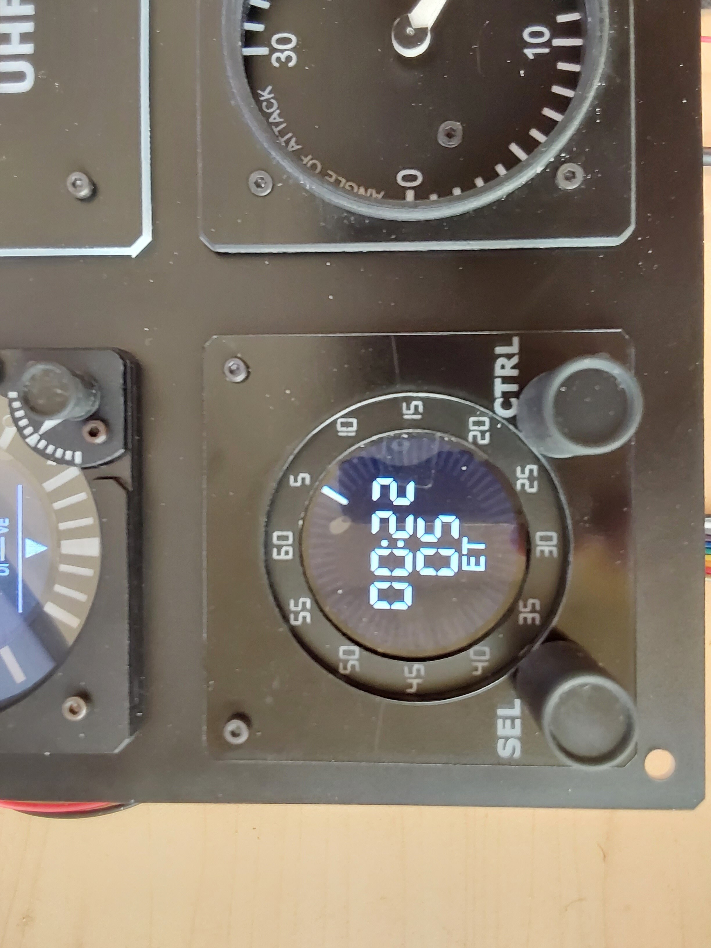
With the continued help of Vinc Vega (and a lot of patience by him too!) I have finally got my standby instrment panel finished. The clock and the SAI look fantastic I still have to make the new AOA gauge glass as the old one is too small for the new panel, but that is a minor detail. For info, the picture makes the light areas a lot more blue than they are in real life Cheers Les

-
Not enough HDMI outputs on Graphics card
lesthegrngo replied to lesthegrngo's topic in Home Cockpits
Wow, that's great - most of the displays would not have any noticeable difference even at a quarter of the framerate; Maybe the moving map and the ADI / ASI would need full rates though Les -
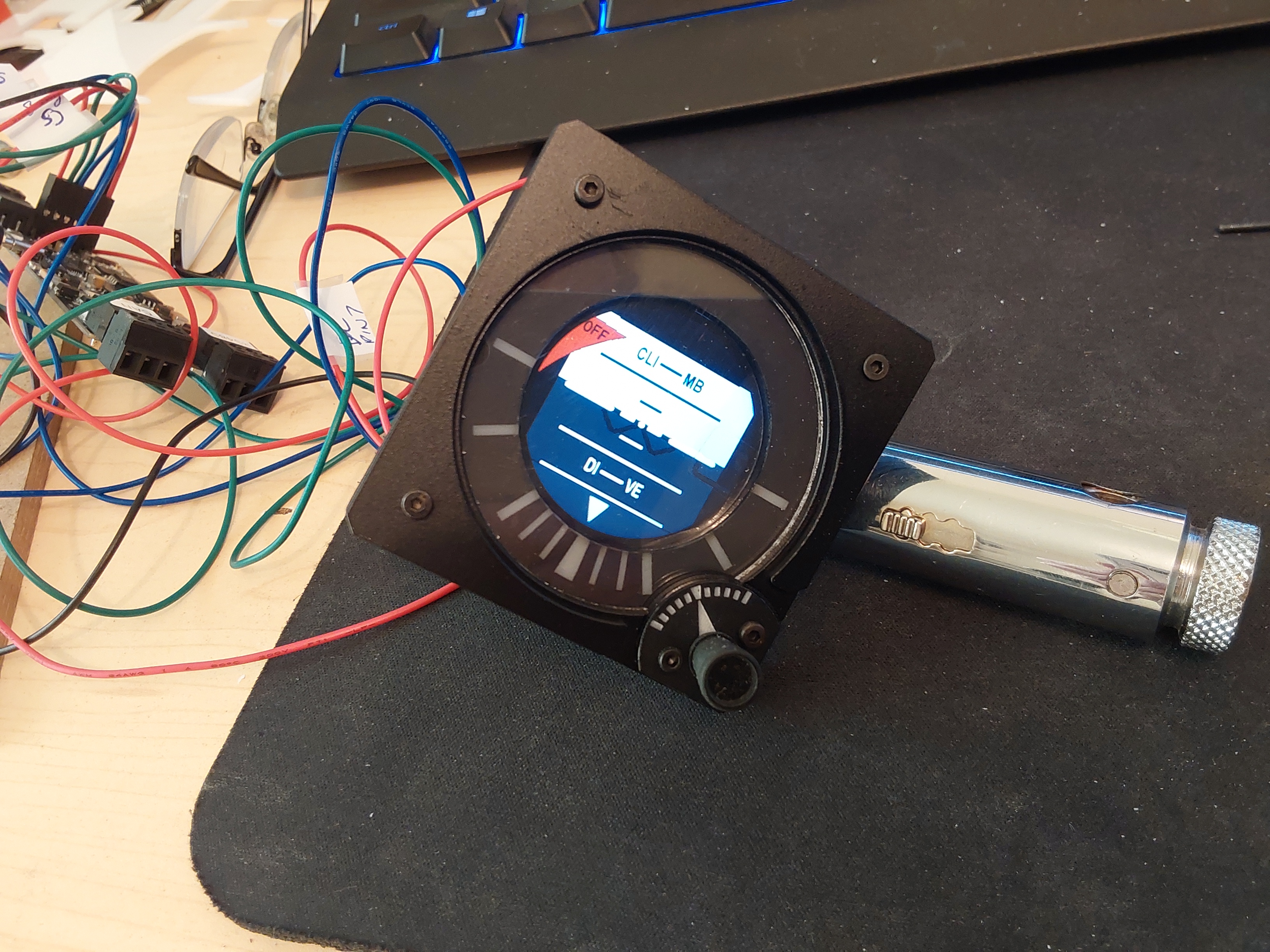
With a huge amount of help from Vinc Vega, I finally have a 'proper' standby attitude indicator; the software and electronics development was entirely his, and he's also been very patient in helping me get my (slightly different) hardware working. I then did the easy bit, which was to make a suitable instrument surround to show it off properly It works correctly in game and has functionality built in that so far I haven't tested, but I will get round to it By the way, for a sense of scale the allen bolts are M2 Cheers
-
Not enough HDMI outputs on Graphics card
lesthegrngo replied to lesthegrngo's topic in Home Cockpits
"So, there is a non-trivial increase in CPU usage associated with these adaptors (which I expected) but it can be considerably reduced by rendering cockpit displays every other frame" interesting, where do you select that? Cheers Les -
I like Bodnar boards because they seem to be light on resources and are uber reliable. My problem is that I have four BBI-64 boards already to run the switches and encoders I have. There is a way of making a matrix for the switches that increases the number one board can handle, but not sure that allows use with encoders. Last time I checked (admittedly a while back) Bodnar didn't sell a matrix board but if they did I would be tempted. The invariable downside is the plates of spaghetti trying to get everything connected to it! As for Vinc's suggestion of expanders, I'll have to check it out as I'm unfamiliar with them. As ever, I'm so impressed by the great info and feedback I get when asking my daft questions; always worth asking here! Cheers Les
-
Paid for DLC not available in offline mode
lesthegrngo replied to lesthegrngo's topic in Installation Problems
Thanks, will take a look Les -
Hi all I have just gone to DCS world to work with the DCS Bios setup for an input / output device, and it is asking me to login to the Multiplayer part, which I don't want as I need to do some testing offline. However when I do that, my DSC A10-C DLC is now disabled, even though it was purchased as a standalone DVD copy. It never used to be like that, and why should it matter if I want to play something I paid for offline? Can anyone advise as to how I can rectify this? Cheers Les
-
At the risk of complicating this question, I realise that I inadvertently left out one important part of this. Is it better (less laggy, less demand on the system, less complicated etc) to have inputs via RS485 where possible rather than use Bodnar boards? They use USB, and I just assumed that the less reliance on USB the better, although the Bodnar boards rate very highly in my experience. I know that when I tried to drive all the Nanos via USB it was terrible and slow, does increasing the reliance on RS485 do the same? Cheers Les
-
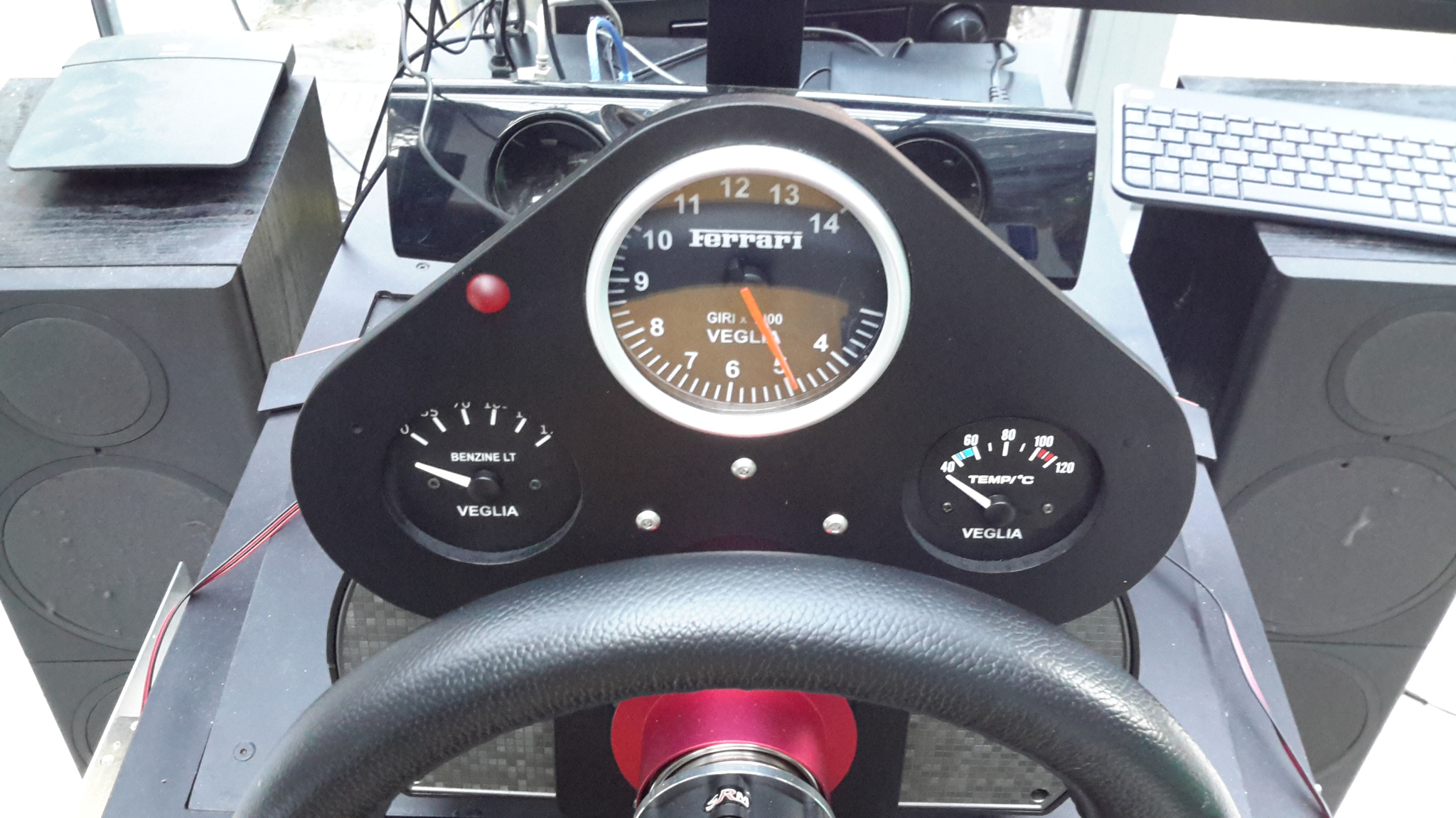
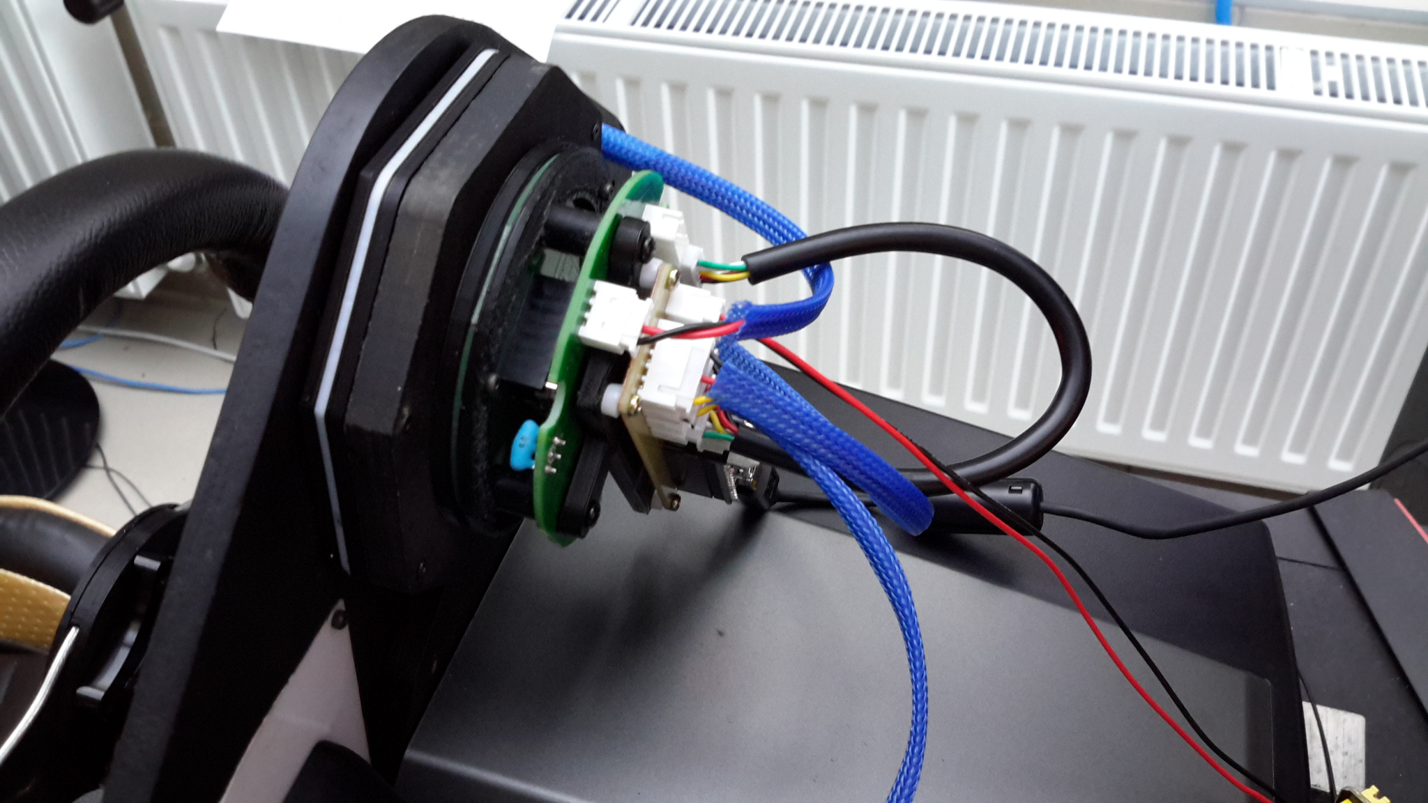
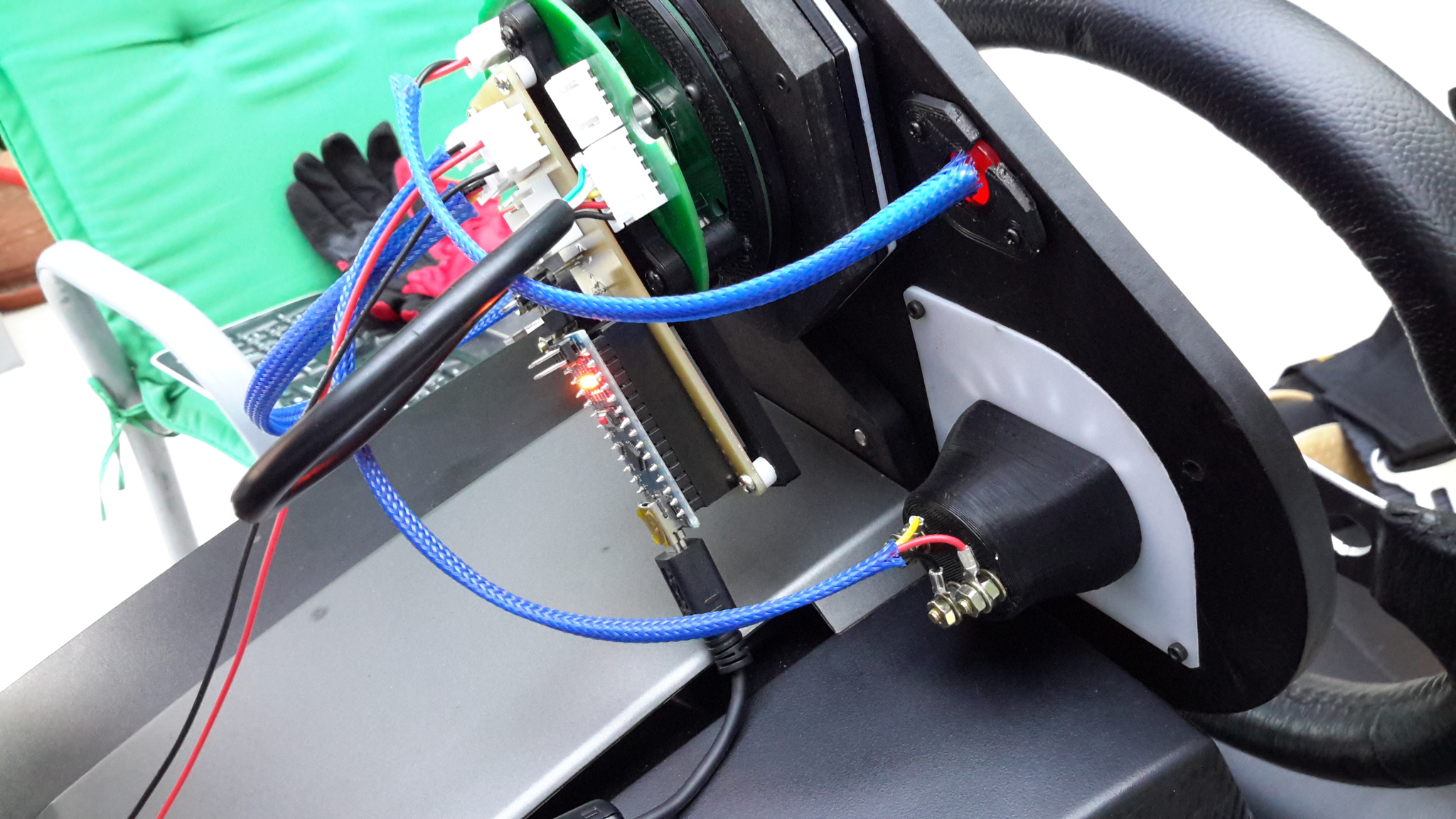
I've been meaning to ask this for a while now, originally as part of my attempts to get round the fact that I couldn't resolve the issues that plagued my RS485 setup. It looked like I would have to use Bodnar boards for switches and encoders as much as possible and connect via USB all the arduinos etc necessary to run the gauges / LED's etc. Thankfully the RS485 issues were resolved (it was down to a corrupted Arduino IDE installation) so I'm back on track. However I do want to rationalise as much as possible, as clearly the lower the number of devices the simpler the pyhsical setup will be, obviously at the expense of the programming. So, assuming that I have an Arduino Nano allocated to a particular gauge stepper motor, that leaves a number of unsused pins that could be used for switches, LED's, encoders or potentiometers. Leaving aside the outputs for LED's, as there aren't that many as they require a voltage output / pin to ground, how many of the remaining pins can be realistically used for switch, encoder or Pot inputs for DCS BIOS? As I see it I have the following pins that can be used, two of which will be given over to stepper STEP and DIR outputs to the stepper driver A0, A1, A2, A3, A4, A5, A6, A7 D2, D3, D4, D5, D6, D7, D8, D9, D10, D11, D12, D13 I built a Ferrari 312T4 'dash' to go with my racing Sim a while back (photos below) that used an Arduino to drive some gauges and a stepper motor, and while the schematics stated I could use any of the D pins for the PWM output / input of the devices, I found that it was not the case. The only PWM capable pins are 3, 5, 6, 9, 10 & 11. Using other pins can cause problems, and I also found that pin 3 could not be made to work no matter what, showing it was not as simple as it first looked. So assuming switches, encoders and Pots all have GND connections, what pins can I reliably use for them? Is there a limit in terms of which pins encoders and Pots can be connected to? And is there a limit to the number of switches that can be connected before it causes issues? Cheers Les
-
Not enough HDMI outputs on Graphics card
lesthegrngo replied to lesthegrngo's topic in Home Cockpits
Yep, found it on Amazon UK, there's a 4K capable and a non 4K capable one. For the small difference in cost I'll go for the 4K capable one in case it becomes necessary. I'll get my son to bring it out at Crimbo time. I will plug it into the MOBO 3.0 port, but it's a C type connector, I assume that for this to work with the least lag it's best to get a good cable? I have no C type ports in my MOBO Les -
Not enough HDMI outputs on Graphics card
lesthegrngo replied to lesthegrngo's topic in Home Cockpits
Thanks, that looks exactly what I want. Searched on Amazon and that one didn't appear so need to see if any other seller will ship to Doha. Essentially I just need it for the four small (two 10", two 7") monifors on the dash, and that would also help with cable management So as far as I can see this runs off USB? No HDMI in? Cheers Les