lesthegrngo
-
Posts
1245 -
Joined
-
Last visited
Content Type
Profiles
Forums
Events
Everything posted by lesthegrngo
-
****edit as I realised that I did not state which aircraft!******* For the A10-C, i want to understand the way that some controls work This will probably be a recurring question for me, as I go around my rig gradually getting it nearer an imaginary finsihing line. There are a number of panels that I have made that in retrospect I have wrongly portrayed. This is because at the time I was making them with the resources I had available to me, for instance the knobs and switches commercially available, what I could design and manufacture due to the tools I had etc. Admittedly some have no function in game or at least are not important ones, but I'm sure a lot would agree that it's more satisfying when the details are right Now I have better resources, I can see bits and pieces that while for most intents and purposes are OK, they are wrong and somehow they have started to draw my attention out of proportion to their importance, and so at some point in the future I will go back and fix them. It will also allow me to simplify some things that I overcomplicated when I had no experience with Arduinos. Also, reference material has turned up that shows that I have some things wrong that I didn't know at the time. I also have to say that in a lot of cases I do not know how the real unit functions, so I just took a punt with what I thought at the time, so maybe used a rotary encoder or a rotary switch instead of a potentiometer. Lastly, with my AnyCubic Mono X printer I can now make really nice knobs and switches that match more closely the real ones Two panels are ones that I will start with are the Oxy panel and the environmental panel. On the Oxy panel, I have it as three mini toggle switches, but going back and studying the available pictures it looks like that from left to right, it should be:- either a three position toggle switch, or a three position rotary switch laid on its side (emergency, normal, test mask) a potentiometer (100% oxygen, normal oxygen) maybe a two position rotary switch? (On, off) Also, the shape of the switch levers seem to be a disc with a tab sticking out rather than a toggle lever For the environmental panel I have the following units connected via rotary encoders Canopy defog - potentiometer? Flow level - potentiometer? Temp level - potentiometer? At the moment due to the silly little knobs that I could get at the time all three of the above have tiny liitle knobs that are totally wrong in shape and size, despite my best effors so far, but if I am going to change it I want to do it all in one go - it would need a new fascia and possibly backplate to accomodate the correct size knobs So if anyone can confirm how these units should be protrayed I would be grateful, as in time I will go back and redo to assuage my OCD Cheers Les
-
Thanks guys This has taken a recent development as due to a windows update, my PC for some reason will not now recognise the second GPU (RTX660) as it keeps coming up with "driver not installed" errors. This halves the number of displays I can connect in a stroke so compromises my display of instruments. Even if there is no performance improvement it still may be a solution that helps me Cheers Les
-
I see, you changed it so it was more a "push pull" movement that a sliding type movement. Do you still use the toe brakes? Cheers Les
-
Thanks guys My models are a source of pleasure Was that to improve feel? I feel like mine are very wobbly, or at least not very positive Cheers Les

-
Thanks guys Never heard of Slaws or Crosswinds, will have to look them up! Cheers Les
-
A question for you guys out there. The Saitek pedals are not impressing me in terms of quality, feel and comfort. I'm tempted to try and use them as a basis for some more sturdy homebred ones, but want to know if anyone has tried modifying them and whether there is really scope for improvement. Sometimes you are really trying to polish a turd and would be better off with alternative hardware, but in the past I've managed to make some really good stuff out of what looked at first sight like rubbish. I don't want to waste time messing with them if there's no point Cheers Les
-
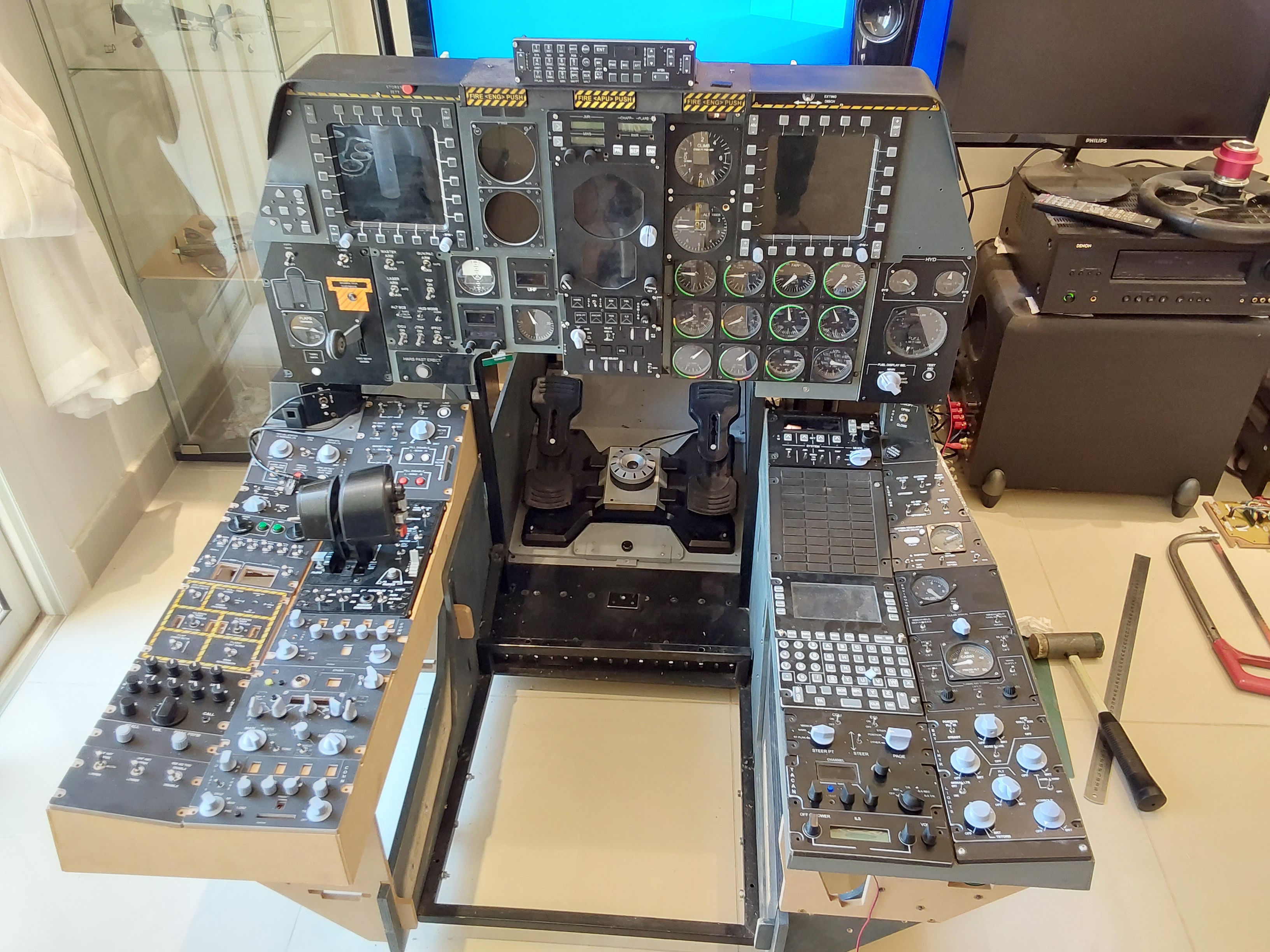
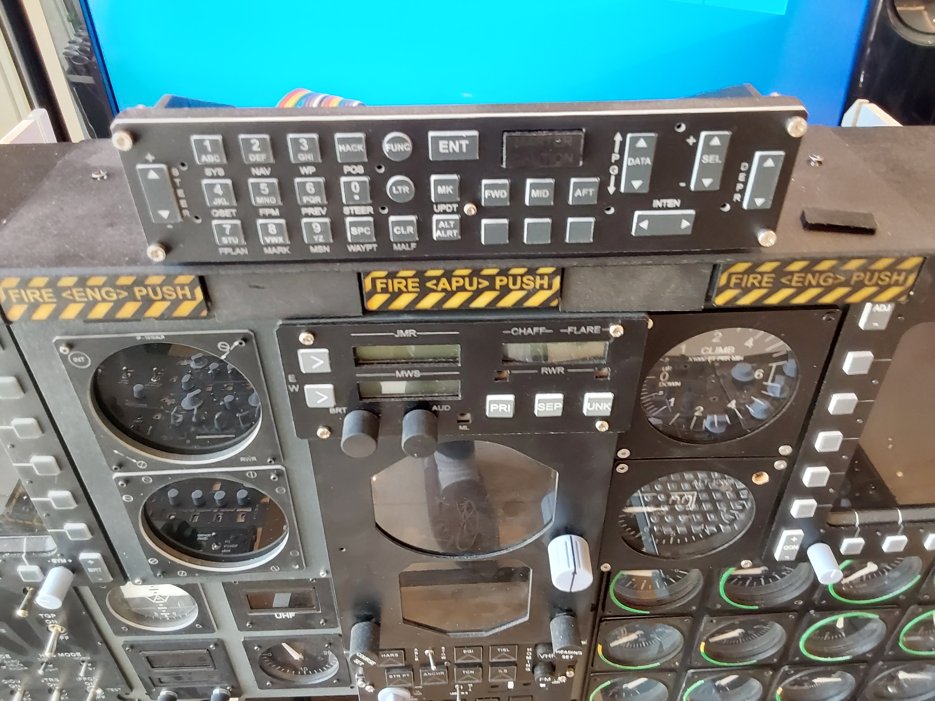
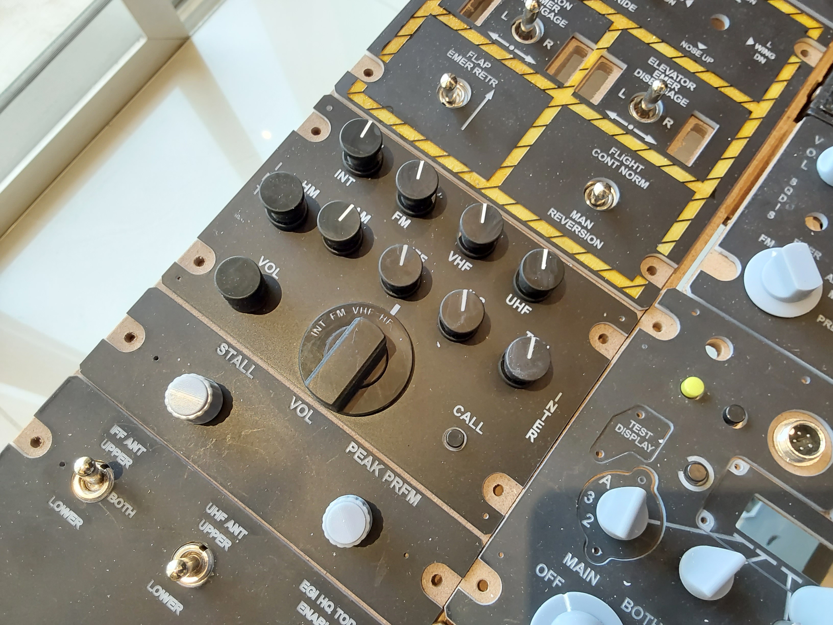
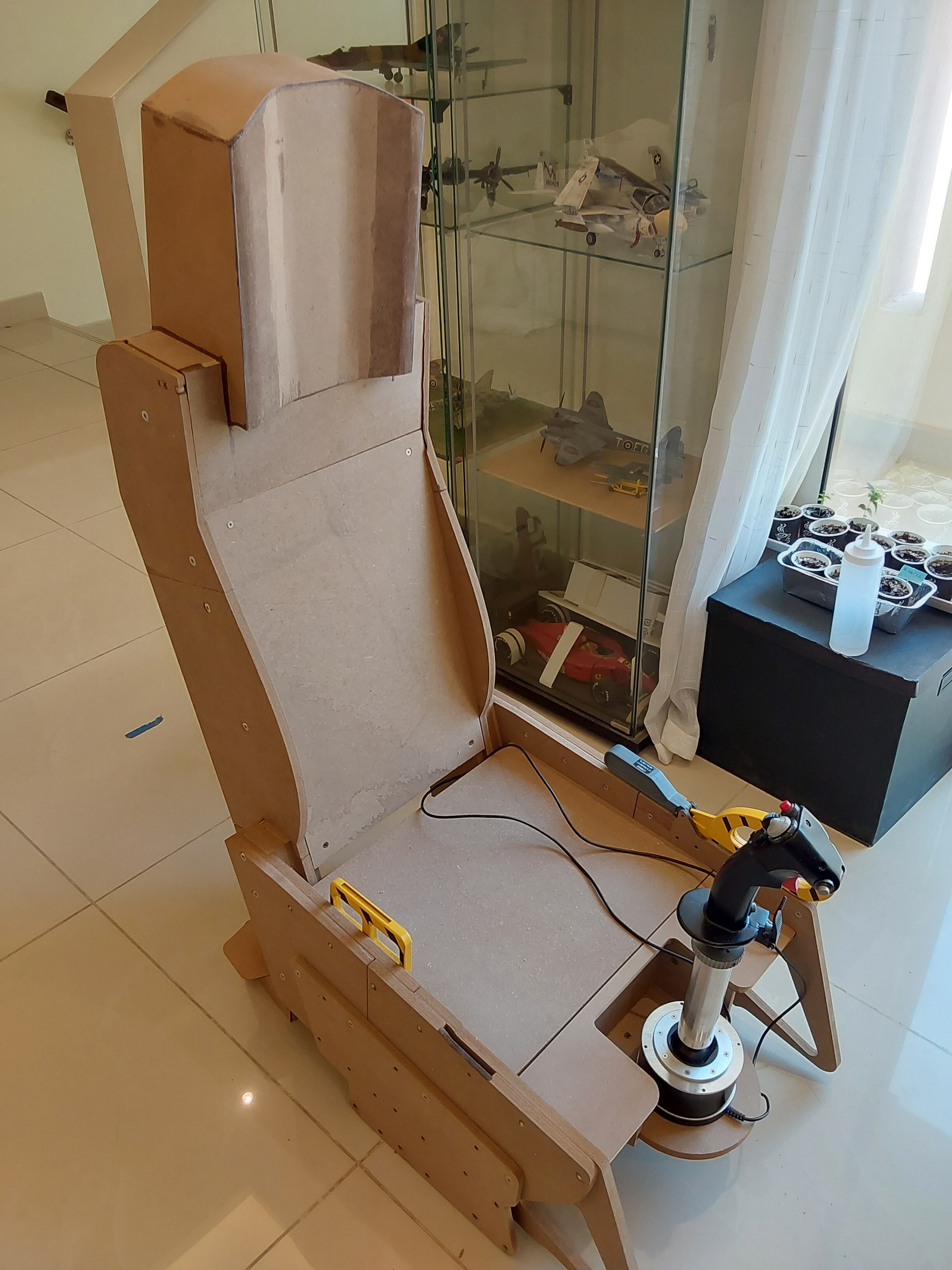
Hi all, it's been a while since I last posted some progress shots of my stand off A10 cockpit. I recently have regained a bit of momentum after the move, in which I nearly had all my stuff confiscated as the customs guys initially thought it was military stuff. Thankfully they accepted that real military hardware isn't made of MDF, acrylic and cheapo chinese electronics! Unfortunately my K40 laser machine blew the power supply, so I have been catching up on lots of little jobs, and also making a crude seat now I am able to have a dedicated racing sim rig. Unlike Hungary, MDF and acrylic are easy to find here, so after having luckily made all the fascias for the left console before the laser blew, I got on with the seat and console parts. At the moment I am just making dumb panels without lighting as most are not critical, but with time I will go back and update them. One thing I did spend some time on were the knobs, and I think they turned out really well considering. I changed the geometry of some and spent time making sure they fit correctly, meaning I have a load of spares. I'm waiting for some ebay bits and bobs so I can fully assemble some of them, bits that can't be sources locally. There are also some BCD thumbwheel units sitting on my father's sideboard that will eventually be brought out by a visitor, as some vendors can't ship here. Until they get here there will be a couple of unsightly holes in the IFF panel! The seat I decided to do as a vague copy of the ACES ll and again, MDF available here made that possible. As I only have a small CNC router it is made in small sections, but it has come out well enough for my purposes. I need to get the canvas for the seat sqab covers, not sure if that will end up being something that someone has to bring out too. There are still a couple of niggling bits that I want to improve along the way, like the Digital Clock and the standby attitude indicator. I also want to find green on black or white on black LCD 8x1 character displays for the CMSC as for some reason the standard LCD black on grey ones really grate! Anyway, this is as much for me to keep up my mojo as it is to show you guys! Hope you like it Les Some more images
-
it may be a universal seat frame - I can imagine it is not Airbus themselves who make it, it will be a supplier, so maybe this seat or parts of it is used in ATR's or some other aircraft. I know the BOM of one of our engines is absolutely identical between two airframes, despite having very different engine designations Les
-
Thanks - interesting to se the seat skeleton too Les
-
Thanks - has a fabric weight of 500 grammes per square metre, that helps a lot. Cheers Les
-
Yeah, that would be good - Qatar Airport Authority won't let me wander unaccompanied, let alone take any photos Cheers Les
-
Thanks - here in Qatar sheepskin might be a bit too warm! Cheers Les
-
All, just want to check, is the A10 ACES seat cushion material olive drab canvas? Also, any suggestions on the weight, or weave or however the correct term is? Cheers Les
-
ok, I thought he was referring generically. The cheapo e-bay on-off-on switches can be made to be three way switches though, may be a cheaper opltion! Cheers Les
-
I'll give you a partial answer - using on-off-on switches like the ones above, but with six terminals, you can make the into a three postion on-on-on switch by connecting them in a certain way. Take a look at th elink, it does work, I have used it on my rig https://forum.digikey.com/t/wiring-a-dpdt-switch-to-act-like-a-sp3t/924 Cheers Les
-
Thrustmaster Warthog Flightstick unwanted rotational movement
lesthegrngo replied to lesthegrngo's topic in Thrustmaster
Thanks guys - looks like a bit of investigation is in order I'm lucky in that I have some machining facilities, so potentially I may be able to replace worn parts with metal replacements, assuming that the unit lends itself to that. I will try and search the internet for teardown videos to see if that gives me any clues Cheers Les -
Hi all, I am hoping that someone can help me with an (admittedly minor) issue I have with my flightstick. I am pretty certain it is a recent issue, but I never looked for it before so maybe it has been there for a while. The issue is that the flightstick has a small amount of rotational movement centred around the axis of the handgrip. It is the same direction of movement as that you get when you twist the handgrip to simulate the yaw function on other sticks. Looking at it, I see the ball at the base is moving with it, so it is not due to a loose handgrip to base screw. Has anyone seen this before, and is this something that can be fixed? A search of the internet showed how to remove stiction but I can find no mention of this, and now I know it's there I can't help but notice it! Cheers Les
-
Yeah, that's the type of thing I was looking for - the only thing is that the smallest (6 way) says 1.8m long, seems a bit strange Back in the early 90's when I was young and still single (i.e. disposable cash) I had HiFi separates and used a similar thing to that to tidy up the plate of spaghetti at the back of the stereo rack. I think I found it in a hifi shop in Spain, don't remember seeing them anywhere else However now I know the designation of the plug type ( C13) so that will make an internet search easier Thanks again Cheers Les
-
Hi All in the past, when making a rig that has multiple 240V units connected, my solution has been to get a power bar extension, the ones with say six power sockets on it, then box that into the rig somewhere. It's crude and bulky but it works. However there must be better solutions out there that will allow me to have a single power input and some gangs of screwed or mini connectors / plugs that I can splice onto the power cables leading to the units. None have to handle significant power but I would like a small form factor solution that can be put somewhere convenient under or at the back of the rig that I can also connect through a master power switch. Can anyone point me to these types of things that are commercially available? Cheers Les
-
ExpressPCB advice sought for non rectangular boards
lesthegrngo replied to lesthegrngo's topic in Home Cockpits
Thanks! Let me look into that! Cheers Les -
ExpressPCB advice sought for non rectangular boards
lesthegrngo replied to lesthegrngo's topic in Home Cockpits
Thanks for all the input and feedback guys, much appreciated! So I started playing with KiCad yesterday, just testing it out on boards I have already made to practice. I imported the DXF of the board with the DXF traces on it just so I could see placement, then tried to insert a component. I found the 0805 LED's and started placing them, although I will have to work out how to turn off the snap to grid as it would not allow me to place exactly. Should be simple enough to figure out. However the next component I wanted to insert was a 3mm x 6mm x 2mm high 'tactile' SMD switch.... but it doesn't exist in the library. Curiously, despite them being really frequently used (for example remote control devices), Mouser don't list them in their catalogue when I tried to find out if it had another callout name. So knowing that they must be listed somewhere, is there an extended listing of components available somewhere to add to the library? Cheers Les -
ExpressPCB advice sought for non rectangular boards
lesthegrngo replied to lesthegrngo's topic in Home Cockpits
Cool, but I suspect that Solidworks is not supported! Anyway, I am watching some tutorials to see if I can pick it up, hopefully the tutorials are good ones Cheers Les -
ExpressPCB advice sought for non rectangular boards
lesthegrngo replied to lesthegrngo's topic in Home Cockpits
Thanks guys, never heard of KiCAD, will head over there right now - the ability to import .dxf files would be a massive help Cheers Les -
Hi all For a good while now I have been making PCB's myself for my panels, using a combination of etching and CNC engraving and cutting. It's great for one offs especially if they are small, and by and large my success rate is fairly high. My problems start when I want to make larger, more complicated PCB's that require finer traces and multiple vias, and double sided so that I can have traces that cross without jumpers. A great example is the MFCD switch PCB's which need to be populated with 28 SMD switches, 28 SMD LED's and two rotary encoders. It must also must have the centre cut out so that the LCD screen shows through, and the outer board profile is not a rectangle, as the two encoders sit on little wings at the bottom on either side. Finally, I need the power connections for the LED's and the 33 pin header for the output to the Bodnar board. I have them made, and working, but to produce two functioning PCB's was hard; the traces had to be so fine that sometimes they ended up (with my production techniques) either being cut or not fully isolating from the adjacent trace. I spent many hours on post production troubleshooting shorts and open circuits. Additionally getting the SMD devices soldered onto the pads was fraught, as there was not much space, and some ended up detaching duing the soldering process. So I looked into the PCB design programs with an eye to getting them made by the online PCB manufacturing companies - I assuse most are based in China or around that region of the world. In order to do so I need to learn programs like ExpressPCB or Fritzing, and have started looking at tutorials for the former. However one part of the process I still have not been able to grasp is when I have a specific PCB board shape I need to work with so that it fits into the mating parts, and that the switches and LED's are correctly located so that the pads for the components are in the right places. I use a combination of Solidworks and QCAD for designing the PCB's and baseplates, fascias etc, so what I want is to be able to use the .DXF diagram of the board that I know has all the right inner and outer profiles, mounting holes and the correct reference points for the devices so that I can then use ExpressPCB to design the board. This is what I don't seem to be able to find in any of the tutorials, they all seem to deal exclusively with how to populate a board with components, traces and vias, but without the constraints of dimensional requirements of a specific shape of board and datums. If anyone is able to point me towards a tutorial that explains how to do that, I would be extremely grateful I would also appreciate any feedback from anyone who had home designed PCB's made. Remember I am looking at small quantities of each one, and I know that the benefits of economies of scale will be lost. If you have had the company populate the board with SMD devices (LED's, switches) I would like to know what your thoughts on the quality were. Cheers Les
-
To confirm, this is how I have my dash displaying the RWR, artificial horizon and a couple of others. On the RWR I found I had to move it away from the main display part of the extended screen so that the parts of the RWR frame wouldn't intrude int the main screen Les