lesthegrngo
-
Posts
1245 -
Joined
-
Last visited
Content Type
Profiles
Forums
Events
Everything posted by lesthegrngo
-
I tried the LCD output check - the output is rock solid, so the issue must be with the sketch glitching. Not sure where the corruption is creeping in, both the altXXXftCntBuffer and altPressure2Buffer outputs are stable and smooth, but I still get the values jumping around. So something must be reading the data wrongly or erratically, but on the face of it it is a very simple sketch so I am reverting to my base state of puzzlement for this one. I am trying to use the map function as you suggested, and after checking out the reference material I tried to splice it into my LCD code, which you can see below. I clearly am missing out something though, I get the dreaded "'newValue' does not name a type" error #include <Wire.h> #include <LiquidCrystal_PCF8574.h> #define DCSBIOS_IRQ_SERIAL #include <DcsBios.h> LiquidCrystal_PCF8574 lcd(0x27); // set the LCD address to 0x27 for a 16 chars and 2 line display int show; unsigned char newValue; newValue = map(altPressure0BufferValue, 0, 65536, 0, 10);{ // 65536 would = 10, and should never occur{ lcd.setCursor(0, 0); lcd.print(newValue); } DcsBios::IntegerBuffer altPressure0Buffer(0x1086, 0xffff, 0, onAltPressure0Change); /*void onAltPressure1Change(unsigned int newValue) { lcd.setCursor(7, 0); lcd.print(newValue); } DcsBios::IntegerBuffer altPressure1Buffer(0x1088, 0xffff, 0, onAltPressure1Change); void onAltPressure2Change(unsigned int newValue) { lcd.setCursor(0, 1); lcd.print(newValue); } DcsBios::IntegerBuffer altPressure2Buffer(0x108a, 0xffff, 0, onAltPressure2Change); void onAltPressure3Change(unsigned int newValue) { lcd.setCursor(6, 1); lcd.print(newValue); } DcsBios::IntegerBuffer altPressure3Buffer(0x108c, 0xffff, 0, onAltPressure3Change); /* void onAlt10000ftCntChange(unsigned int newValue) { lcd.setCursor(0, 0); lcd.print(newValue); } DcsBios::IntegerBuffer alt10000ftCntBuffer(0x1080, 0xffff, 0, onAlt10000ftCntChange); void onAlt1000ftCntChange(unsigned int newValue) { lcd.setCursor(7, 0); lcd.print(newValue); } DcsBios::IntegerBuffer alt1000ftCntBuffer(0x1082, 0xffff, 0, onAlt1000ftCntChange); void onAlt100ftChange(unsigned int newValue) { lcd.setCursor(0, 1); lcd.print(newValue); } DcsBios::IntegerBuffer alt100ftBuffer(0x107e, 0xffff, 0, onAlt100ftChange); */ void setup() { lcd.begin(16, 2); lcd.clear(); DcsBios::setup(); } void loop() { DcsBios::loop(); lcd.setBacklight(255); } Cheers Les
-
The altimeter isn't hooked up yet, as I am waiting for an optocoupler for the zero function - in the current situation I think it will be a while, but plenty of other jobs to do so it won't be a problem. I'll rig up an LCD today and try it, that's what I did to figure out the TISL output so I'll just re-use that hardware. Also curious about the map function, I have nothing to lose by giving it a go if I can work out how to use it Cheers Les
-
Ok guys, I made a video - and of course the Baro Altimeter behaves itself perfectly in this one, however the altimeter readout does misbehave - check out about 30 seconds in, remember the aircraft is static at the end of the runway so neither value should change at all I've tried increasing and decreasing the delay time for the data refresh, and it doesn't seem to make any difference Cheers Les
-
I am starting to see this when the aircraft is static on the runway now - I will try and make a short video. However as the values are static on the ground, it make me wonder what is going on that the output is so unstable. Cheers Les
-
Apologies about the aircraft type, it's the A10-C. This is the exemplar code from DCS BIOS reference void onAltPressure0Change(unsigned int newValue) { /* your code here */ } DcsBios::IntegerBuffer altPressure0Buffer(0x1086, 0xffff, 0, onAltPressure0Change); I have to confess it's a little confusing that the output is a 0 to 65335 integer for these four numbers, as it is a digital display not a gauge, and other similar outputs like the TISL code wheel numbers are actually output as the numbers (0 to 9 in 0.5 increment steps or 0 to 19 in 1 increment steps). If the output was like that it would be a lot easier to handle, and less prone to jitter. Nonetheless we have what we have, and I am very grateful for it. I suppose to I have to ask why does the value get corrupted, as maybe understanding that will help. Also, is there a better way to convert the 0 to 65335 output to a single digit Cheers Les
-
Thanks for the response I did try a slower sampling rate. For the scrolling number, too slow and it fails to scroll, but with the barometric one, I even tried a half second interval - totally slow. Funnily enough on the ground it is stable, but in the air, not even half second sampling helps, no idea why As for the rest of the suggestions, you may have to help this old brain understand how to approach those The output from DCS BIOS is an integer between 0 and 65335 in each case, and the 'if' mapping is a way to convert it, but I suppose not the only way Cheers Les
-
Guys, was actually flying around today, testing all the bits and bobs out, generally very happy with everything, especially all the gauges working in concert! I've got a load of OLED's working nicely too, but the two that are on the altimeter, the main one that scrolls the first three digits and also the one that has the barometric preset four digit number are behaving less that perfectly. It's splitting hairs with the scrolling altimeter, but the left hand number blanks and jumps, like its receiving a jittery signal. It is plugged into a USB port on the PC at the moment, after moving it from a hub to see if it improved the signal, but no difference. As for the barometric height setting, that is all over the place - it starts off displaying perfectly, then after a while seems to become a random number generator. As above, it is plugged directly into a USB port on the PC , not a hub. The code for it is below, as you can see it is not a particularly complicated one. ** EDIT - forgot to mention, it is a number that does not change, it stays constant as long as you don't make any adjustment, making it more weird that it daces about #define DCSBIOS_DEFAULT_SERIAL #include <DcsBios.h> #include <Arduino.h> #include <U8g2lib.h> #include <Wire.h> U8G2_SSD1306_64X32_1F_F_HW_I2C u8g2(U8G2_R0, /* reset=*/ U8X8_PIN_NONE); char* displayString = "----"; // onDcsBiosWrite does not exist anymore, use Int16Buffers instead DcsBios::Int16Buffer altPressure0Buffer(0x1086); DcsBios::Int16Buffer altPressure1Buffer(0x1088); DcsBios::Int16Buffer altPressure2Buffer(0x108a); DcsBios::Int16Buffer altPressure3Buffer(0x108c); void setup() { u8g2.begin(); DcsBios::setup(); } void loop() { DcsBios::loop(); if (altPressure0Buffer.hasUpdatedData()) { displayString[3] = mapeo(altPressure0Buffer.getData()); } if (altPressure1Buffer.hasUpdatedData()) { displayString[2] = mapeo(altPressure1Buffer.getData()); } if (altPressure2Buffer.hasUpdatedData()) { displayString[1] = mapeo(altPressure2Buffer.getData()); } if (altPressure3Buffer.hasUpdatedData()) { displayString[0] = mapeo(altPressure3Buffer.getData()); } u8g2.clearBuffer(); u8g2.setFont(u8g2_font_fub20_tn ); //u8g2.setTextSize(1); u8g2.setCursor(0, 24); u8g2.print(displayString); u8g2.sendBuffer(); delay (100); } char mapeo(unsigned int valor){ if (valor < 6553) { return '0'; } if (valor < 13107) { return '1'; } if (valor < 19660) { return '2'; } if (valor < 26214) { return '3'; } if (valor < 32767) { return '4'; } if (valor < 39321) { return '5'; } if (valor < 45874) { return '6'; } if (valor < 52428) { return '7'; } if (valor < 58981) { return '8'; } return '9' ; } It is not critical to get these sorted, but they are details that do make a difference. If anyone is able to make some suggestions as to how to improve this, I would be very grateful! Cheers Les
-
TISL / Radio selector wheel display output
lesthegrngo replied to lesthegrngo's topic in Home Cockpits
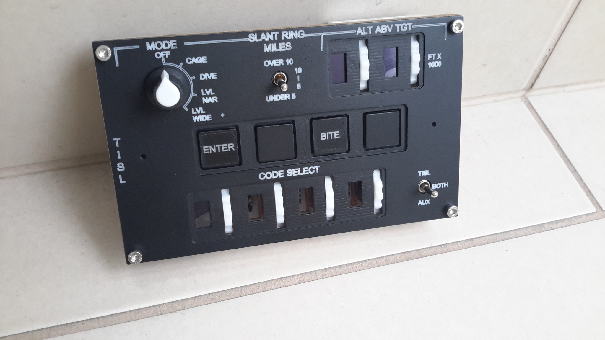
A quick update on this. As you can see my TISL lower panel is now basically finished, bar three 0.49" OLEDs needed to fill the gaps - they have been on order for a while, I don't think they'll be here any time soon in the current situation but that's fine. The TILS panel is not a replica of the real thing, I've used artistic license to make it fit my cockpit build, but I'm happy with it. The rotary encoders work nicely and the selector wheels are smooth in action so together with the OLEDs showing the half way numerals correctly I achieved what I set out for. It has been the most complicated item I've designed and built so far and in the grand scheme of things probably was not the best use of the time and effort considering how little it adds in game - but I have to confess I am really pleased at how it turned out. Next I need to turn my attention to using a TCA9548A multiplexer to allow me to make a sketch that enables me to control all 6 OLED's from one Nano, as the I2C addresses of these 0.49" OLEDs can't be changed. With any luck, due to the low refresh rate needed for this, I can run the six encoders, two toggle switches and the rotary switch off it too, but suspect I will be pin limited. Hope you like it Cheers Les
-
Pretty certain that there won't be an off the shelf sketch for testing it, however I wouldn't mind betting that there is an example sketch somewhere that uses one rotary encoder to light an LED or something that could be used - after all, as I understand it, the RE's just function as switches, so as long an you can change the input pin numbers in the sketch you can check them one by one. Once you know they all work, you can just allocate the pins to the input from DCS Bios This example here uses a stepper and LCD module to test https://howtomechatronics.com/tutorials/arduino/rotary-encoder-works-use-arduino/ Cheers Les
-
Thanks - I thought so too, as the pin number allocation for other sketches can be arbitrary Cheers Les
-
All, if I am going to use rotary encoders with DCS Bios through a Nano (or other arduino) board the common pin goes to the GND pin, but do the other two pins have to be on consecutive pins, or can they be assigned arbitrarily? On Bodnar boards they have to be adjacent pins, as the board has to be configured to accept encoders. Most of my inputs are via Bodnar boards but there are a couple of units (like the TISL I'm working on) that don't have configurable inputs in the controls setup screen so I have to go via DCS Bios. However it will complicate my PCB's if I have to ensure adjacent pins are used on the Arduino Cheers Les
-
***EDIT - just saw the 'make HTML' button on the assignment panel, that's done what I need ( I think) I assume that it lists all inputs** All, I have to connect all my cockpit controls that I have made to the game, and recently discovered some can only be accessed through DSC Bios, whereas a lot can be assigned via the game itself. I have to go through all of the controls to check which category they are in so that I can wire up accordingly and rewrite Arduino sketches as necessary. However to do this, I need a full list of what can be assigned in-game, and a Google search has not produced one. Faced with the rather unappetising prospect of actually sitting in front of the game rig and transcribing the control set up pages, I would like to know if there is either a full list out there (preferably excel) or a way of exporting the controls assignment lists from the game I want it for the A10-C (at the moment) but happy to receive info on any aircraft in case the madness spreads and I decide to do another cockpit Thanks Les
-
cool, great to hear you got it all working! Les
-
Hi there, can you send me the P51 .json file, then I can take a look using it and see if I can make a working sketch for you Cheers Les
-
TISL / Radio selector wheel display output
lesthegrngo replied to lesthegrngo's topic in Home Cockpits
I'm happy to report that due to the efforts of a long suffering guy over on the Arduino forum I now have this working. I need to tidy things up and make the definitive sketches and components, but we have another addition to the display sketches so that we can show individual click wheel windows Cheers Les -
For all you Arduino buffs out there, I need some help. I want to use the integer output from DCS as the pointer to an array, however I need to reference the newValue DCS output in the array callout string as you can see here unsigned char* aBitmaps[] = { c24_0, c24_1, c24_2, c24_3, c24_4, c24_5, c24_6, c24_7, c24_8, c24_9, c24_10, c24_11, c24_12, c24_13, c24_14, c24_15, c24_16, c24_17, c24_18, c24_19}; ; unsigned char* bitmap = aBitmaps[newValue]; However for some reason the newValue number is not being recognised and so no callout is made. If I replace the DSC newValue command with unsigned int = X it works If you guys can take a look and see if there is something obvious I'd appreciate it! Cheers Les
-
Inputs for controls not listed in assignment list
lesthegrngo replied to lesthegrngo's topic in Home Cockpits
Bummer! Ok, thanks Hans - just read what you wrote again and realised that the DCS BIOS input can be used, so actually in this instance I can. As you say, it depends on whether DCS-BIOS has it or not, and of course it means it has to go via an arduino rather than a button interface Thanks Les -
Guys, I am looking at the list of assignable controls and note that things like the TISL code wheels are not listed, despite the TISL codewheel outputs being output by DCS BIOS Is there any way to assign buttons and switches to these unlisted controls? Cheers Les
-
TISL / Radio selector wheel display output
lesthegrngo replied to lesthegrngo's topic in Home Cockpits
All, I have continued to make progress on this, with a new bitmap library for the digits and getting the display to work on those little 64 x 32 OLEDS using the U8G2 library, which seems to work better on these Using the test sketch below and the XBM.h library I made, I can individually call out the bitmaps pertaining to the different click wheel positions. So bitmap c24_3 for example will show you the bottom half of the 1 and the top half of the 2 Here's the test sketch, if you enter a number on the "u8g2.drawXBM( 0, 0, 64, 32, c24_XX);" line between 0 and 19 in place of the XX you will get the appropriate bitmap #include <Arduino.h> #include <U8g2lib.h> #include <Wire.h> #include <XBM.h> U8G2_SSD1306_64X32_1F_F_HW_I2C u8g2(U8G2_R0, /* reset=*/ U8X8_PIN_NONE); void setup() { u8g2.begin(); u8g2.clearBuffer(); u8g2.drawXBM( 0, 0, 64, 32, c24_19); u8g2.sendBuffer(); } void loop() { } But (there's always a but, isn't there!) what I need the sketch to do is to look up the 'value' parameter output by the following DCS BIOS command "void onTislCode1Change(unsigned int value) { DcsBios::IntegerBuffer tislCode1Buffer(0x1116, 0x1f00, 8, onTislCode1Change);" From testing I know that the output is an integer between 0 and 19, so logically if I put the bitmap names in an array like so "unsigned char* aBitmaps[] = { c24_0, c24_1, c24_2, c24_3, c24_4, c24_5, c24_6, c24_7, c24_8, c24_9, c24_10, c24_11, c24_12, c24_13, c24_14, c24_15, c24_16, c24_17, c24_18, c24_19};" in theory I can call up the bitmap from the array using the 'value' output integer created by the DCS BIOS code. So this is what the code looks like, but as you guessed something is wrong and I cannot get it to display anything #define DCSBIOS_DEFAULT_SERIAL #include <DcsBios.h> #include <Arduino.h> #include <U8g2lib.h> #include <Wire.h> #include "XBM.h" U8G2_SSD1306_64X32_1F_F_HW_I2C u8g2(U8G2_R0, /* reset=*/ U8X8_PIN_NONE); void onTislCode1Change(unsigned int value) { DcsBios::IntegerBuffer tislCode1Buffer(0x1116, 0x1f00, 8, onTislCode1Change); unsigned char* aBitmaps[] = { c24_0, c24_1, c24_2, c24_3, c24_4, c24_5, c24_6, c24_7, c24_8, c24_9, c24_10, c24_11, c24_12, c24_13, c24_14, c24_15, c24_16, c24_17, c24_18, c24_19}; unsigned char* bitmap = aBitmaps[value]; u8g2.clearBuffer(); u8g2.drawXBM( 0, 0, 64, 32, bitmap); u8g2.sendBuffer(); } void setup() { u8g2.begin(); DcsBios::setup(); } void loop() { DcsBios::loop(); } It compiles and loads fine, it just doesn't display anything So to test I wrote this sketch, where instead of referencing the DCS BIOS code output, value is set by a static unsigned int line. If you replace the number on that line with a number between 0 and 19, it looks up the correct bitmap in the array and displays it. #define DCSBIOS_DEFAULT_SERIAL #include <DcsBios.h> #include <Arduino.h> #include <U8g2lib.h> #include <Wire.h> #include "XBM.h" U8G2_SSD1306_64X32_1F_F_HW_I2C u8g2(U8G2_R0, /* reset=*/ U8X8_PIN_NONE); static unsigned int value = 7; /*void onTislCode1Change(unsigned int value) { DcsBios::IntegerBuffer tislCode1Buffer(0x1116, 0x1f00, 8, onTislCode1Change); */ void setup() { unsigned char* aBitmaps[] = { c24_0, c24_1, c24_2, c24_3, c24_4, c24_5, c24_6, c24_7, c24_8, c24_9, c24_10, c24_11, c24_12, c24_13, c24_14, c24_15, c24_16, c24_17, c24_18, c24_19}; unsigned char* bitmap = aBitmaps[value]; u8g2.begin(); u8g2.clearBuffer(); u8g2.drawXBM( 0, 0, 64, 32, bitmap); u8g2.sendBuffer(); DcsBios::setup(); } void loop() { DcsBios::loop(); } So clearly something is wrong with how the DCS BIOS output is being handled. The array function is working fine, but I am unable to get the DCS BIOS output to work with the commands If anyone can shed any light on this I would be very grateful (not to say relieved - this has been flummoxing me for a couple of weeks now) Cheers Les XBM.h.txt -
Hi Heling As far as I can tell, I replicated the schematics called out in Hansolos' great thread accurately. It may be an issue that is specific to the PC I am using, after all it is possible for stuff to have conflicts. I have stopped work on RS485 now that I have established a way of achieving what I need without it. I will need more USB connections than if I had an RS485 setup, but it will be a manageable number that I think will work fine. maybe it isn't everyone's ideal solution, but for me it is workable, plus I finally can take my brain off that cooker! Cheers Les
-
I got this working. The logic in the BIOS reference seemed the same as other gauges, so I set up a sketch that read the output and displayed it on the LCD screen, which confirmed a numerical output from 0 to 65535. That matched what I was seeing from other gauges I deleted everything and started completely from new with a new sketch, and now it behaves as it should. I don't know what I did wrong, because the sketch was accepted by IDE, but clearly there was a minor error in it somewhere. On to the next part of this Cheers Les
-
looks great! Les
-
All, as I am unable to make an RS485 network function for me, I have written this sketch to allow you to connect multiple stepper motors to one Arduino Mega2560 and connect via 1 USB connection. It will allow up to 23 stepper drivers to be driven, and as of today I have had 16 gauges running simultaneously (all 10 engine gauges, both APU gauges, both hydraulic gauges and both fuel quantity gauges) without any significant lag or slow down during the game. You will notice that the initial gauge self calibration part is significantly slower, but once that is finished the operation is good. I have found it to connect reliably and function reliably and repeatably. Each gauge can be individually calibrated (you can add additional gauges and stepperConfifg instances as required up to the max of 23) When used with EasyDriver stepper drivers it only requires 2 wires for each stepper driver, one for step and one for direction, as from my tests there is no need to connect the arduino 5v and GND, although a common GND may be desirable. The problem I find with EasyDriver boards is that in my experience they are fragile and don't handle loose connections , and they also tend to run worryingly hot, even with low power stepper motors like the X27-68's I used. Obviously you need a power supply for the stepper drivers, I used a 12v supply. For use with A4988 drivers, you will have to connect the Mega 5v and GND as well as the step and direction pins. You will also have to reduce the maxsteps value in the calibration down to something like 200 instead of circa 4000 for the EasyDriver boards. However the A4988s seem to be more reliable, come with heatsinks that keep them at a reasonable temperature and subjectively seem to deliver smoother control of the stepper motor. As with the EasyDrivers you will require a 12v power supply a well The code is below, and please note that I am no expert on this - I just kept at this until I got it working. However it does work #define DCSBIOS_IRQ_SERIAL #include <AccelStepper.h> #include "DcsBios.h" struct StepperConfig { unsigned int maxSteps; unsigned int acceleration; unsigned int maxSpeed; }; class Vid29Stepper : public DcsBios::Int16Buffer { private: AccelStepper& stepper; StepperConfig& stepperConfig; unsigned int (*map_function)(unsigned int); unsigned char initState; public: Vid29Stepper(unsigned int address, AccelStepper& stepper, StepperConfig& stepperConfig, unsigned int (*map_function)(unsigned int)) : Int16Buffer(address), stepper(stepper), stepperConfig(stepperConfig), map_function(map_function), initState(0) { } virtual void loop() { if (initState == 0) { // not initialized yet stepper.setMaxSpeed(stepperConfig.maxSpeed); stepper.setAcceleration(stepperConfig.acceleration); stepper.moveTo(-((long)stepperConfig.maxSteps)); initState = 1; } if (initState == 1) { // zeroing stepper.run(); if (stepper.currentPosition() <= -((long)stepperConfig.maxSteps)) { stepper.setCurrentPosition(0); initState = 2; stepper.moveTo(stepperConfig.maxSteps/2); } } if (initState == 2) { // running normally if (hasUpdatedData()) { unsigned int newPosition = map_function(getData()); newPosition = constrain(newPosition, 0, stepperConfig.maxSteps); stepper.moveTo(newPosition); } stepper.run(); } } }; /* define stepper parameters for each guage, calculate maxSteps number to suit gauge then call out rekevant stepperConfig instance against particular gauge */ struct StepperConfig stepperConfig01 = { 3900, // maxSteps 1000, // maxSpeed 1000 // acceleration }; struct StepperConfig stepperConfig02 = { 5000, // maxSteps 1000, // maxSpeed 1000 // acceleration }; struct StepperConfig stepperConfig03 = { 4350, // maxSteps 1000, // maxSpeed 1000 // acceleration }; struct StepperConfig stepperConfig04 = { 4790, // maxSteps 1000, // maxSpeed 1000 // acceleration }; struct StepperConfig stepperConfig05 = { 4240, // maxSteps 1000, // maxSpeed 1000 // acceleration }; struct StepperConfig stepperConfig06 = { 3900, // maxSteps 1000, // maxSpeed 1000 // acceleration }; struct StepperConfig stepperConfig07 = { 4194, // maxSteps 1000, // maxSpeed 1000 // acceleration }; // first named number is step and the second is direction // for standard Mega 2560 board I have tested pins 2 to 13 and 2 to 35, giving a total of 23 pin pairs AccelStepper stepper01(AccelStepper::DRIVER, 13, 12); AccelStepper stepper02(AccelStepper::DRIVER, 11, 10); AccelStepper stepper03(AccelStepper::DRIVER, 9, 8); AccelStepper stepper04(AccelStepper::DRIVER, 52, 50); AccelStepper stepper05(AccelStepper::DRIVER, 3, 2); AccelStepper stepper06(AccelStepper::DRIVER, 48, 46); AccelStepper stepper07(AccelStepper::DRIVER, 7, 6); AccelStepper stepper08(AccelStepper::DRIVER, 5, 4); AccelStepper stepper09(AccelStepper::DRIVER, 44, 42); AccelStepper stepper10(AccelStepper::DRIVER, 40, 38); AccelStepper stepper11(AccelStepper::DRIVER, 36, 34); AccelStepper stepper12(AccelStepper::DRIVER, 32, 30); Vid29Stepper lEngTempBuffer(0x10b4, stepper01, stepperConfig01, [](unsigned int newValue) -> unsigned int { return map(newValue, 0, 65535, 0, stepperConfig01.maxSteps); }); Vid29Stepper apuRpmBuffer(0x10be, stepper02, stepperConfig06, [](unsigned int newValue) -> unsigned int { return map(newValue, 0, 65535, 0, stepperConfig06.maxSteps); }); Vid29Stepper apuTempBuffer(0x10c0, stepper03, stepperConfig07, [](unsigned int newValue) -> unsigned int { return map(newValue, 0, 65535, 0, stepperConfig07.maxSteps); }); Vid29Stepper lEngCoreBuffer(0x10a8, stepper04, stepperConfig03, [](unsigned int newValue) -> unsigned int { return map(newValue, 0, 65535, 0, stepperConfig03.maxSteps); }); Vid29Stepper rEngCoreBuffer(0x10ac, stepper05, stepperConfig03, [](unsigned int newValue) -> unsigned int { return map(newValue, 0, 65535, 0, stepperConfig03.maxSteps); }); Vid29Stepper rEngTempBuffer(0x10b8, stepper06, stepperConfig01, [](unsigned int newValue) -> unsigned int { return map(newValue, 0, 65535, 0, stepperConfig01.maxSteps); }); Vid29Stepper lEngFanBuffer(0x10a2, stepper07, stepperConfig02, [](unsigned int newValue) -> unsigned int { return map(newValue, 0, 65535, 0, stepperConfig02.maxSteps); }); Vid29Stepper lEngFuelFlowBuffer(0x10ae, stepper08, stepperConfig04, [](unsigned int newValue) -> unsigned int { return map(newValue, 0, 65535, 0, stepperConfig04.maxSteps); }); Vid29Stepper lOilPressBuffer(0x10c6, stepper09, stepperConfig05, [](unsigned int newValue) -> unsigned int { return map(newValue, 0, 65535, 0, stepperConfig05.maxSteps); }); Vid29Stepper rEngFanBuffer(0x10a4, stepper10, stepperConfig02, [](unsigned int newValue) -> unsigned int { return map(newValue, 0, 65535, 0, stepperConfig02.maxSteps); }); Vid29Stepper rEngFuelFlowBuffer(0x10b0, stepper11, stepperConfig04, [](unsigned int newValue) -> unsigned int { return map(newValue, 0, 65535, 0, stepperConfig04.maxSteps); }); Vid29Stepper rOilPressBuffer(0x10c8, stepper12, stepperConfig05, [](unsigned int newValue) -> unsigned int { return map(newValue, 0, 65535, 0, stepperConfig05.maxSteps); }); void setup() { DcsBios::setup(); } void loop() { DcsBios::loop(); } The code could probably do with someone who knows what they are doing having a look at it to tidy it up. In the form above it is set up for EasyDrivers driving the 10 basic engine gauges plus the two APU gauges, with seven steperConfig calibrations. You can also connect I2C devices to the SDA and SCL pins, I had an LCD an an OLED display working on it (individually, not together). I do not recommend that you use a scrolling OLED display like the altimeter one with stepper drivers though, I note that it hugely slows response time, smoothness and speed of the steppers. This is complementary to the RS485 system, and you may find that for some devices RS485 does a better job, but this at least will reduce the USB connections. I hope this helps someone Cheers Les
-
For anyone that is interested, I have written a sketch that can be used with a Mega board that you can connect up to 22 stepper drivers to one Mega using only two pins to each stepper driver. In addition you can also connect I2C devices as the SDA / SLC pins are not used by the steppers, and you can also connect other types of devices like LED's, but that will reduce the number of pins available for Steppers as an example I currently have all 12 engine instruments working off one Mega, plus the two hydraulic gauges and fuel quantity gauges, and it just uses one USB connection. This is not to detract in any way from the fantastic work done on this sticky thread by Hansolo, it's just an alternative means to do the same thing. Cheers Les
-
Guys, next on my to-do list is the altimeter gauge In theory it is just a gauge that moves the pointer depending on the output, but clearly it is not as simple as that. I have tried to splice in the reference code into a sketch, then run a gauge using that, but no matter what I do, once the gauge has finished its self test it stops and never moves. I have tried it is a gauge with a stepper that has the stop pin removed, and one with the stop pin. I know the stepper functions fine because if I load any other sketch, it acts normally. However whatever way I use to try and get the altimeter pointer to move, I get nothing, so clearly it is expecting something that I am not understanding Has anyone dealt with this? Cheers Les