lesthegrngo
-
Posts
1245 -
Joined
-
Last visited
Content Type
Profiles
Forums
Events
Everything posted by lesthegrngo
-
Hi again I've been using this and should have been giving feedback as I promised I've used this to calibrate gauges, sometimes it takes a couple of attempts to get them to connect, but one they do calibrating is a breeze thanks to this! I had some issues using it to do things light undercarriage status lights and CWP lights, some work and some don't but nonetheless, this is a great tool to use. Thanks again for developing this! Cheers Les
-
I've had an interesting, productive and revealing day. I have all 12 engine gauges running off one arduino. I wondered whether the RS485 was the only way and so I bashed out a sketch that runs all 12 gauges on one Mega board - the cheap chinese one with the transposed TX and RX pin markings. To my utter delight it works perfectly. I have individual calibration for each gauge, and through one USB connection I believe that I can connect up to another 10 stepper motor drivers, therefore gauges. The wiring is simple, just two wires to each stepper driver, to the step and direction pins. No other connection is necessary. Additionally, it can run some LCD displays and OLED's. I will still need to keep some other Nano's for some of the units. not least because it would be too much work to have to redo a load of the bits. However I will have vastly reduced the number of USB connections needed to the point where it is now practicable to run the whole lot using USB, so right now, RS485 will take a back seat. I still believe that RS485 would be good to have, it clearly works well for some people and conceptually it is simple. If I eventually am able to get it working I do believe it has a place on my rig. But for now, all my MAX487 chips, RS485 modules and all the other bits and bobs will be put in a box on the back of a shelf in a dark cupboard! I have run the gauges loads of times, they are reliable, it connects every time without fail and I see absolutely no difference in the way that they move and operate from 12 individually connected USB nano boards apart from one very minor point - the initial stepper start up calibration where the stepper goes full scale in both directions takes longer. Once that finishes, you would not know the difference. The other encouraging point is that from initial tests, I think you can reliably run up to six stepper drivers from one Nano board. And yes, once I have polished the sketch, I will definitely post it here for you all. Let me verify a few things first, including the ability to run off a nano Cheers Les
-
I got Max487 chips from three sources including from the local electronic supplier (expensive...) plus I used a set of RS485 modules like these https://www.pollin.de/p/schnittstell...x485csa-810571 I know that it is not impossible that they are all bad, but really, how likely? And remember, it was all working then all stopped...... Les
-
Ok, I spent the entire day from 7:00 o'clock this morning on this. I have done literally nothing else today. I't's now gone 5:30 pm, and I still cannot get one single unit to function. I ordered a new Mega, which arrived yesterday evening, an Elegoo R3. I also got a brand new Nano, still in its packaging, two new RS485 modules still attached to each other, made new contact boards to connect the RE / DE pins together and connect to the D2 pins, I printed out Hansolo's sticky in its entirety (a lot of pages), got a load of wires and 0.1'' headers and then I went through, bit by bit, double and triple checking every connection and every wire, using a multimeter to check that there were no disconnected joints or short circuits. I put it all on a tray so that there was no relative movement of anything, I used a USB charger to power the Nano, loaded up the test sketches on Hansolo's sticky and.... Nothing. I checked the wiring another five times, and please remember that compared to a lot of the stuff that I have made on this project, the wiring for this is very simple . The parts are all wired up correctly, there simply is no doubt now. I was prepared, no, I would have been happy, ecstatic even, if I suddenly realised that there were some transposed wires or some other stupid error. But no, and frankly with the number of times that I have made and remade this circuitry I would have randomly got it right once by pure chance. I also am starting to come back to how unreliable it was when back last year I had it working. That in itself, the fact that I had it working, demonstrates that I do have the ability to put the circuitry together. It got me thinking. Is it possible that something has corrupted the way that the information is being sent from the computer such that it is not the hardware that is the issue. The hardware has been changed enough times, and independently I have tested the nanos, megas, I have replaced the MAX487 chips with new (I literally have a box of forty or so that I have condemned because I don't know if they are any good or not and can't test them), and the only other things are the wires, USB cables and power supplies (where applicable) and since they are used on other bits and bobs, surely they can't all be defective? Are we really going to believe that 3 Megas, 18 nanos, forty odd Max487 IC's and various RS485 modules are all defective? My Sim rig PC is the only one in the house that has DCS world on it, and DCS BIOS. Is it possible that there is something interfering with the RS485 signal? The stuff I'm making all works over USB, although there are some issues in getting them to connect to DCS BIOS sometimes - normally changing the USB port cures that. I would be the happiest person on this site if someone could point to a basic error in what I have done, but I really really don't believe it's the hardware any more. There has to be something else cheers Les
-
I have an Elegoo board, which from what I have read is one of the better ones. If someone can actually tell me what lights should blink / flash / be on it may help my troubleshooting. As I don't know how it should be, I can't tell whether it's not acting correctly, all I can tell is it doesn't work. It's like blink codes, they give you an idea where the problem may be Cheers Les
-
I've posted this in another thread as well, but can someone confirm what LED's should be blinking or on when DCS is communicating? There is the RX and TX LED's on the master, and the RX / TX LED's on the Nanos, should I be seeing activity on both when communicating? Right now, the only one that does anything is the RX LED on the Mega Also, there is a TinySine RS485 shield for the Uno / Mega series like this one, could this be used for the master? https://www.ebay.com/itm/Tinysine-RS232-RS485-Shield-For-Arduino-Convert-UART-to-RS232-or-RS48/221495004070?epid=1656872766&hash=item3392218ba6:g:7~QAAOSwbqpTxIlS Cheers Les
-
Guys, I've come back to looking at this, as my CNC router spindle motor has burned out, and I have to wait for the replacement to arrive. I went through HanSolo's great sticky and although I am not using the same expansion shields as he uses there, I sat with the whole lot on a table and went through one by one with everything verifying and reverifying the connections, I used new Max 487 chips and a new RS485 breakout board like those suggested above. The only parts of this that are not new are the two Megas I am using. First, I set up a known good working LCD display unit, programmed the Nano with the non-slave version and ran it connected via USB to ensure the basic sketch works, obviously without the MAX487 chip installed. I then installed the MAX487 chip ( new one straight out of packaging), reprogrammed the nano with the Slave version of the sketch, programmed the Mega with the master sketch, and connected it all up. I could see the Mega RX light flashing away, the Mega TX light was off and the Nano RX and TX lights are off. The light on the RS485 breakout board was on and steady, not blinking. Of course, it doesn't work. As a double check I connected up the other Mega, this being the one with the reversed TX and RX pins. With all else being the same, this time the Mega TX light was flashing away, while the Mega RX light and the nano RX and TX lights were off. The light on the RS485 breakout board was on and steady, not blinking. So yet again, even with simple stuff, no two things turn out the same, apart from one. It doesn't work. So as a starting point, can someone please confirm what lights should be on / blinking / off on what units when this is working? For reference these are the three sketches I used, test non-slave, Master sketch, slave sketch #include <Wire.h> #include <LiquidCrystal_PCF8574.h> #define DCSBIOS_IRQ_SERIAL #include <DcsBios.h> LiquidCrystal_PCF8574 lcd0(0x27); // set the LCD address to 0x27 for a 16 chars and 2 line display LiquidCrystal_PCF8574 lcd1(0x26); LiquidCrystal_PCF8574 lcd2(0x25); int show; void onCmscTxtJmrChange(char* newValue) { lcd0.setCursor(0, 0); lcd0.print(newValue); } DcsBios::StringBuffer<8> cmscTxtJmrBuffer(0x1096, onCmscTxtJmrChange); void onCmscTxtChaffFlareChange(char* newValue) { lcd1.setCursor(0, 0); lcd1.print(newValue); } DcsBios::StringBuffer<8> cmscTxtChaffFlareBuffer(0x108e, onCmscTxtChaffFlareChange); void onCmscTxtMwsChange(char* newValue) { lcd2.setCursor(0, 0); lcd2.print(newValue); } DcsBios::StringBuffer<8> cmscTxtMwsBuffer(0x12b0, onCmscTxtMwsChange); void setup() { lcd0.begin(16, 2); lcd1.begin(16, 2); lcd2.begin(16, 2); DcsBios::setup(); } void loop() { DcsBios::loop(); lcd0.setBacklight(5); lcd1.setBacklight(5); lcd2.setBacklight(5); } /* Tell DCS-BIOS this is a RS-485 Master. You will need to flash this to a Mega 2560. */ #define DCSBIOS_RS485_MASTER /* Define where the TX_ENABLE signals are connected. You can connect up to three half-duplex RS-485 transceivers. Arduino Pin RS-485 Transceiver Pin TXn ------------------- DI (driver input) RXn ------------------- RO (Receiver Output) UARTn_TXENABLE_PIN ---- /RE, DE (active low receiver enable, driver enable) If you have less than three transceivers connected, comment out the corresponding #define UARTn_TEXENABLE_PIN lines for receivers that are not present. */ #define UART1_TXENABLE_PIN 2 //#define UART2_TXENABLE_PIN 3 //#define UART3_TXENABLE_PIN 4 #include "DcsBios.h" void setup() { DcsBios::setup(); } void loop() { DcsBios::loop(); } /* The following #define tells DCS-BIOS that this is a RS-485 slave device. It also sets the address of this slave device. The slave address should be between 1 and 126 and must be unique among all devices on the same bus. */ #define DCSBIOS_RS485_SLAVE 94 /* The Arduino pin that is connected to the /RE and DE pins on the RS-485 transceiver. */ #define TXENABLE_PIN 2 #include <Wire.h> #include <LiquidCrystal_PCF8574.h> #include <DcsBios.h> LiquidCrystal_PCF8574 lcd0(0x27); // set the LCD address to 0x27 for a 16 chars and 2 line display LiquidCrystal_PCF8574 lcd1(0x26); LiquidCrystal_PCF8574 lcd2(0x25); int show; void onCmscTxtJmrChange(char* newValue) { lcd0.setCursor(0, 0); lcd0.print(newValue); } DcsBios::StringBuffer<8> cmscTxtJmrBuffer(0x1096, onCmscTxtJmrChange); void onCmscTxtChaffFlareChange(char* newValue) { lcd1.setCursor(0, 0); lcd1.print(newValue); } DcsBios::StringBuffer<8> cmscTxtChaffFlareBuffer(0x108e, onCmscTxtChaffFlareChange); void onCmscTxtMwsChange(char* newValue) { lcd2.setCursor(0, 0); lcd2.print(newValue); } DcsBios::StringBuffer<8> cmscTxtMwsBuffer(0x12b0, onCmscTxtMwsChange); void setup() { lcd0.begin(16, 2); lcd1.begin(16, 2); lcd2.begin(16, 2); DcsBios::setup(); } void loop() { DcsBios::loop(); lcd0.setBacklight(5); lcd1.setBacklight(5); lcd2.setBacklight(5); } Maybe having an idea of what should be happening can help me work out which part is the stopper Cheers Les
-
Fantastic, thanks for the clarification - presumably to prevent inadvertent ejection by the handle getting caught on something? Cheers Les
-
Guys, looking at photos of the A10 ACES ejector handles, what I thought was essentially a hoop actually looks like is filled in, there's a black inner part to it. Is that right? Cheers Les
-
Modular A-10C gauge controller for DCS Bios
lesthegrngo replied to lesthegrngo's topic in Home Cockpits
One part I forgot to mention in the post was the wires - wires, wires, wires, miles of bloody wires. I need to find a way to cut down on the wires, by making power busses and making use of 'hard' wiring. If nothing else, keeping track of what connects to what using which cable is not easy, and a couple of mis-placed wires has already resulted in a couple of rather crispy bits Cheers Les -
Modular A-10C gauge controller for DCS Bios
lesthegrngo replied to lesthegrngo's topic in Home Cockpits
Thanks Robin Pm sent re this Cheers Les
-
Modular A-10C gauge controller for DCS Bios
lesthegrngo replied to lesthegrngo's topic in Home Cockpits
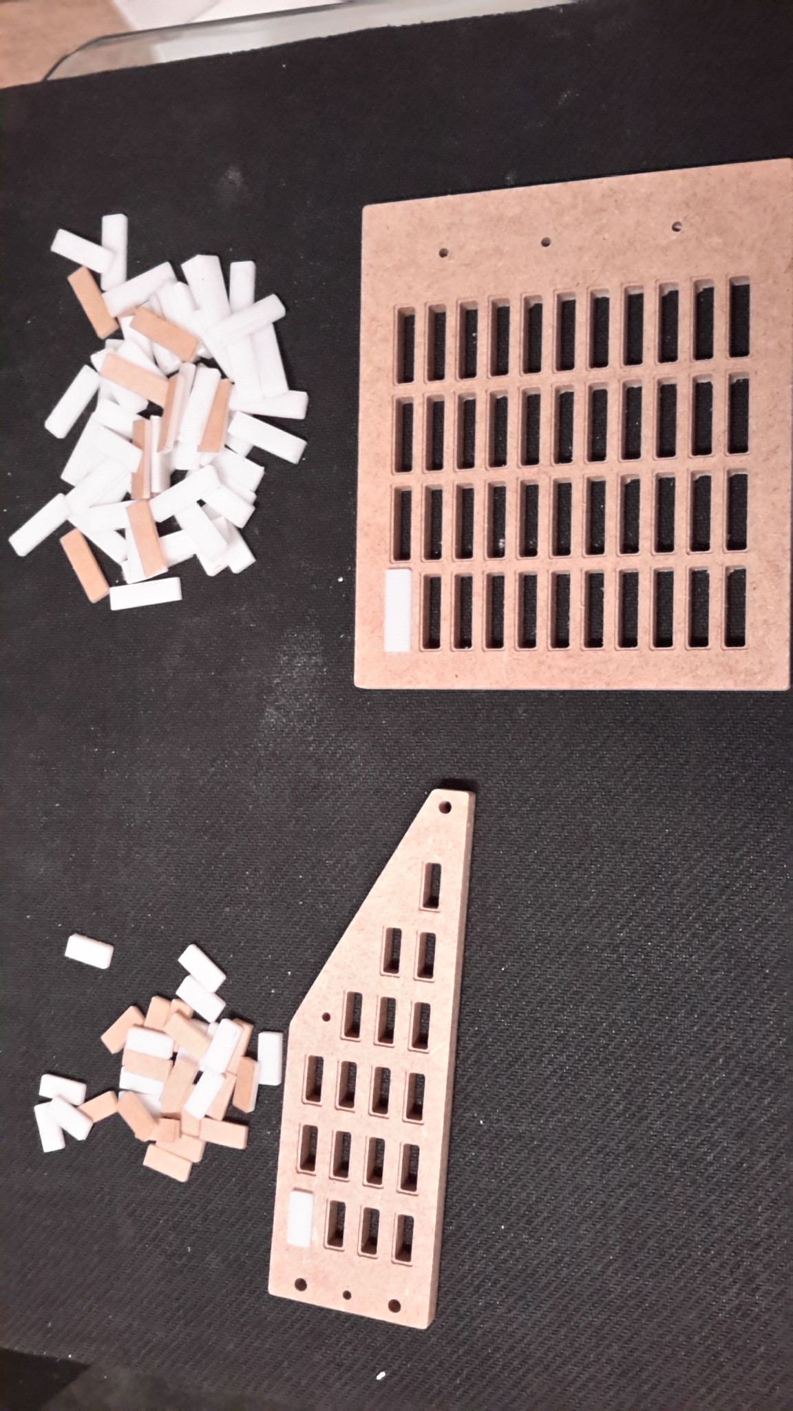
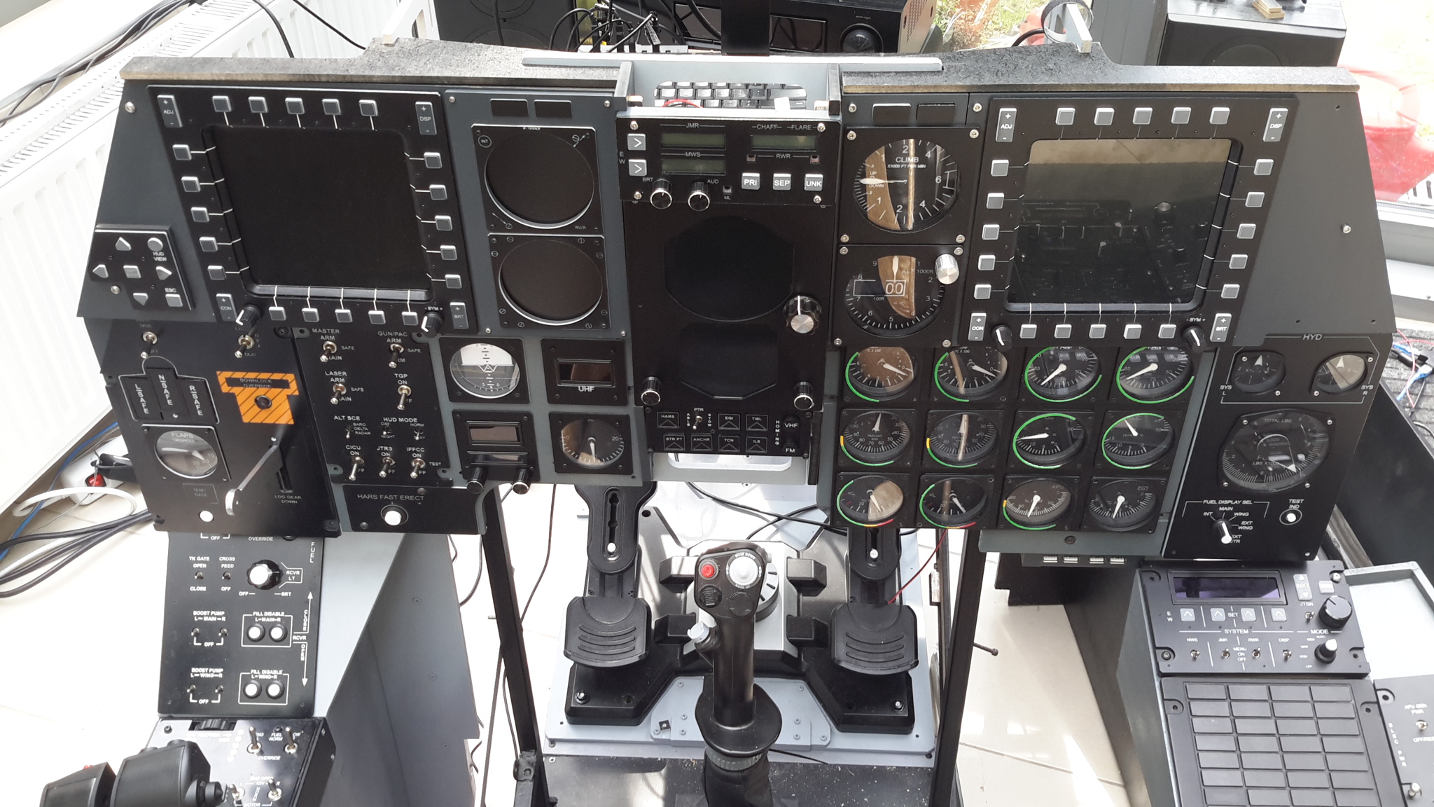
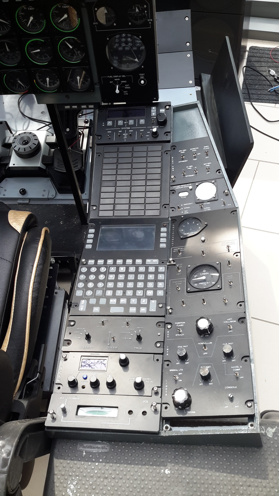
Guys, I thought I would just take a step back and give an update on my progress. I've been doing a lot of bits and bobs on this project, as you can see by my continual stream of questions. I still have a to-do list a mile long, I've started keeping a log of all the jobs I have to do and seem to be adding items faster than I'm knocking them off. I also have to design and build the left console, so a huge amount to do still. However of late I seem to be constantly working on bits on a table somewhere, and my long suffering wife pointed out that there was supposed to be an end product somewhere and that I never seemed to be any closer to finishing. It's a fair point and so in order to demonstrate to her (and also I've come to realise to myself as well) I downed tools and have put everything together that has been built so far so that I can see some progress. I'm pretty happy with it. It's not supposed to be a fully accurate replica, I've modified dimensions, layouts and details to support to requirements of my build. One of the not very obvious requirements I have is that as I move around the world with my work, and so everything that I make has to be able to be disassembled into modules that can go into boxes. That imposes its own unique restrictions. Nonetheless I'm proud of it so far, and I'm pleased at how far I've come and good some details have turned out. I still have to address the elephant in the room sometime, namely the RS485 network. I have bought a TinySine RS485 shield in order to come back to it one day, however I'm still not quite ready yet. No doubt I'll have to ask help on this forum again (with apologies in advance to Hansolo and VincVega), and I am still hopeful that I can enlist the help of someone locally who can work with me and hold my arms at my side when I am about to throw stuff at the wall again (that happened a number of times). Some of my designs and concepts have changed drastically since the outset and I have learned a lot. I have had to learn to use Arduinos, sketches and programming, I2C units, PCF8574 modules, MAX7219 modules, LCD displays, OLED displays, laser engraver, CNC router / engraver, QCAD, Inkscape, custom PCB design, stepper motors and drivers...... the list goes on So I thought I'd share the progress with you all and repeat my thanks for all the help I've been given over the past year Hope you like it Cheers Les
-
Multiple LCD modules on one Nano - faint display
lesthegrngo replied to lesthegrngo's topic in Home Cockpits
Guys, I fixed this by connecting a 5v supply to the VC and GND pins. Lovely clear displays now, and checking the Nano '5v' output showed it only outputs 4.5v, and so is incapable of powering all three. Good lesson learned by me, hopefully this helps you guys too Cheers Les -
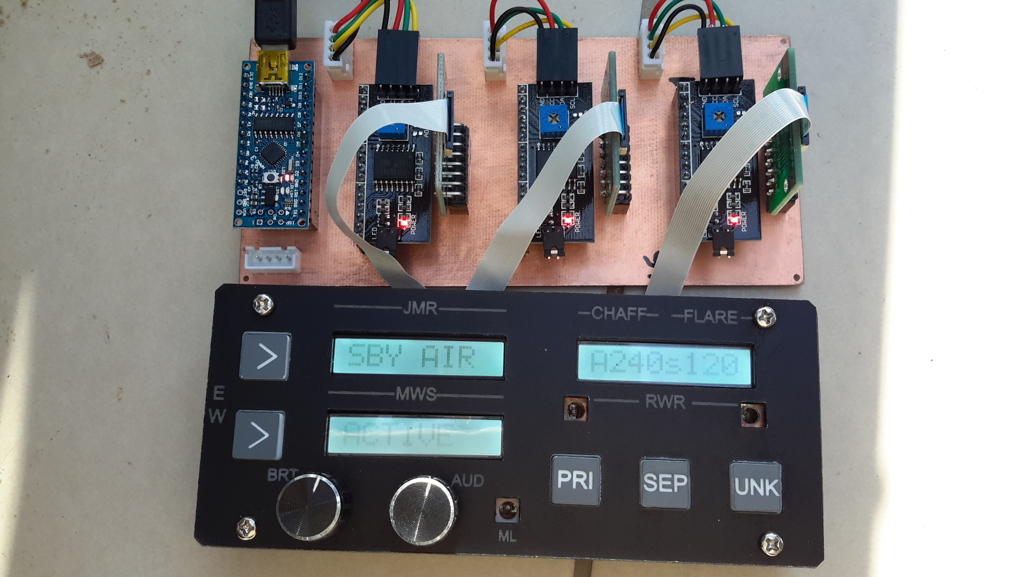
Guys, as you can see my CMSC panel has three 8 x 1 LCD modules in it, and I have been able to make them run off one Nano board. Basically each LCD module is connected to a PCF8574 adapter which allows different I2C addresses However when I was putting it back together after some testing work, I noticed something I hadn't seen before. I connected the LCD modules one by one to make sure they all were connected to the right panel, and as I connected each one, the displays became fainter. Obviously I checked the settings with the potentiomenters, but even at max settings, by the time all three were connected the display was very faint indeed. All the schematics I have seen show the GND and VCC of the LCD displays connected to the Nano GND and 5v pins. Should there be a separate 5v supply to the PCF8574 boards? Cheers Les
-
TISL / Radio selector wheel display output
lesthegrngo replied to lesthegrngo's topic in Home Cockpits
I niggled away at this and have made some good progress, however I have also highlighted some issues that I will have to be aware of going forward when using OLED displays. As I get most of my help from this forum, it seems only fair to put it here on this forum so that others can use it, and hopefully avoid some issues. First off I have the code working for 128x32 and 128x64 modules (as you can see from the attached pictures - the 128x64 module is the one in my altimeter just for testing) Here is the code for the 128x32 module that displays all four TISL digits #define DCSBIOS_DEFAULT_SERIAL #include "DcsBios.h" #include <SPI.h> #include <Wire.h> #include <Adafruit_GFX.h> #include <Adafruit_SSD1306.h> #include "charactersbak.h" #define SCREEN_WIDTH 128 // OLED display width, in pixels #define SCREEN_HEIGHT 32// OLED display height, in pixels #define OLED_RESET -1 // Reset pin # (or -1 if sharing Arduino reset pin) //Comment for barometric pressure #define TISL int updateInterval = 100; //the number of milliseconds between updates struct scrollDigit { int digit; //The digit that is displayed int y; // The vertical position of the digit }; struct disp { Adafruit_SSD1306 display; int width; int numberOfDigits; scrollDigit digits[4]; }; #ifdef TISL disp oled = {Adafruit_SSD1306(SCREEN_WIDTH, SCREEN_HEIGHT, &Wire, OLED_RESET), 30, 4, {{0,0},{0,0},{0,0},{0,0}}}; #endif void setup() { if(!oled.display.begin(SSD1306_SWITCHCAPVCC, 0x3C)) { // Address 0x3C for 128x32 for(;;); // Don't proceed, loop forever } DcsBios::setup(); } void UpdateDisplay() { oled.display.clearDisplay(); for (int i = 0; i < oled.numberOfDigits; i++) { printScrollingDigit(oled.digits[i].digit, oled.width, oled.digits[i].y, i + 1, &oled); } if (oled.width == 16) { oled.display.fillRect(0, 25, 67, 7, BLACK); } oled.display.display(); } int YPos() { return (oled.width + 9) * -1; } void printScrollingDigit(int digit, int width, int y, int pos, disp *oled) { int x = (width * pos) - width + pos; #ifdef TISL switch (digit) { case -1: oled->display.drawBitmap(x, y, c24_Empty, 24, 32, 1); oled->display.drawBitmap(x, y+33, c24_1, 24, 32, 1); break; case 1: oled->display.drawBitmap(x, y, c24_1, 24, 32, 1); oled->display.drawBitmap(x, y+33, c24_2, 24, 32, 1); break; case 2: oled->display.drawBitmap(x, y, c24_2, 24, 32, 1); oled->display.drawBitmap(x, y+33, c24_3, 24, 32, 1); break; case 3: oled->display.drawBitmap(x, y, c24_3, 24, 32, 1); oled->display.drawBitmap(x, y+33, c24_4, 24, 32, 1); break; case 4: oled->display.drawBitmap(x, y, c24_4, 24, 32, 1); oled->display.drawBitmap(x, y+33, c24_5, 24, 32, 1); break; case 5: oled->display.drawBitmap(x, y, c24_5, 24, 32, 1); oled->display.drawBitmap(x, y+33, c24_6, 24, 32, 1); break; case 6: oled->display.drawBitmap(x, y, c24_6, 24, 32, 1); oled->display.drawBitmap(x, y+33, c24_7, 24, 32, 1); break; case 7: oled->display.drawBitmap(x, y, c24_7, 24, 32, 1); oled->display.drawBitmap(x, y+33, c24_8, 24, 32, 1); break; case 8: oled->display.drawBitmap(x, y, c24_8, 24, 32, 1); oled->display.drawBitmap(x, y+33, c24_9, 24, 32, 1); break; case 9: oled->display.drawBitmap(x, y, c24_9, 24, 32, 1); oled->display.drawBitmap(x, y+33, c24_0, 24, 32, 1); break; default: oled->display.drawBitmap(x, y, c24_0, 24, 32, 1); oled->display.drawBitmap(x, y+33, c24_1, 24, 32, 1); break; } #endif } #ifdef TISL void onTislCode1Change(unsigned int newValue) { unsigned int mappedValue = newValue / 2; unsigned int y = map(newValue, mappedValue * 2, mappedValue * 2 + 3, 0, YPos()); oled.digits[0].digit = newValue / 2; oled.digits[0].y = y; } DcsBios::IntegerBuffer tislCode1Buffer(0x1116, 0x1f00, 8, onTislCode1Change); void onTislCode2Change(unsigned int newValue) { unsigned int mappedValue = newValue / 2; unsigned int y = map(newValue, mappedValue * 2, mappedValue * 2 + 3, 0, YPos()); oled.digits[1].digit = newValue / 2; oled.digits[1].y = y; } DcsBios::IntegerBuffer tislCode2Buffer(0x111a, 0x1f00, 8, onTislCode2Change); void onTislCode3Change(unsigned int newValue) { unsigned int mappedValue = newValue / 2; unsigned int y = map(newValue, mappedValue * 2, mappedValue * 2 + 3, 0, YPos()); oled.digits[2].digit = newValue / 2; oled.digits[2].y = y; } DcsBios::IntegerBuffer tislCode3Buffer(0x111e, 0x1f00, 8, onTislCode3Change); void onTislCode4Change(unsigned int newValue) { unsigned int mappedValue = newValue / 2; unsigned int y = map(newValue, mappedValue * 2, mappedValue * 2 + 3, 0, YPos()); oled.digits[3].digit = newValue / 2; oled.digits[3].y = y; } DcsBios::IntegerBuffer tislCode4Buffer(0x1122, 0x1f00, 8, onTislCode4Change); #endif unsigned long time = 0; void loop() { DcsBios::loop(); time = millis(); if (time % updateInterval == 0) { UpdateDisplay(); } } I have to give credit to Middlefart for the base code that I used, essentially I have reverse engineered it for my purposes here. So the issue was that the the numbers being generated were totally different to what I was expecting. In the case of the altimeter, I think the output was a number between 0 and 65535. However in the case of the TISL, depending on which way you choose you get 20 numbers. I used 7 segment displays and LCD displays to get the outputs in a way that I could see. In the case of the integerBuffer, you get outputs of 0, 1, 2, etc all the way up to 19. In the case of stringBuffer it outputs 0, 0.5, 1, 1.5 etc up to 9.5. As result, the original code was essentially converting everything to zeros and 1's, so by correcting the pull down value it allowed me to get the right numbers in the basic displays. From there it was a case of playing with the settings to get the numbers to 'scroll'. After resolving the the output issue the first problem I had was very confusing display behaviour. My intention is to eventually use some 64x32 dot matrix 0.49" OLED modules, one for each digit between the selector wheels, so I was working to get one digit working on one 0.49" OLED. However when I loaded up the sketch, all I got was a truncated digit with just the bottom half showing with some random speckles on the other side of the screen. The resolution is set in the sketch, but for some reason it was not displaying correctly. So I tried the unchanged sketch on one of the 128 x 32 OLED modules I have and suddenly it was displaying to digit correctly, albeit with the speckles remaining on the right hand side. I adjusted the resolution in the sketch to 128 x 32, and bingo, perfectly displayed. I played with the sketch to add the other three digits, and it worked beautifully. Just out of curiosity I adjusted the resolution to 128 x 64 and connected it to the OLED module in my altimeter, and again, perfect. So I reconnected went back to the sketch, adjusted the resolution back to 128 x 32 and reconnected the 128 x 32 module, and suddenly it was corrupted! What I was getting was the characters superimposing (see picture) and some speckles. I realised that the 128 x 32 module I had connected was not the one I had earlier, so I reconnected the other one and it worked perfectly. I have therefore concluded that there are different types of OLED modules, and that by looking at them you cannot tell which is which. Depending on which one you connect it shows different things. The non-working ones appear to be modules that don't support SSD1306, even though they are I2C compatible. So I have concluded that the 0.49" module I have is also not one that supports SSD3106, looking at the order I placed, so I think that I will have to try some different modules. But with all this I also discovered a potential problem that may complicate my design. Assuming that I can get the 0.49" OLED to display properly, if I want to use multiple I2C devices on one Nano, as I did with the CMSM panel and the three LCD modules, I need to be able to assign individual I2C addresses to them. However the 0.49" modules have a static address (0x3c) and do not have the option to change it. The possible option is to use an I2C multiplexer, otherwise I have to resign myself to the use of multiple Nano's. One other point I found was why I could get some Nano's to load the sketch and not others. I have some 'old' Nanos, which are obviously what Arduino IDE calls 'ATmega328P (Old Bootloader), and these can load this sketch, however some newer ones are ATmega168's that will not accept this code. Presumably an onboard memory issue, but now I know about it I can at least deal with it. So success generally with some caveats, hopefully I can find a way around the issues and if I do will post it back here Cheers Les -
Gents, I have been trying to make a sketch for the TISL and radio unit selector wheel displays. The selector wheel itself is a rotary encoder, no problem, but the individual single digit displays are causing me some issues. The intention is to use those little OLED modules as they are small enough to fit and allow space for the rotary encoders underneath on the basis that it will be pretty crowded. However no matter how I try it, I cannot get the digits to display properly on the OLED modules. I have successfully modified Middlfarts lovely scrolling altimeter sketch to use with the fuel quantity display, but when I splice in the code for the selector wheel displays, all I can get is it displays a 1 and a zero, which scrolls as you select up and down. This is the sketch as it stands #define DCSBIOS_DEFAULT_SERIAL #include "DcsBios.h" #include <SPI.h> #include <Wire.h> #include <Adafruit_GFX.h> #include <Adafruit_SSD1306.h> #include "charactersbak.h" #define SCREEN_WIDTH 64 // OLED display width, in pixels #define SCREEN_HEIGHT 32 // OLED display height, in pixels #define OLED_RESET -1 // Reset pin # (or -1 if sharing Arduino reset pin) //Comment for barometric pressure #define ALTIMETER int updateInterval = 100; //the number of milliseconds between updates struct scrollDigit { int digit; //The digit that is displayed int y; // The vertical position of the digit }; struct disp { Adafruit_SSD1306 display; int width; int numberOfDigits; scrollDigit digits[5]; }; #ifdef ALTIMETER disp oled = {Adafruit_SSD1306(SCREEN_WIDTH, SCREEN_HEIGHT, &Wire, OLED_RESET), 24, 1, {{0,0},{0,0},{0,0},{0,0},{0,0}}}; #else disp oled = {Adafruit_SSD1306(SCREEN_WIDTH, SCREEN_HEIGHT, &Wire, OLED_RESET), 16, 4, {{0,0},{0,0},{0,0},{0,0},{0,0}}}; #endif void setup() { if(!oled.display.begin(SSD1306_SWITCHCAPVCC, 0x3C)) { // Address 0x3C for 128x32 for(;;); // Don't proceed, loop forever } DcsBios::setup(); } void UpdateDisplay() { oled.display.clearDisplay(); for (int i = 0; i < oled.numberOfDigits; i++) { printScrollingDigit(oled.digits[i].digit, oled.width, oled.digits[i].y, i + 1, &oled); } //Clear the area below the the numbers if we are using the small font if (oled.width == 16) { oled.display.fillRect(0, 25, 67, 7, BLACK); } oled.display.display(); } int YPos() { return (oled.width + 9) * -1; } void printScrollingDigit(int digit, int width, int y, int pos, disp *oled) { int x = (width * pos) - width + pos; #ifdef ALTIMETER switch (digit) { case -1: oled->display.drawBitmap(x, y, c24_Empty, 24, 32, 1); oled->display.drawBitmap(x, y+33, c24_1, 24, 32, 1); break; case 1: oled->display.drawBitmap(x, y, c24_1, 24, 32, 1); oled->display.drawBitmap(x, y+33, c24_2, 24, 32, 1); break; case 2: oled->display.drawBitmap(x, y, c24_2, 24, 32, 1); oled->display.drawBitmap(x, y+33, c24_3, 24, 32, 1); break; case 3: oled->display.drawBitmap(x, y, c24_3, 24, 32, 1); oled->display.drawBitmap(x, y+33, c24_4, 24, 32, 1); break; case 4: oled->display.drawBitmap(x, y, c24_4, 24, 32, 1); oled->display.drawBitmap(x, y+33, c24_5, 24, 32, 1); break; case 5: oled->display.drawBitmap(x, y, c24_5, 24, 32, 1); oled->display.drawBitmap(x, y+33, c24_6, 24, 32, 1); break; case 6: oled->display.drawBitmap(x, y, c24_6, 24, 32, 1); oled->display.drawBitmap(x, y+33, c24_7, 24, 32, 1); break; case 7: oled->display.drawBitmap(x, y, c24_7, 24, 32, 1); oled->display.drawBitmap(x, y+33, c24_8, 24, 32, 1); break; case 8: oled->display.drawBitmap(x, y, c24_8, 24, 32, 1); oled->display.drawBitmap(x, y+33, c24_9, 24, 32, 1); break; case 9: oled->display.drawBitmap(x, y, c24_9, 24, 32, 1); oled->display.drawBitmap(x, y+33, c24_0, 24, 32, 1); break; default: oled->display.drawBitmap(x, y, c24_0, 24, 32, 1); oled->display.drawBitmap(x, y+33, c24_1, 24, 32, 1); break; } #endif } #ifdef ALTIMETER void onTislCode1Change(unsigned int newValue) { unsigned int mappedValue = newValue / 6553; unsigned int y = map(newValue, mappedValue * 6553, mappedValue * 6553 + 6553, 0, YPos()); oled.digits[0].digit = newValue; oled.digits[0].y = y; } DcsBios::IntegerBuffer tislCode1Buffer(0x1116, 0xffff, 0, onTislCode1Change); #endif unsigned long time = 0; void loop() { DcsBios::loop(); time = millis(); if (time % updateInterval == 0) { UpdateDisplay(); } } I have also used another sketch that works with the altimeter data (someone else's, sorry but I can't remember whose), but again, it only displays a 1 or zero with the radio / TISL data I am clearly misunderstanding what the output is supposed to be, can anyone advise on what I should be doing to show these? Cheers Les
-
The problem for me is that there are a couple of issues. Firstly, each board I make is essentially a prototype, and I often have to make an adjustment or even realise I have got it completely wrong and start again. Depressingly often, to tell the truth! Secondly, due to my engineering based way of making my parts, I find that the software for PCB design doesn't click with me. I have tried a number of them, including Fritzing, and just can't get on with them. If I had someone who knew what they were doing sit down with me and work with me to show me how to design the boards with my 'designs' then I am sure it would be better, but I don't think there is anyone here in Hungary near me to show me. Cheers Les
-
My method is to use Qcad community edition (free) to design the board, and engrave and drill and cut the PCB using my cheap Chinese CNC engraver and GBRL (I use Universal Gcode Sender). I've made loads of PCB's this way, including double sided ones, by drilling little reference holes and via holes. Cheers Les
-
A10C standby attitude indicator - how to reproduce it
lesthegrngo replied to lesthegrngo's topic in Home Cockpits
Ok, printed static version it is then! Cheers Les -
Using IR optocoupler to set zero position for altimeter
lesthegrngo replied to lesthegrngo's topic in Home Cockpits
The unfortunate situation with Coronavirus has had the collateral effect of giving me chance to work on some bits and pieces for my sim pit. I knocked together the sketch below, which with my optocoupler is working to zero the gauge. However once it has zeroed, the gauge never moves again! Is there anything obvious wrong with it? #define DCSBIOS_IRQ_SERIAL #include <AccelStepper.h> #include "DcsBios.h" struct StepperConfig { unsigned int maxSteps; unsigned int acceleration; unsigned int maxSpeed; }; class Vid29Stepper : public DcsBios::Int16Buffer { private: AccelStepper& stepper; StepperConfig& stepperConfig; inline bool zeroDetected() { return digitalRead(irDetectorPin) == 1; } unsigned int (*map_function)(unsigned int); unsigned char initState; long currentStepperPosition; long lastAccelStepperPosition; unsigned char irDetectorPin; long zeroOffset; bool movingForward; bool lastZeroDetectState; long normalizeStepperPosition(long pos) { if (pos < 0) return pos + stepperConfig.maxSteps; if (pos >= stepperConfig.maxSteps) return pos - stepperConfig.maxSteps; return pos; } void updateCurrentStepperPosition() { // adjust currentStepperPosition to include the distance our stepper motor // was moved since we last updated it long movementSinceLastUpdate = stepper.currentPosition() - lastAccelStepperPosition; currentStepperPosition = normalizeStepperPosition(currentStepperPosition + movementSinceLastUpdate); lastAccelStepperPosition = stepper.currentPosition(); } public: Vid29Stepper(unsigned int address, AccelStepper& stepper, StepperConfig& stepperConfig, unsigned char irDetectorPin, long zeroOffset, unsigned int (*map_function)(unsigned int)): Int16Buffer(address), stepper(stepper), stepperConfig(stepperConfig), irDetectorPin(irDetectorPin), zeroOffset(zeroOffset), map_function(map_function), initState(0), currentStepperPosition(0), lastAccelStepperPosition(0) { } virtual void loop() { if (initState == 0) { // not initialized yet pinMode(irDetectorPin, INPUT); stepper.setMaxSpeed(stepperConfig.maxSpeed); stepper.setSpeed(1000); initState = 1; } if (initState == 1) { // move off zero if already there so we always get movement on reset // (to verify that the stepper is working) if (zeroDetected()) { stepper.runSpeed(); } else { initState = 2; } } if (initState == 2) { // zeroing if (!zeroDetected()) { stepper.runSpeed(); } else { stepper.setAcceleration(stepperConfig.acceleration); stepper.runToNewPosition(stepper.currentPosition() + zeroOffset); // tell the AccelStepper library that we are at position zero stepper.setCurrentPosition(0); lastAccelStepperPosition = 0; // set stepper acceleration in steps per second per second // (default is zero) stepper.setAcceleration(stepperConfig.acceleration); lastZeroDetectState = true; initState = 3; } } if (initState == 3) { // running normally // recalibrate when passing through zero position bool currentZeroDetectState = zeroDetected(); if (!lastZeroDetectState && currentZeroDetectState && movingForward) { // we have moved from left to right into the 'zero detect window' // and are now at position 0 lastAccelStepperPosition = stepper.currentPosition(); currentStepperPosition = normalizeStepperPosition(zeroOffset); } else if (lastZeroDetectState && !currentZeroDetectState && !movingForward) { // we have moved from right to left out of the 'zero detect window' // and are now at position (maxSteps-1) lastAccelStepperPosition = stepper.currentPosition(); currentStepperPosition = normalizeStepperPosition(stepperConfig.maxSteps + zeroOffset); } lastZeroDetectState = currentZeroDetectState; if (hasUpdatedData()) { // convert data from DCS to a target position expressed as a number of steps long targetPosition = (long)map_function(getData()); updateCurrentStepperPosition(); long delta = targetPosition - currentStepperPosition; // if we would move more than 180 degree counterclockwise, move clockwise instead if (delta < -((long)(stepperConfig.maxSteps/2))) delta += stepperConfig.maxSteps; // if we would move more than 180 degree clockwise, move counterclockwise instead if (delta > (stepperConfig.maxSteps/2)) delta -= (long)stepperConfig.maxSteps; movingForward = (delta >= 0); // tell AccelStepper to move relative to the current position stepper.move(delta); } stepper.run(); } } }; /* modify below this line */ /* define stepper parameters multiple Vid60Stepper instances can share the same StepperConfig object */ struct StepperConfig stepperConfig = { 400, // maxSteps 2200, // maxSpeed 1000 // acceleration }; // define AccelStepper instance AccelStepper stepper(AccelStepper::DRIVER, 11, 10); // define Vid29Stepper class that uses the AccelStepper instance defined in the line above // v-- arbitrary name Vid29Stepper alt100ftPointer(0x107e, // address of stepper data stepper, // name of AccelStepper instance stepperConfig, // StepperConfig struct instance 9, // IR Detector Pin (must be HIGH in zero position) 0, // zero offset [](unsigned int newValue) -> unsigned int { /* this function needs to map newValue to the correct number of steps */ return map(newValue, 0, 65535, 0, stepperConfig.maxSteps-1); }); void setup() { DcsBios::setup(); } void loop() { DcsBios::loop(); } Cheers Les -
DCS BIOS - Calibration of non-linear gauges
lesthegrngo replied to lesthegrngo's topic in Home Cockpits
Thanks! I'll take a look and see how I can work that into the sketch Cheers Les -
Gents, the A10-C engine Fan gauges are not a linear scale. with zero to 50% fan speed taking up less than 75 degrees of travel, the next 25% rpm taking up about 25 degrees, and the remaining 25% needing about 190 degrees rotation. Other than reprinting the fan gauge faces as a linear scale, is there any way to modify the DCS BIOS sketch to match the correct movement to the scale? Cheers Les
-
Hi again guys While trying to finish off the dash I realised that I had completely overlooked the standby attitude indicator. The other three instruments in that cluster are fine, but short of adding either another screen (that would make 6 total) for use with Helios / Ikarus or a static representation of the gauge with a colour print, I can't think of any way. I have a small 3.5 TFT screen that works with an Arduino Uno(orphaned when I went to a 5 inch screen for the CDU) but suspect that the programming needed to make the standby attitude indicator would be a stretch form most people, let alone my limited abilities. What, if any, other options exist? Cheers Les
-
Using IR optocoupler to set zero position for altimeter
lesthegrngo replied to lesthegrngo's topic in Home Cockpits
Thanks, looks like some great info there Cheers Les -
Hi guys, I'm still moving this all forward slowly, now that I have a substantial amount of the cockpit if not finished, then working in need of tidy up. one of the items on the list was the altimeter, which is one of the very few (physical) gauges I am making that requires unlimited rotation. Middlefart has kindly provided us all with his rather nice scrolling OLED display sketch, so now all that remains on that particular gauge is to be able to set the zero position using either an IR optocoupler or a hall effect sensor. My preference for the IR optocoupler route is simply because I have one supplied as part of an arduino starter set. I found this sketch on this forum thread https://forums.eagle.ru/showthread.php?t=145193 // include AccelStepper library #include <AccelStepper.h> // include DcsBios library #include <DcsBios.h> #include <Servo.h> // DcsBios-related declarations DcsBios:ProtocolParser parser; #define STEPS_PER_REVOLUTION 240 #define ZERO_OFFSET 0 AccelStepper stepper; // Defaults to AccelStepper::FULL4WIRE (4 pins) on 2, 3, 4, 5 int currentStepperPosition = 0; // current stepper position (in steps, from 0 to STEPS_PER_REVOLUTION-1) signed long lastAccelStepperPosition; void setup() { Serial.begin(250000); pinMode (12,INPUT); // LOW when in zero position, HIGH otherwise // set up stepper motor for zeroing stepper.setMaxSpeed(1000); stepper.setSpeed(500); // run clockwise until we detect the zero position while (digitalRead (12)==1) { stepper.runSpeed(); } // add zero offset stepper.runToNewPosition(stepper.currentPosition() + ZERO_OFFSET); // tell the AccelStepper library that we are at position zero stepper.setCurrentPosition(0); lastAccelStepperPosition = 0; // set stepper acceleration in steps per second per second // (default is zero) stepper.setAcceleration(1000); } void loop() { // handle DcsBios communication while (Serial.available()) { parser.processChar(Serial.read()); } DcsBios:PollingInput::pollInputs(); // move stepper motor stepper.run(); } void onDcsBiosWrite(unsigned int address, unsigned int value) { if (address == 0x107e) { digitalWrite (13,1); unsigned int alt100ftValue = (value & 0xffff) >> 0; // convert data from DCS to a target position expressed as a number of steps int targetPosition = map(alt100ftValue, 0, 65535, 0, STEPS_PER_REVOLUTION-1); // adjust currentStepperPosition to include the distance our stepper motor // was moved since we last updated it int movementSinceLastUpdate = stepper.currentPosition() - lastAccelStepperPosition; currentStepperPosition += movementSinceLastUpdate; lastAccelStepperPosition = stepper.currentPosition(); if (currentStepperPosition < 0) currentStepperPosition += STEPS_PER_REVOLUTION; if (currentStepperPosition > STEPS_PER_REVOLUTION) currentStepperPosition -= STEPS_PER_REVOLUTION; int delta = targetPosition - currentStepperPosition; // if we would move more than 180 degree counterclockwise, move clockwise instead if (delta < -(STEPS_PER_REVOLUTION/2)) delta += STEPS_PER_REVOLUTION; // if we would move more than 180 degree clockwise, move counterclockwise instead if (delta > (STEPS_PER_REVOLUTION/2)) delta -= STEPS_PER_REVOLUTION; // tell AccelStepper to move relative to the current position stepper.move(delta); I'm using an X27 type stepper motor, which has already been modified to remove the limiting pin inside. The sketch has to be changed for use with a stepper driver (an A4988 module) as this sketch seems to drive the stepper directly. The optocoupler module is one of these https://www.ebay.com/itm/TCRT5000-IR-Infrared-Line-Track-Follower-Sensor-Obstacle-Avoidance-Module/202058803237?hash=item2f0ba4a825:g:z-8AAOSwSZFZwAJD So I am going to put a test together, then see if I can successfully get the sketch working correctly with the hardware. If anyone has experience of this and can advise as ever I would be grateful for the input Wish me luck! Cheers Les