lesthegrngo
-
Posts
1245 -
Joined
-
Last visited
Content Type
Profiles
Forums
Events
Everything posted by lesthegrngo
-
Modular A-10C gauge controller for DCS Bios
lesthegrngo replied to lesthegrngo's topic in Home Cockpits
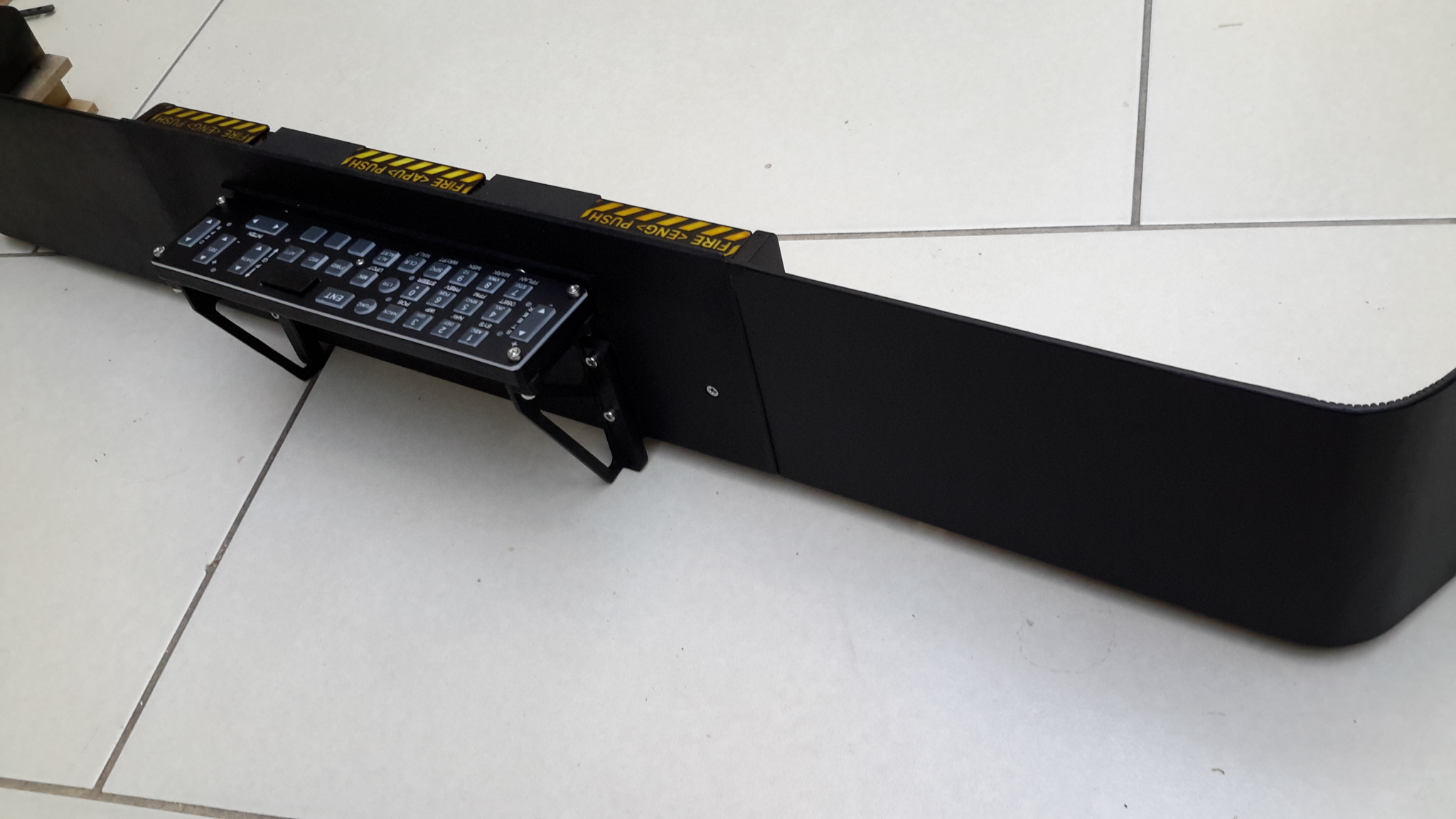
Here is the coaming almost complete - sorry about the pictures being upside down The fire handles say PUSH rather than pull deliberately, just in case someone wants to point that out, I couldn't be bothered to make them pull type at the moment. The UFC needs a reinforcing plate behind it as it is a bit thin and flexes a bit but that's easy enough. I thought the cut and shut method would work for the curves and so it proved, although as ever a nice thick coat of matt black covers a multitude of sins :music_whistling: Best of all, once screwed to the top of the dash it has consolidated the assembly really well, making the whole lot feel more solid. Cheers Les
-
I had something similar, try a different encoder setting. Failing that, try flashing the Bodnar board with the latest firmware, I had one that needed that in order to get it working Cheers Les
-
Modular A-10C gauge controller for DCS Bios
lesthegrngo replied to lesthegrngo's topic in Home Cockpits
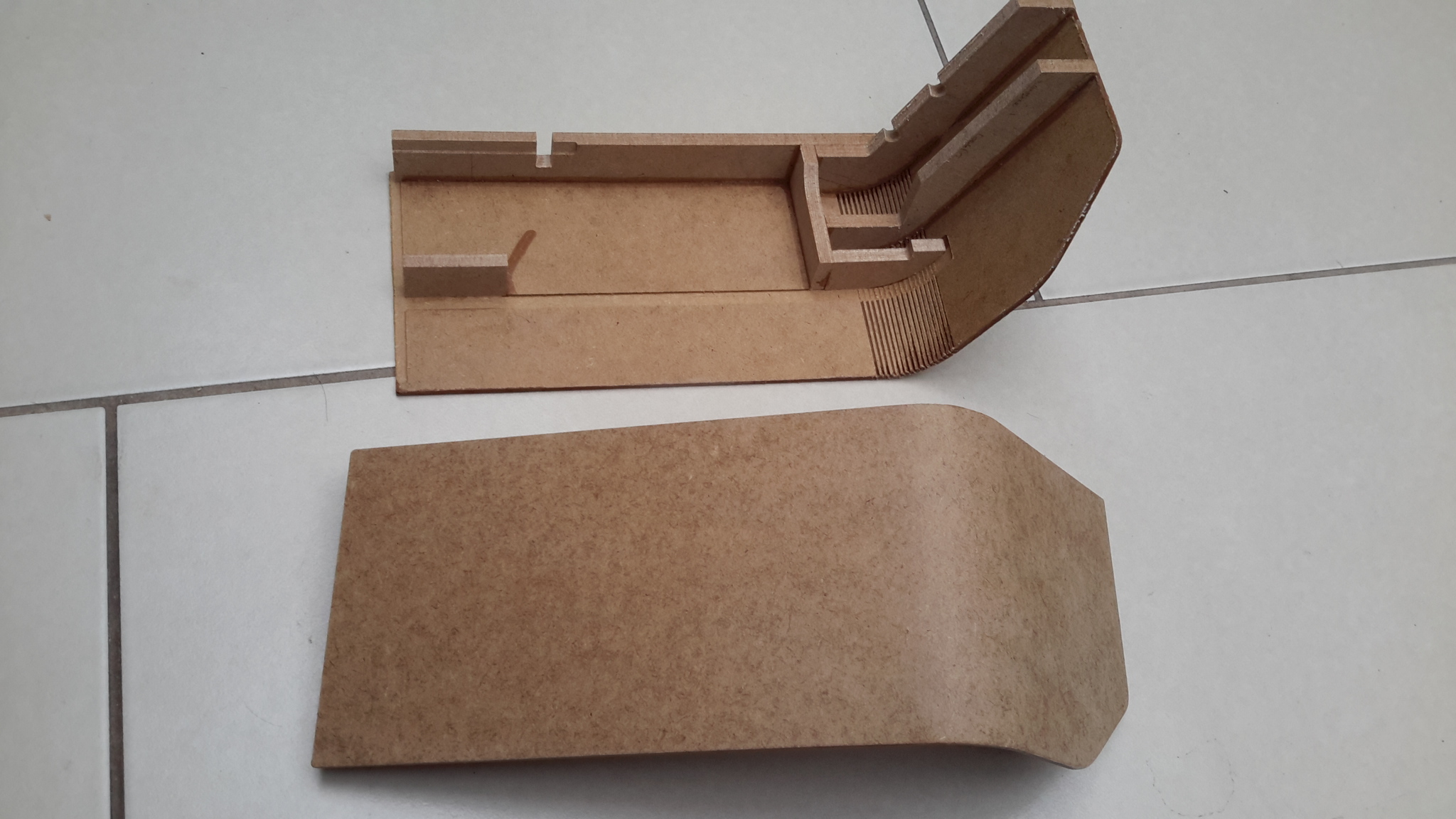
Here are the dash 'brow' coamings, basically MDF machined so that I can bend the MDF to the correct curve. Thankfully a simple curve not a compound one, and once sanded and painted I think that they will look OK Cheers Les
-
There's no official build thread, this is the nearest to it that I have got https://forums.eagle.ru/showthread.php?t=242208 I never planned to do a full cockpit, but as time goes on I have been adding more and more to it, certainly much more than I originally envisaged. It's not accurate, the intent was to make what scale aircraft modelers call 'stand-off' versions, which essentially look sort of correct but are adjusted to make sure they function within the limitations imposed by scale / tools / materials / what-have-you. That means I can play with sizes, switch types etc. The basis for the rig is my F1 simulator frame I made back in 2007, so everything I make has to be made to fit that. That creates some pretty interesting conflicts in the design. Additionally, I move around the world a lot with my job (this is the tenth country I have lived in) so everything I do has to be capable of being essentially broken down and 'flat-packed' - sort of Ikea style - hence the reference to 'modular' in the thread. Everything in the build is modular to a greater or lesser degree. I have designed it all my self using a combination of solidworks 2008 and Qcad, and the materials are a combo of Ebay sourced bits and bobs (mainly electronic components, OLEDS, LCD modules, Screens, Arduinos) and stuff I can get locally. The latter imposes its own restrictions too, as MDF sheets are not for sale here in Hungary, only plywood. However MDF is much better for a lot of the panels, so I end up using textured floor coverings, which are pieces of MDF covered in a plastic or similar covering to give it colour and texture. Of course, that means you have to be creative due to the texture (where possible I try to remove it) but more importantly the thickness of the material varies wildly, so my build is littered with bits made from odd thicknesses! But despite this, I have surprised myself with what I have been able to achieve and am really happy with both the project and my progress - well except for RS485, anyway.... There are parts that I look at and think 'I could do that better' and maybe one day I will, but you have to balance looks and functionality with time, after all the intent is to finish it and use it. For example my fire 'handles' are actually push switches, and are marked with the word 'PUSH' instead of 'PULL' as in the real thing. Why? Because it is a lot quicker to do like that right now, and in game it is used so infrequently that for the purposes of my use will do fine Purists will not like it. But I do, and I'm building it for me and not them, so that's OK. But that is not to say I don't admire some of the incredible builds being shown on these pages Cheers Les
-
Well, I have got something that works, looks OK and am happy with. I admire perfectionists, and love the attention to detail but there comes a point where you have to say 'OK, good enough and I'm happy that it works' and move on to the next part rather than get too focused on one detail. But that is how I build. How you build is entirely up to to you and I wish you well with it. Cheers Les
-
Experiments with stepper motor drivers for gauges
lesthegrngo replied to lesthegrngo's topic in Home Cockpits
Yeah, I read the same article which is why I got some of the AX1201728SG chips - couldn't get them to work, which is a shame, as it would have been interesting to see if there was any difference I still have three of them so maybe will have another go, but maybe the chips I got were no good Cheers Les -
Want me to send the .json file that works for my version of the tool? Les
-
I definitely had a 'woods for the trees' moment there... I had based my thoughts on the design with the nano boards on it, when in actual fact they are no longer there, so I have the space they used to occupy. The optical sensor and hardware will easily fit in the space between the PCB and the back of the gauge face and I just need to make an extension shaft for the pointer with the reflector on it. The Stepper motor itself can sit where the Nanos used to be. Thanks for pointing out what should have been obvious! Cheers Les
-
All, you can never have enough problems to bitch about so I have decided that I want to try and get the tiny little single digit gauges on the A10 EGT and core RPM gauges to work correctly. I have worked out that by dressing the casing of the X27 stepper motors I can just fit them side by side with enough room to allow me to accommodate the axis of the secondary gauge. It is tight, but that bit is doable. The problem is that in common with the altimeter gauge, it is a constant rotation item that requires a zero position sensor in order to work properly. The altimeter is easy as it is a large gauge with plenty of space both behind it for a TCRT5000L optocoupler, and due to the diameter in the gauge face for an unobtrusive slit in the face itself for the optocoupler to work through. The tiny sub gauges don't have the space, so I need to find an alternative. My first though was a hall effect sensor and a 2mm diameter magnet on the pointer, but at that size I believe it will be too inaccurate ( the diameter of the gauge is 15mm) even though I can squeeze the hardware in. Optocouplers need too much space, I can't see how I can get one in there unless there is something like a surface mount device like the SFH9240 IR Sensor SMD Reflective Interrupter. I need to look into the physical size of those to see. So beyond that, are there any other options available for this purpose that would fit? Cheers Les
-
Experiments with stepper motor drivers for gauges
lesthegrngo replied to lesthegrngo's topic in Home Cockpits
Yeah, maybe I need to be a bit more thorough looking at the halfstep settings, see if they can be refined. Considering the irregular stepping of the 16th stepping settings, it's pretty amazing that it is as smooth as it is Les -
Thankfully the A10 coaming is pretty simple, with no compound curves, and seeing as I am not trying to make a 100% accurate replica, I think just using a simple radius and the cut and shut method *should* work. I used in an albeit smaller part for my son's HE111 throttle control quadrant for a game he plays (can't think which) and that came out OK once it was sanded. Ultimately I suppose, if it looks and works OK, it is OK! Les
-
Experiments with stepper motor drivers for gauges
lesthegrngo replied to lesthegrngo's topic in Home Cockpits
Back again after an evening pondering yesterdays results. The non linearity of the results bugged me so I starting wondering if I had actually collected enough test points to make a proper sample for each case, and maybe was distorting the results. As a result I went back and redid 9 of the tests, and repeated them so that each one reflected ten separate pointer steps, in other words I kept clicking on the slider adding one unit until I had ten repeatable pointer movements. Each movement is small, and mostly detected by listening for the faint click, rather than having some fancy measuring equipment. I had read somewhere that input cadence can have an effect on whether a step can be missed or not, so to counter this, I made sure that I clicked at as near a constant rate as I could, and I repeated the tests to make sure that they movements occurred in the same points. I would like to tell you it was interesting but it did get a bit tedious! For reference the last five tests using the progressively increasing microstepping value was conducted at 1200 max speed and 12000 max accel. So the first discovery was that depending on the microstepping rate, the behaviour of the stepping changed dramatically. For full stepping and half stepping, the steps were equally spaced, and matched the theoretical mathematical step ratio. So, for 400 steps at fullstep mode, mathematically it should be 163.34 per step, and I was getting 164, and 800 at half stepping is 81.67, and I was getting 82. So they correlate almost perfectly But once you get beyond halfstepping, the picture changes. What I found was that the step spacing was not even, so for instance at quarterstepping, with 1600 steps, mathematically each step is 40.83 units. What you actually get is a step at 41 units, then a gap of about 122 units to the next step, equating to 3 times the step value, then 41 units to the next step, then 122, then 41 and so on. So essentially, it does a step, step, miss, miss, step, step, miss, miss repeating sequence That is also the case for eighthstepping, mathematically it should be 20.42 per step, but again you get the repeating step, step, miss, miss pattern Once you get to the sixteenthstepping, it changes yet again, as it goes to a two step, 14 miss repeating pattern. Mathematically it should be 10.21 per step, but in reality you get two steps about 10 units apart then a gap of about 140 units until the next step. I have no idea whether this is correct behaviour, but in concept it seems that something is not correct. It may go some way to explain why despite microstepping being theoretically smoother, it does not give those benefits in practice. For me, I would like to see why the microstepping is not using even steps and how the spacing of the steps is defined. I am going to try and get some advice on this behaviour, but if anyone has any thoughts as to why this is happening I would like to hear from you. I have one parting thought - I am assuming that it is the stepper driver controlling this, and it is not a characteristic of the stepper motor, as I assume the motor just does what it is told and the microstepping is all set by jumper pins on the A4988 driver. The Arduino and stepper cannot influence the microstepping, can it? Cheers Les -
Very impressive! Can you give a bit more detail - I assume that DCS BIOS is still the source of the data? Is the Ethernet in lieu of RS485? Cheers Les
-
3D printed? If so, must have taken a while, and clearly your printer bed is larger that the one on my Lulzbot Mini. It makes nice prints, but limited to a 6 inch cube. For the dash brow on my A10 dash, I will have to use MDF and make a load of parallel cuts with a 30 degree engraving bits so that I can bend the curve around the edges, sort of lobster back style. I hope that it will be good enough, but will have to use the 'suck it and see' approach. Failing that I will have to use my old balsa modelling technique and steam bend a load of 1/32 balsa sheet and glue it like a ply. Hopefully the cut and bend method works as it will save a lot of hassle! Cheers Les
-
Nice work, but mine is done and I'm happy with it (for that read "I can't be bothered to redo it") For the gauge face on mine, I just used Qcad and Inkscape to make something that looked OK and fitted in my pre-existing dash parts without too much hassle. I disappear down too many rabbit holes as it is! Cheers Les
-
Modular A-10C gauge controller for DCS Bios
lesthegrngo replied to lesthegrngo's topic in Home Cockpits
Thanks John Yes, that's the process I use, rattle can spray paint on what they call opal white acrylic. I use one of the K40 clone laser cutters, which after replacing the cheap laser tube with a better one (I think it was from TenHigh) has been great, for the price Cheers Les -
Am I right in thinking that the HUD would be at best only partly functional? I thought about something similar for my build, but the complications of parallax, and the fact that the HUD sighting would have to be matched perfectly with the on-screen made me realise that it was way beyond my meagre skills to attempt. The best I would have hoped for is maybe projecting some basic speed and altitude data Nice build, just in case someone hasn't said so before :smilewink: Cheers Les
-
Experiments with stepper motor drivers for gauges
lesthegrngo replied to lesthegrngo's topic in Home Cockpits
There was one thing I forgot to mention when I was writing this. I'd seen it but filed it away for a subsequent check, and went back to it this morning as it had been nagging at me. The diagnostic software allows you to choose the input value via a slider between 0 and 65335, emulating what the game output sends to DCS BIOS. When you look at my maxsteps value in my final setup, logically and mathematically, for each 7 steps or so, you should get one microstep of movement. You can increment the slider value by one by clicking on the right hand side of the slider button. In actual fact, it does not behave like this. What I found was that it took 27 steps before you got any pointer movement, repeatably. So with that in mind, I did a few more tests, with the following results @ 400 maxstep, fullstep with 1200 maxspeed 12000 maxaccel it needed 164 units for pointer movement @ 800 maxstep, halfstep with 1200 maxspeed 12000 maxaccel it needed 84 units for pointer movement @ 1600 maxstep, quarterstep with 1200 maxspeed 12000 maxaccel it needed 164 units for pointer movement @ 3200 maxstep, eighthstep with 1200 maxspeed 12000 maxaccel it needed 41 units for pointer movement @ 6400 maxstep, sixteenthstep with 1200 maxspeed 12000 maxaccel it needed 103 units for pointer movement @ 10000 maxstep, sixteenthstep with 1200 maxspeed 12000 maxaccel it needed 7 units for pointer movement So while there is some linearity in some of those results, it's not a direct rate As a result I wondered what the difference would be changing the maxspeed and maxaccel values So, keeping with sixteenthstepping these are the results @ 10000 maxstep, sixteenthstep with 6000 maxspeed 12000 maxaccel it needed 20 units for pointer movement @ 10000 maxstep, sixteenthstep with 12000 maxspeed 12000 maxaccel it needed 33 units for pointer movement @ 10000 maxstep, sixteenthstep with 6000 maxspeed 6000 maxaccel it needed 27 units for pointer movement @ 10000 maxstep, sixteenthstep with 500 maxspeed 12000 maxaccel it needed 20 units for pointer movement @ 12000 maxstep, sixteenthstep with 6000 maxspeed 12000 maxaccel it needed 82 units for pointer movement @ 12000 maxstep, sixteenthstep with 6000 maxspeed 6000 maxaccel it needed 22 units for pointer movement So again, a very non-linear relationship apparently, and affected by all three parameters. I am not a mathematician, and don't intend to start to be now, but my feeling is that there is probably a direct relationship between the three numbers that means that some will divide better than others. It's probably some computer type number like 128, 256, 512, like memory counts or something. I'm not clever enough to know. I also have to say that at least visibly I could not see any obvious relationship between the step value and pointer movement smoothness. However it is entirely possible that when the figures are all set correctly that it reduces mismatches and therefore makes for more accurate movement. So I hope that there is someone out there that can use this or at least shed some light on why it behaves the way it does, it would be good if we had a way of empirically determining the best settings for the gauges Cheers Les -
***** EDIT**** Please note that there is more information below, and due to changes in testing I have had to redo some of the tests to better reflect the actual stepping part in my second post. I will keep the original in there so people can see the progression, but the last post concerns some more empiric data that I hope will allow us to better understand the interrelation between DCS BIOS and stepper motors. Hopefully I don't bitch too much...:smilewink: All, I had successfully made a load of gauges for my rig, and like a little kid I end up sitting in front of it every now and then playing with the throttles and so forth just to see the gauges all do their thing; it's rather compulsive! However I am not completely happy with them, in as much that they don't move as smoothly as I would wish them to, and they are a bit noisy in action too. I have a couple of setups currently, the changes of which are due to the evolution of the build. When I first started I used Craig's great set of info he posted on his site to get me going, and as a result got myself the X27-68 stepper motors, and the EasyDriver stepper driver boards. My set of 12 engine and APU gauges all have that setup. They do work, however as mentioned I find them to be a bit jittery and noisy, but the biggest problem I had during development of the gauges was the sensitivity of the EasyDriver boards. I have them plugged directly into matching headers on the PCB's, which have headers for the (now unnecessary) Nanos and RS485 chips. Despite this relatively stable connection, I have four EasyDriver boards sitting on my desk that are no good. If the connection is not 100% they just blow, and they are irrecoverable. I'd committed myself to the EasyDrivers for the engine gauges at an early stage, so as the large blank PCB's were not cheap (at least not here in Hungary) and the PCB's themselves quite a lot of work, I kept with them. I have them working and as documented on another thread was able to replace the Nanos with patch boards to allow me to connect all 12 gauges to one Mega. One advantage they have is that I don't have to connect the Arduino 5v and GND to them, the step and direction connections to each one is sufficient. But they do have downsides. I've mentioned the jittery movement, the noise and the sensitivity but there is one other aspect that is a concern. They run hot, and I mean hot. I have left them connected for hours at a time to check them and they stay hot but don't cause issues, but I find myself being a bit nervous about it. So during my development of the initial batch of gauges, I had a board I was using for testing blow, and as I still needed to do some testing but would have to wait for the replacement boards to come from China, I experimented with some A4988 boards I had as spares for my CNC router. Straight out of the box I made the following observations Firstly, the A4988 boards have a heatsink and when connected run a lot cooler. They are also smaller, with a pin layout that makes for a very solid connection using headers, although the heatsink makes them fractionally taller than the EasyDrivers. The other installation related issue is that due to the small form factor and close spacing of the pins I inadvertenly mis-connected it, and yet it continued to function, so is much more robust. Once connected with the same sketch and stepper motor as for the EasyDriver, it was clear that the number of steps (maxsteps) needed for the A4988 is far less than for the EasyDriver in the basic setup. In function, once the steps were reduced to a correct value it seemed subjectively a bit smoother and a bit quieter. As a result, my subsequent designs have incorporated A4988 boards, and I will continue with this as I believe it to be better. For info I briefly tried the AX1201728SG type stepper drive boards - actually they are surface mount chips I had to mount to adapter boards. Theoretically they are capable of driving four boards each and anecdotally provide very smooth operation for X27-86 type steppers using only a 5v feed, but I could not get them to work. Whether they were duff chips (bought from ebay) or that I damaged them mounting them to the adapter boards I can't say, but sadly I cannot give any info on how well they work. But I did want to try and see if I could make the gauge movement with the A4988 drivers better, so today I played around with one using a trial gauge. One part of the stepper driver concept is that of microstepping, and I wanted to see if that would make a difference. There are three pins on the A4988 bords marked MS1, MS2 and MS3. Looking on the internet, there is a chart that shows the logic of the microstepping, so I used that to do some tests. It may be obvious to many electronics engineers out there, but I had to look up what 'pull high' and 'pull low' meant on the charts, but thankfully it is as simple as pull high means connect to the input voltage (in this case 5v as output from the Arduino) and pull low means connect to ground. So with a test circuit and some jumper leads I did some tests. I used the LENG oil pressure sketch (I'll attach in below when I can) that was being used on the main engine instrument panel as this was one that I could use with Bobobears testing software. First up was it in unmodified form, and as expected the needle went full scale anticlockwise until it hit the internal stop, chattered there for a second or so then went full scale in the opposite direction to the opposing stop. In use with the diagnostic program, the max steps value made it impossible to use, so I dropped the max steps value down from 4900 to 400. Immediately it was better, and the gauge ran within the 315 degree arc using the diagnostic program, but was still jittering in its movement and there was significant chattering sounds during operation. One characteristic that caught my eye was that sometimes during movement from low to high or vice versa when there was a significant change, the needle looked like it gets caught momentarily, with a distinct jerk in the movement. Second up, I tried the intermediate steps of connecting MS1 to 5v (I was working on the assumption that if you do not connect relevant MS pin to 5v the internal wiring of the A4988 pulls it low). With the pin connected, the gauge travel and speed became lower, and by no means smooth. If anything it seemed to be a more stop start movement. Changing the maxsteps value improved the travel, but the quality of the movement was still poor. Connecting up MS2 decreased the travel and smoothness yet again, and when I connected all three MS pins, the movement was virtually eliminated (locically) until the maxsteps value was upped. With all three microstepping pins connected I could use a maxstep value of 10000, but the movement was painfully slow and gritty. I then started playing with the acceleration and maxspeed values. In reality, these are much more powerful in their effect than the maxsteps value, and the microstepping levels. By increasing the maxspeed value, the movement became noticeably smoother up to a point. Beyond that point it degenerated again, as it seems that the pointer would move very fast, to a point where it would have to stop and wait for the command signal to catch up. The movement was horribly jerky. So it is clear that maxspeed is one where you can do too much. In my limited testing, Maxaccel needs to be increased in line with maxspeed, but whereas you can go too far with max speed, max accel seems to need to be high but seems indifferent to being set too high. Presumably the maxspeed value limits its effect. A point to note is that at the maximum microstepping setup the ill effects of too much maxspeed and maxaccel are attenuated, the problems are much more evident with lower microstepping. In the end, once you have correctly set the three step values, there is not much difference when you use microstepping but it has shown me the following The max steps value must be set as high as you can, but without the stepper going full range. Ideally it would be 99% of the max travel available The intermediate microstepping levels are more susceptible to poor setups, and also seem to be prone to pointer bounce; fullstepping and max microstepping is more tolerant Full microstepping does, when set up, give subjectively smoother movement, however it is not as much as I had hoped The pointer seems to have more jitter at the moments of initial movement and when the pointer gets near the end of the commanded travel. I don't know if there is an in built algorithm in the accelstepper.cpp library that it uses, but it looks like when it starts to accelerate and slow down it loses control of the movement. To conclude this, I have chosen to use the following parameters on my gauges where I can (ie those with A4988 boards) sixteenth microstepping (all pins to 5v) maxsteps set to circa 10000 dependent on individual calibration needs maxaccel set to 6000 maxspeed set to 6000 I wish I could say I found a really good setup that eradicates the noise and jitter, but unfortunately all I could do was reduce it a bit, but hopefully this helps someone Cheers Les
-
my 3018 CNC router has them too Les
-
Modular A-10C gauge controller for DCS Bios
lesthegrngo replied to lesthegrngo's topic in Home Cockpits
Up Front Controller finished, now have to complete the dash brow on which it will fit. I have to say, this was one of the easiest panels I've made so far, and one of the thinnest, at about 10mm thick. Hope you like it Cheers Les
-
They are pretty small, aren't they? But I have switched over to them for any new items I make, as I find them so much more tolerant of issues. The easydrivers seem to have a high fail rate, and if you have a weak connection on any connections, particularly the power or stepper connections, they blow. The A4988's don't do that. I will be playing around with the microstepping today as i am convinced it will make the gauge movement less noisy and smooth, will report back with findings Cheers Les
-
Is the seat a force feedback type? Cheers Les
-
Very nice work, loving watching this evolve! Cheers Les
-
I have a 3.5" TFT that was my original CDU screen, before I made the (mistaken, now I realise) jump to a 5" unit. I always wondered whether it could be used for the clock, but it's the standby attitude indicator that I always thought would be nice for that. As you say, the size is not quite right, but compared to my crappy printed version........ Like you I also wondered about getting another LCD monitor for that entire panel. Trouble is, it would be a major redesign of what I have, and goodness knows how many times I've gone back on a design and lost a lot of time doing so. Also, it would mean a sixth monitor and I'm not sure whether my rig PC would be able to handle it . It already has a 1070 GTX and GTX660 in it, and the noise of the fans when in game is pretty obtrusive already. Anyway, enough dreaming, I have to finish what I've started already. By the way, new record for slow delivery - ordered 20th January, arrived 29th May, but I suppose I should be glad it got here at all in the current situation Cheers Les