lesthegrngo
-
Posts
1245 -
Joined
-
Last visited
Content Type
Profiles
Forums
Events
Everything posted by lesthegrngo
-
How to set up toggle switches (a tutorial)
lesthegrngo replied to Spy Guy's topic in PC Hardware and Related Software
Yes, that was extremely helpful - there are a number of ideal examples in there and using this and cross referencing the other data, I think I can at least start having a proper go. I hope to report some success shortly Again, many thanks for your help and patience Les -
How to set up toggle switches (a tutorial)
lesthegrngo replied to Spy Guy's topic in PC Hardware and Related Software
Ok, I think we may be at crossed purposes here, the switch I am referring to is on the Electrical power control panel --Electrical power control panel {down = iCommandAPUGeneratorPower,up = iCommandAPUGeneratorPower, name = _('APU generator power'), category = _('Electrical power control panel')}, {down = iCommandElectricalPowerInverterSTBY , name = _('Inverter STBY'), category = _('Electrical power control panel')}, {down = iCommandElectricalPowerInverterOFF , name = _('Inverter OFF'), category = _('Electrical power control panel')}, {down = iCommandElectricalPowerInverterTEST,up = iCommandElectricalPowerInverterOFF, name = _('Inverter TEST'), category = _('Electrical power control panel')}, {down = iCommandEmergencyFlood , name = _('Emergency flood'), category = _('Electrical power control panel')}, {down = iCommandPowerGeneratorLeft , name = _('AC generator power left'), category = _('Electrical power control panel')}, {down = iCommandPowerGeneratorRight , name = _('AC generator power right'), category = _('Electrical power control panel')}, {down = iCommandBatteryPower , name = _('Battery power'), category = _('Electrical power control panel')}, The APU on / off is already serviced by a two position switch on the HOTAS, whereas the electrical panel is a set of six toggle switches, and the in game binding for the APU generator is an on / off toggle switch, press once for on, press again for off. I want to use a two position switch, so when the switch is in a particular position it will turn the APU gen on, and when moved away it is off. If you want, use the 'BATTERY PWR' switch as an example, it is functionally the same Cheers for your help! Les -
How to set up toggle switches (a tutorial)
lesthegrngo replied to Spy Guy's topic in PC Hardware and Related Software
Thanks - the 14 page tutorial deals with lots of examples, except for the A10-C! It has some great information but I was looking for an example to use for learning purposes. I would like to know if, for example, the APU Generator can be made to perform as being on while in X position, then off when moved away from that position The code in the .LUA is this {down = iCommandAPUGeneratorPower, name = _('APU generator power'), category = _('Electrical power control panel')}, I tried this without success {down = iCommandAPUGeneratorPower,up = iCommandAPUGeneratorPower, name = _('APU generator power'), category = _('Electrical power control panel')}, and this (also without success) {down = iCommandAPUGeneratorPower,up = iCommandAPUGeneratorPowerOFF, name = _('APU generator power'), category = _('Electrical power control panel')}, Clearly I am not getting the syntax or idea correct. What would be the correct way to write it for this switch? Cheers Les -
How to set up toggle switches (a tutorial)
lesthegrngo replied to Spy Guy's topic in PC Hardware and Related Software
Right, got it, thanks! Maybe the first post could be edited to reflect this? Cheers Les -
How to set up toggle switches (a tutorial)
lesthegrngo replied to Spy Guy's topic in PC Hardware and Related Software
Hi all, I would like to do the same type of hold button for on type mapping, but when I go to C:\Users\[NAME]\Saved Games\DCS\Config\Input\A-10C\joystick and open up the .LUA file corresponding to the particular Bodnar input board, which is Button Box Interface BBI-64 {EC6A0470-1BF1-11e9-8001-444553540000}.diff.lua the contents of the file look nothing like the code that you are quoting like {down = iCommandPlane_APU_Off, name = "APU Off", category = "Engine Control Panel"}, {down = iCommandPlane_APU_Start, name = "APU Start", category = "Engine Control Panel"}, {down = iCommandPlane_APU_Start, up = iCommandPlane_APU_Off, name = "APU Start/Off", category = "Engine Control Panel"}, Instead, this is what it looks like }, ["a2004cdnil"] = { ["name"] = "Throttle Both", ["removed"] = { [1] = { ["key"] = "JOY_Z", }, }, }, }, ["keyDiffs"] = { ["d1071pnilunilcdnilvdnilvpnilvunil"] = { ["added"] = { [1] = { ["key"] = "JOY_BTN25", }, }, ["name"] = "APU generator power", }, ["d1072pnilunilcdnilvdnilvpnilvunil"] = { ["added"] = { [1] = { ["key"] = "JOY_BTN19", }, }, ["name"] = "Emergency flood", }, ["d1073pnilunilcdnilvdnilvpnilvunil"] = { ["added"] = { [1] = { ["key"] = "JOY_BTN17", }, }, ["name"] = "Battery power", }, ["d1074pnilunilcdnilvdnilvpnilvunil"] = { ["added"] = { [1] = { ["key"] = "JOY_BTN21", }, }, ["name"] = "Inverter STBY", }, ["d1075pnilunilcdnilvdnilvpnilvunil"] = { ["added"] = { [1] = { ["key"] = "JOY_BTN13", }, }, Either I have the wrong file or something has been changed in the way the files are set up, as the original instructions don't appear (to me at least) to cover the content of the file I'm seeing. Can anyone confirm that it's the correct file? By the way, this was opened in Notepad++ Cheers Les -
Best way to combine HID's into one controller
lesthegrngo replied to lesthegrngo's topic in Home Cockpits
Found this thread https://forums.eagle.ru/showthread.php?t=89226 As I thought, a LUA file adjustment. Going to try and wrap my head around it, wish me luck Les -
Best way to combine HID's into one controller
lesthegrngo replied to lesthegrngo's topic in Home Cockpits
I am starting to suspect that I have either a partial short or a loose contact somewhere. I decided to play around with RS Mapper to see if I could get the keypress on release set up for some toggle switches and when RS mapper was running, I could see pins 13 and 47 just flicker every now and then. I'll break down the patch board today and check the wiring However testing with RS Mapper showed me an issue I wondered about beforehand. I can get the (for instance) Battery power toggle switch, which only has one input, to do a press on release by mapping the same button in RS Mapper, so when you move the toggle switch lever it will toggle the in-game switch to the other position. But of course, if you are starting with it in the wrong position, it will move in the opposite direction to the desired one. I suspect that the answer will be in the form of some kind of LUA, but is there away to specify that the in-game control is 'on' while the button is pressed and will automatically revert to off (or another default state) when the button is released? This is how car racing sims work for H pattern gearboxes, you check a box that states 'hold button for gear' and then when no gear is selected it will automatically revert to the neutral position Cheers Les -
Advice on using LED's for warning light panel
lesthegrngo replied to lesthegrngo's topic in Home Cockpits
Guys, this was a very good lesson today in complacency. My 'good' cable that I checked was not. I had checked it for continuity on my desk by weighting it down with some bits of metal so that I could put the ohmmeter probes on each end. Unfortunately in doing so I inadvertently was masking the issue that was causing the problem. It seems that the conductor wire was broken between the connector pin insulation crimp and the bit that actually crimps the wire itself. When I was weighing down the cable to make it easier to check, I was actually making the broken ends touch, so making contact. The moment you released the weights and flexed the cable, it opened up again and so the problem returned. I hope you learn from my mistake, if you can swap the cable to check do so as well as testing the continuity. Cheers Les -
Best way to combine HID's into one controller
lesthegrngo replied to lesthegrngo's topic in Home Cockpits
Ah, this is prior to using the mapping software, I was just testing the panels and working out which ones will need special mapping for off when released, that type of thing. All the rest of the toggle switches on the same panel using different Bodnar board buttons work fine Cheers Les -
Best way to combine HID's into one controller
lesthegrngo replied to lesthegrngo's topic in Home Cockpits
I've come across something weird during normal mapping in the control setup, maybe someone has seen this and can comment I am trying to assign a command ( CMSP JMR MENU ) and can get the control assignment to recognise "JOY_BTN47" in the controls screen. I can click on the toggle assigned to that button and it works in Windows mapping software, but even though it is selected, once in the game it doesn't work. This has happened for a few buttons, they work outside the game, can be assigned in game but don't react to the button in game. Anyone come across this? Cheers Les -
Advice on using LED's for warning light panel
lesthegrngo replied to lesthegrngo's topic in Home Cockpits
Oh well, my Jonah touch with RS485 seems to be spreading. I had a question about my CWP and how to use the matrix, so to try and help I connected it up to try some different matrix mapping to see how it went. But of course I hadn't figured on my reverse Midas touch. The bloody thing will not work now, despite using the same hardware and software. It either lights up all the lights, or doesn't light up at all, and despite checking the wiring, and replacing the MAX7219 chip there's nothing else to check, and I've done that. I can see the RX light on the Nano flashing away, and I tried different Nano's just in case, but I have a dead CWP. **sigh** Oh well, another thing to try and come back to in the future I suppose Les -
Best way to combine HID's into one controller
lesthegrngo replied to lesthegrngo's topic in Home Cockpits
Thanks, I'll take a look. I tried to use vJoy, but for the life of me couldn't work out how to make it link to the Bodnar boards, and the tutorials I found were really unhelpful too. Gremlin may be the trick! Cheers Les -
All, with so many Bodnar boards it's become apparent I need to try and streamline it down so that they are seen by the PC as one input device. What is the best way to do this, I know there are multiple solutions out there but would like to go straight for the most reliable one if I can Cheers Les
-
Modular A-10C gauge controller for DCS Bios
lesthegrngo replied to lesthegrngo's topic in Home Cockpits
On connection duty today, making patch modules to couple all the right hand console panels in such a way as to make it easy to connect them, with a dedicated electronics and connections board. It came as a shock to realise that just for the right console, I have used 3 64 button Bodnar boards, one Arduino Uno, one Mega and two nanos. Admittedly the CDU accounts for more than one Bodnar board on its own, but still I am amazed. I think I have to order another three 64 button boards (I already have 5!) to complete what I think I have planned. I also had to order another 1000 Dupont female pin crimp connectors - making over two thousand used so far I am beginning to realise just how much I have put into this so far and am curious as to just how much exactly I've invested in this - and just as keen to prevent my long-suffering wife from finding out too! Is it just me, or is this a bit of an obsession...? Les -
Ah, you are forgetting my tribulations with RS485, basically if I can reduce the number of Arduinos (be them Nanos, Unos or Megas) I can do away with RS 485 and just use USB connections. That's how I ended up with 23 stepper motors being driven from one Mega. As I can't get RS485 to work at all, I have to find an alternative solution, sadly Les
-
I think you asked a question in this thread earlier (which I don't seem to be able to find) about whether the barometric pressure set readout can be included in a sketch for the altimeter or similar, on the basis that it doesn't seem to be as processor hungry as the scrolling sketches. The answer is that it can't be used in the same sketch, now I have the optical switch and have my altimeter working, when I tried it it slows the altimeter pointer down to a point where it can't keep up with what's happening in the game.. So, OLED displays on one arduino, gauges on another I'm sorry to say. Next on the test list is whether I can use an I2c multiplexer and get all the OLED displays working off one Arduino, I'll let you know how I get on in due course Les
-
Modular A-10C gauge controller for DCS Bios
lesthegrngo replied to lesthegrngo's topic in Home Cockpits
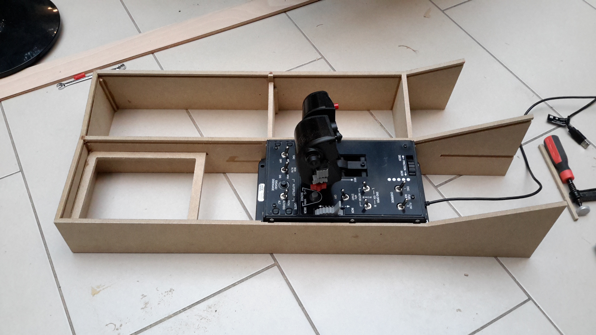
Finally started on the left console, all of it is designed around the fitment of the Thrustmaster Warthog Hotas unit, which is nicely in place. As you go along you learn from previous mistakes, so while the groove for the individual panel rails has been cut, I will put them in later so that I can space everything nicely. This is the last large part, from now on everything will fit to the existing frame and consoles. Machining the large pieces of MDF on my small router took a bit of work and planning, so I'm relieved to have those bits out of the way now, with just the outriggers remaining to connect the console to the main frame. I'll try and knock those out tomorrow, so I can concentrate on the remaining panels Cheers Les
-
Can you post the whole sketch, maybe we can see where the error is. The number of times I have had that or the ' XXX was not defined' errors....... Les
-
That's a possibility That's also a good point and it had occurred to me, but not very empirical! Les
-
I suppose the answer may be that the brakes are only used in benign situations - after landing, or in a straight line on approach. If they are not used anywhere else in the flight the need maybe lessened. But I always thought that having those big split brakes was one of the reasons it was so good at ground attack, that they could use them to help stabilise an attack approach, that type of thing. Like I said earlier, a lot of commercial aircraft have a proportional lever, so by its very position the pilot in command and the co-pilot could know where the brakes were . Well, it is what it is, whether I like it or not! Cheers for the answers Les
-
Thanks, but I still find the lack of cockpit indication amazing - what happens when it is dark? Cheers Les
-
Guys, I've never had to opportunity to sit in a real A10-C cockpit, much less have the chance to operate the controls, so I'm looking for some information and feedback. First up is the flap controls. I know that the Thrustmaster Warthog throttles I have does actually actually have that as one of the preset controls, but I struggle to believe that the real control is a tiny little switch tucked away behind the throttles. That it is three position switch, and that the flaps themselves are three position I accept, if nothing else because the in game behaviour is that. So where in the real aircraft is it? Google has not been my friend here! Secondly, the airbrakes..... all the aircraft I have worked with and seen have a speedbrake that is operated by a lever, which if you move the lever by 40% of its travel, the speedbrake deploys by 40%. However in game, you have a switch that deploys it and another that retracts it, with zero in cockpit feedback for the actual position of the brakes. Really? A major significant aerodynamic component with no feedback and no positive positional control? A proportional lever or multi-position switch is so much more logical, if nothing else because it gives positive in-cockpit verification of the position selected. The only in cockpit indication i have found is the 'SPEEDBRAKE SPEEDBRAKE' annunciation if I select takeoff power with them in a deployed condition. Speaking to the (admittedly civil aircraft) pilots at work, they say that it would be totally unacceptable to them as pilots, yet I cannot find anything online to indicate it is not as the game depicts it. So is it really like the game portrays it, or is there a different setup in reality? Cheers Les
-
Not a useless post at all, if someone has the same or a similar issue they can use this for reference or at least troubleshooting. Thanks for feeding back that you found the solution Les
-
Modular A-10C gauge controller for DCS Bios
lesthegrngo replied to lesthegrngo's topic in Home Cockpits
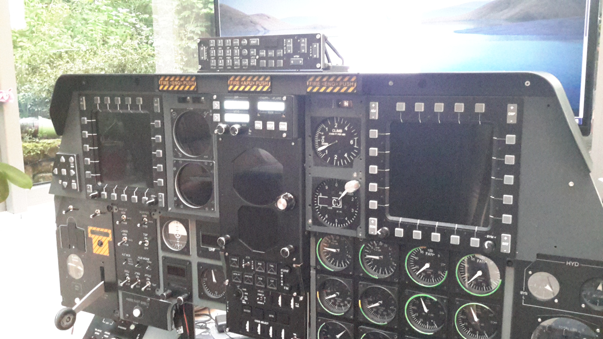
Thanks - this is what it looks like in place, and I'm very happy at how it turned out. The whole lot feels really solid and so all the switches on the dash have a realistic chunky feel to them. I envy you over there, I used to spend loads of time (and money...) in Bunnings when I lived in Melbourne. You also have Jaycar, plus loads of places to get aluminium extrusion, nuts, bolts, great modelling shops that sell all those tiny little gears, bearings, tubes, etc that would make all this soooooo much easier Cheers Les
-
Multiple LCD modules on one Nano - faint display
lesthegrngo replied to lesthegrngo's topic in Home Cockpits
Hi there, glad you like it The LCD modules are 0801 (8 x 1) character modules, these to be precise https://www.buydisplay.com/character-8x1-lcd-display-module-hd44780-controller-black-on-white I used them with some FFC adapter boards and PCF8574 boards from ebay, and my own PCB design. The sketch allows you to show all three LCD modules using one nano, and in fact you could also use it for the rotary encoders and buttons too if you wanted. I can give you all the design drawings in .dxf form if that is any use to you. My fascia was made from laser engraved and cut acrylic, the main backplate is from MDF and the PCB is a double sided one engraved on a little CNC router. The buttons are again laser engrave acrylic This is the sketch for the three LCD displays, remember you have to change the addresses of two of the PCF boards by shorting out two contacts (easy to do) #include <Wire.h> #include <LiquidCrystal_PCF8574.h> #define DCSBIOS_IRQ_SERIAL #include <DcsBios.h> LiquidCrystal_PCF8574 lcd0(0x27); // set the LCD address to 0x27 for a 16 chars and 2 line display LiquidCrystal_PCF8574 lcd1(0x26); LiquidCrystal_PCF8574 lcd2(0x25); int show; void onCmscTxtJmrChange(char* newValue) { lcd0.setCursor(0, 0); lcd0.print(newValue); } DcsBios::StringBuffer<8> cmscTxtJmrBuffer(0x1096, onCmscTxtJmrChange); void onCmscTxtChaffFlareChange(char* newValue) { lcd1.setCursor(0, 0); lcd1.print(newValue); } DcsBios::StringBuffer<8> cmscTxtChaffFlareBuffer(0x108e, onCmscTxtChaffFlareChange); void onCmscTxtMwsChange(char* newValue) { lcd2.setCursor(0, 0); lcd2.print(newValue); } DcsBios::StringBuffer<8> cmscTxtMwsBuffer(0x12b0, onCmscTxtMwsChange); void setup() { lcd0.begin(16, 2); lcd1.begin(16, 2); lcd2.begin(16, 2); DcsBios::setup(); } void loop() { DcsBios::loop(); lcd0.setBacklight(5); lcd1.setBacklight(5); lcd2.setBacklight(5); } Happy to give you any info you need Cheer Les