KLaFaille
-
Posts
291 -
Joined
-
Last visited
Content Type
Profiles
Forums
Events
Everything posted by KLaFaille
-
Ebay has literally thousands of parts for sale, you just have to sort through the garbage to find what you need, and hope you can get it for the right amount of money. That IFF I overpaid on, due to my own impatience and "gotta have it now" factor. The switches I found on a site that sells surplus .mil electronics and they were priced very nicely, especially considering MSRP from Honeywell is between 700-900 a switch! The biggest thing is the research involved, and sifting through all the garbage to find what info you actually need. That part of it isn't easy and it is incredibly tedious and frustrating at times. I swear I'll be able to recite NSN and MIL numbers back verbatim, in my sleep, soon. Red
-
5ET11 More bits came in today, 12 5ET11 magnetically held switches. Add 28 volts DC across pins 4 and 5 and the switch is held in the closed position. Remove the voltage and it snaps open automatically. It can be manually overridden, and with no voltage acts as an (ON)-OFF SPST. The A-10 uses six of these switches, four on the SAS panel for the Pitch and Yaw engage switches, one for anti-skid switch, and one for the Anti-Collision lighting switch on the lighting panel. 5ET11 (1 of 3).jpg by KLaFaille, on Flickr 5ET11 (2 of 3).jpg by KLaFaille, on Flickr 5ET11 (3 of 3).jpg by KLaFaille, on Flickr
-
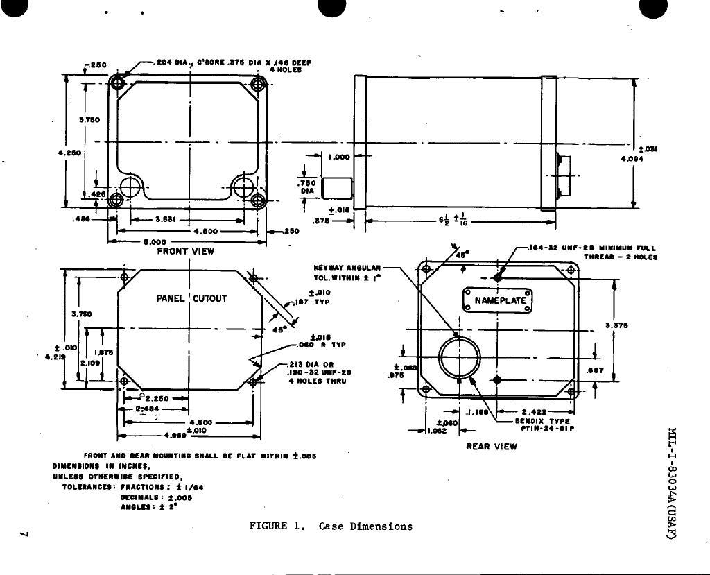
The dims he is referring to are for the ADI bezel & case that I had asked him for earlier. Red
-
HIS DIMS HSI DIMS for HSI called out for use in A-10A model. Red

-
New panel for the pit arrived today, a real C-6280A(P)/APX IFF Transponder Set. It's in wonderful condition, very little wear on the plate and knobs and everything works like it should, mechanically at least. I don't have the ability to test it electrically yet, but I have little doubts that it is electrically sound. The switches are really quite beefy, and please ignore the tape in the video, the locking action on the rotaries is very stiff and I needed a third hand. :) Attached are a bunch of photos for reference, the TM for the panel, and a video showing the positions of all the various knobs and switches. Follow the photos through for the full size images on my photostream. C-6280A(P)/APX IFF Transponder (1 of 9).jpg by KLaFaille, on Flickr C-6280A(P)/APX IFF Transponder (3 of 9).jpg by KLaFaille, on Flickr C-6280A(P)/APX IFF Transponder (4 of 9).jpg by KLaFaille, on Flickr C-6280A(P)/APX IFF Transponder (5 of 9).jpg by KLaFaille, on Flickr C-6280A(P)/APX IFF Transponder (6 of 9).jpg by KLaFaille, on Flickr C-6280A(P)/APX IFF Transponder (7 of 9).jpg by KLaFaille, on Flickr C-6280A(P)/APX IFF Transponder (8 of 9).jpg by KLaFaille, on Flickr (THANK YOU LORD for these being front release pins. I really, really, REALLY, don't like rear release pins. :evil:) C-6280A(P)/APX IFF Transponder (9 of 9).jpg by KLaFaille, on Flickr TECH MANUAL: http://www.tpub.com/content/radiosets/TM-11-5841-268-23P/TM-11-5841-268-23P0001.htm Enjoy, Red
-
Thanks Please don't go out of way, if you get to it that's cool, if not no biggie. I'll admit I'm pretty anal when it comes to things being as close to real as possible, I have keep in mind that a lot of this stuff ends up being semi-educated guesses or whatever looks as close to the real thing. It's tough sometimes when there is so little solid data out there. I did find a few documents that listed the ADI and HSI by part number as being installed on the A models. I'll send you that HSI print when I get home from work. You're right too, there would always be someone that would bitch!
-
The nice thing about the TM MFDs is they'll allow fairly easy interfacing with an A-10C bezel. I plan on hacking a pair of TMs for the controllers then source switches and make a custom PCB. Deadman, I spent about 5 hours last night researching the ADI and basically came up with if being an ARU-2B/A. Am I correct in that? Problem is, they were built to MIL-I-27193 which doesn't exist online that I can find so I couldn't find proper dimensions. If you'd be willing I'd appreciate it if you could share the dims of the case and the sizing and location dims of the mounting screws. I found the MIL drawings for the VSI case and HSI so I'm set with those and that's helping immensely with dimensioning the IP. There's a set of two ADIs on eBay now, but the seller wants almost 5k. Him and another seller (art in parts) are out of their gourds, art-in-parts wants hundreds for gauges that were clearly involved in crashes. I've found some good deals though, even if my wife doesn't agree! Red
-
I actually haven't decided yet. Ideally I'd like to keep the analog gauges analog but for the HSI and especially the ADI that's nearly impossible to do, so those will likely be a software implementation. The altimeter seems at least plausible to make analog. This however is a very novel and interesting solution to the ADI which you may have seen. http://www.viperpits.org/smf/index.php?topic=1062.msg87786#msg87786 (more info a few pages later also) Red
-
Excellent, thank you!
-
Hey Deadman, Can you tell me the Part No. on your Altimeter, or an MS No. if there is one listed? Thanks, Red
-
Thanks! I stumbled across a few .rar archives last night that contained a bunch of useful info in them, a couple of which are actually what I believe are your SW models for the A model IP, Duckling. I used a bunch of dims off that, adjusted to imperial, for reference on my IP and WAG'd the rest until the parts I have in the mail arrive. I was thinking of how I'll implement the MFCDs and what I'll do is hack a pair of Thrustmaster MFDs for the control boards and use switches sourced elsewhere and a custom PCB interfaced to them. That will give true plug and play functionality fairly easily. The control boards can be mounted either in the MFCD bezel or off board and connected via a header on the custom PCB. Red
-
Well I suppose I'll jump into the fray with my own take on a pit. I've never built anything like this before and I really don't know what I'm doing, but there are a bunch of people out there way smarter than me who I'm hoping won't mind having their brains picked now and then. :) Instrument Panel - 15MAR11 by KLaFaille, on Flickr Here's what I've come up with so far, after a few hours fiddling, for the Instrument panel. Right now I'm treating this as if it started out as a 39x18x2 inch plate of 6063 aluminum and it's being machined down. Once I get more concrete measurements I'll adjust it to a more economical and reasonable means of construction. For grins, a block of 6063 the size I mentioned would weigh 136.95 pounds and cost between $1800 - $2000 USD. That panel if it were machined right now as is, weighs 14.605 pounds. Talk about wasted material and cost! This will more likely end up regular sheet aluminum that I'll laser cut I'll add the steps for the instruments to. More to come. Keith - "Red"
-
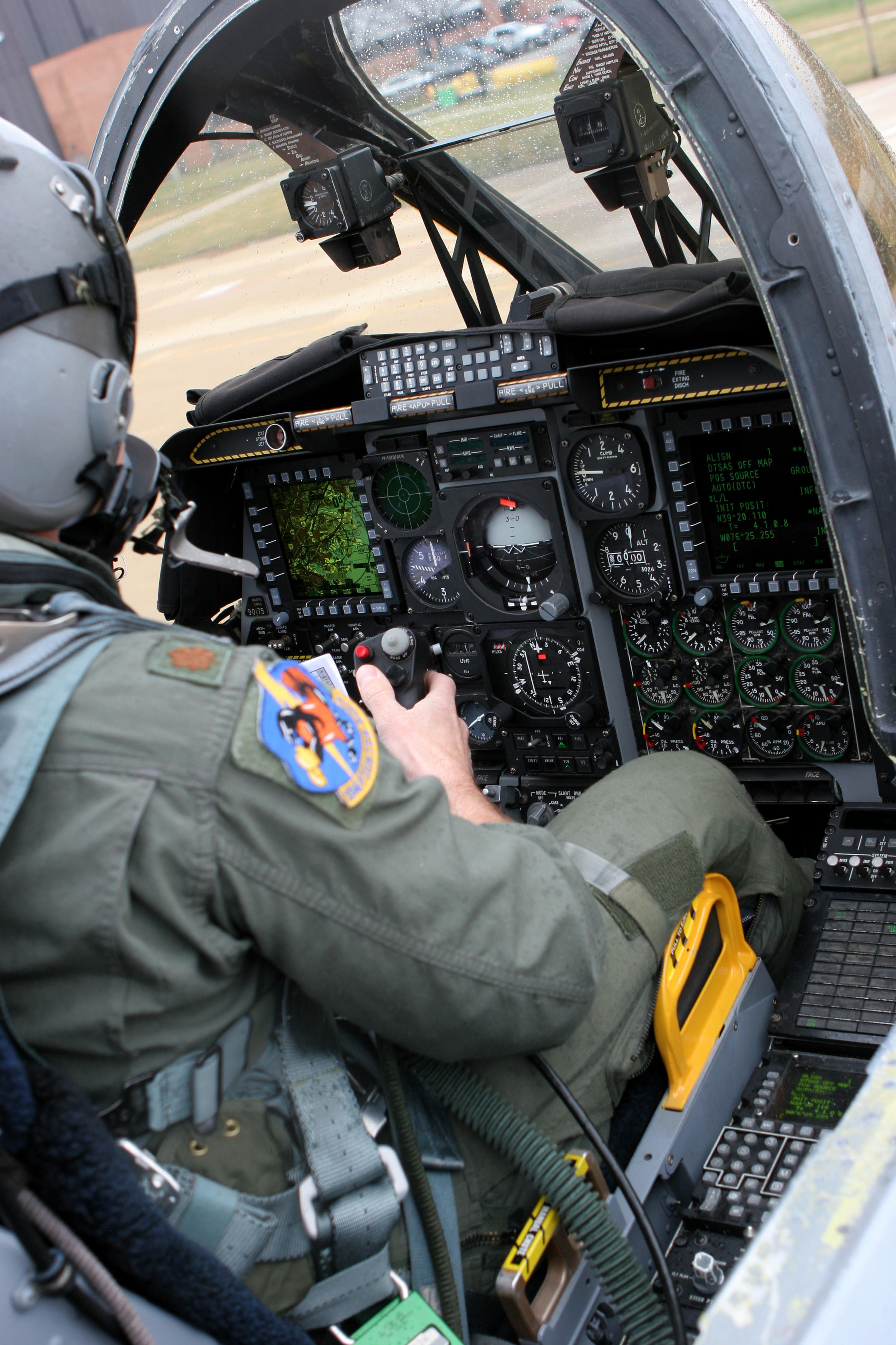
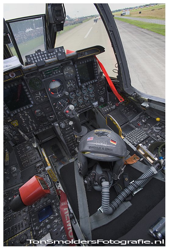
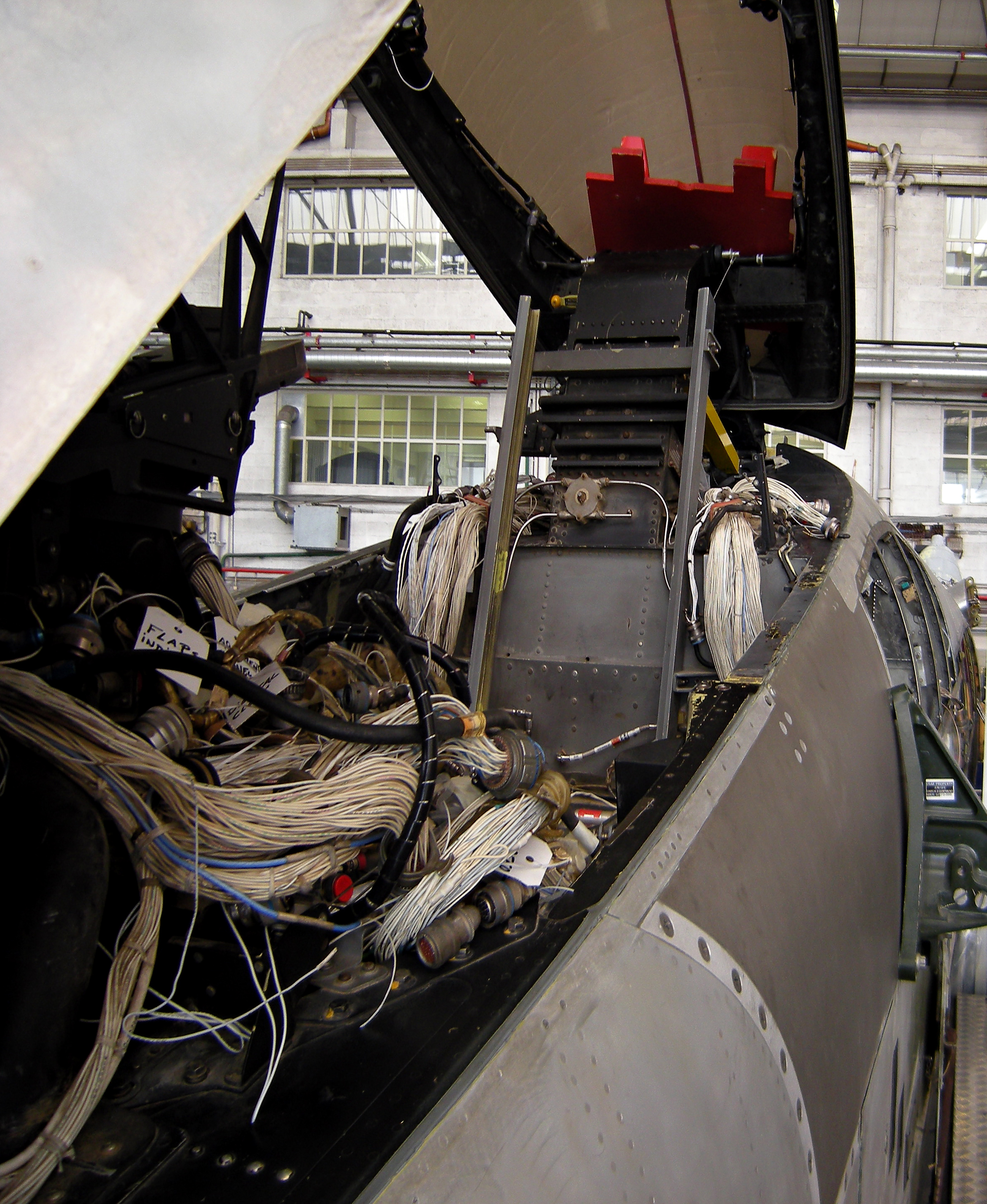
I just spent literally hours trying to find a decent shot of the right console, excluding the 17.6 trillion DCS screenshots, and had just found that exact photo that you had linked. That's how it should be. I think the problem is the CDU is actually much thicker than the regular light plates, but it looks level and flush in the sim so at certain angles in real life the labels would be blocked. Then again, they were there in earlier builds so I dunno. The first attached photo shows the thickness of the real CDU and the height of the switches and rockers, and for those that don't know, gives a good view of the different "steps" the various instruments are positioned in. Of course the CDU/EGI labels are just out of sight... The second image you can see the labels if you look carefully above the switches, but I was unable to find a larger resolution version of this shot. The last is just for grins and a look at the insanity that awaits. :D K
-
As an FYI, on the real AAP panel the EGI and CDU power switches are labeled such above the respective switch. Don't know why it's not in the sim... K
-
Good deal. I can swing the backplates myself, I'm drawing them up in SolidWorks and will get them cut locally. My plan is to set up each panel with all the electronics, get it wired, and add a connector plate attached by stand-offs with some sort of connector plug(dsub, Amphenol, Cannon etc). I'll make and run a wire harness from the I/O stuff and have a breakout to each panel. This way if something goes kaput or breaks or burns up, I'll just have to undo the panel from the console, disco the connector and be able to work it at the bench. I'd rather not to have to go digging around trying to replace, remove or rewire one bad component (which will ALWAYS be the least accessible :mad:) from the bottom of the console. I have to fix enough stuff like that at work to want to do it at home too! Anyways, looking forward to getting my grubby mitts on these panels. K
-
These are just the light panels or panel / backplate combo? I'm down for a Fuel Panel regardless, and UFC and CDU per our earlier convo. K
-

Finally Smooth Flying with these Graphic Settings
KLaFaille replied to toby23's topic in DCS: Ka-50 Black Shark
On a whim I tried changing the max framerate to 60 and the effects to 2, and I can confirm that it made a large difference in my frame rate. I'm not running a high end system by today's standards at all, 2.66ghz core 2, 8800gtx, win xp, and 1920x1200, so I was pleasantly surprised to see the increase. I was running avg 25 fps, down to 15-18 when the shkval was uncaged, now it's steady at around 45 to 50 and 25-30 with the shkval going. Thanks for the tip :) -
In explorer, go to x:\Program Files\Eagle Dynamics\Ka-50\BlackShark\data\scripts\Logbook Delete Players.lua Restart the game