K-dot-B
-
Posts
53 -
Joined
-
Last visited
Content Type
Profiles
Forums
Events
Everything posted by K-dot-B
-
 The last changelog has this: "DISS-15 control panel rolling counter inaccurate animation and stencil placement - fixed." but the counter still works the same as before. The Mi-8 did receive this change, and it is listed correctly in the changelog.
-
- 1
-

-
This is a nice update, hopefully the issue will be fixed soon. The rollercounter movement was originally reported here, if anyone's interested:
-
cannot reproduce damaged landing gear sinking into ground
K-dot-B replied to bephanten's topic in Bugs and Problems
Damaged gears do sink into the ground, a nasty surprise when trying to do pinnace ops. -
Update 24/12/24 - dust storm not working
K-dot-B replied to HR-Crumble's topic in Clouds & Weather System
Aww shoot... Well, thanks for looking into it, at least now I know its most likely a local issue. Since then I opened the mission file itself and there are some suspicious lines in it (names of seasons defined in multiple languages scattered in random places, weird), so maybe there's something deeply messed up with my game. I generally avoid mods for this reason, I only have SRS and The Way installed. Looks like major troubleshooting time for me -
Update 24/12/24 - dust storm not working
K-dot-B replied to HR-Crumble's topic in Clouds & Weather System
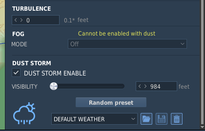
There is no option for dust thickness here
-
Update 24/12/24 - dust storm not working
K-dot-B replied to HR-Crumble's topic in Clouds & Weather System
Thanks draconus for helping me! It's weird, I do see the dust in your track. I also converted it to a mission file and I even see it when I launch that. However, when I create a new mission (or modify an old one) I never get any dust. Here's a test mission that I made. It's empty, literally just enabled the dust tickbox, yet I can't see any of it: dust_but_not.miz -
Update 24/12/24 - dust storm not working
K-dot-B replied to HR-Crumble's topic in Clouds & Weather System
For the life of me I can't get the dust storm to appear. I tried adjusting the dust slider, tried various maps, dates, weather conditions, ran a slow repair, nothing works. Is it tied to some graphics setting maybe? I was looking forward to using the effect, but it's a big disappointment so far. -
Can confirm it's fixed now, thank you!
-
@Flappie Hello, unfortunately this bug is still here. I made a fresh track today in the latest version. The Launcher Arm button fires rockets when pressed anytime after the first salvo is launched in the session, which makes it impossible to reset fresh launcher pods after a rearm. mi24_rockets_launcher_arm_issue.trk
-
fixed Petrovich Not Spotting Targets After Latest Update
K-dot-B replied to BoomBoom's topic in Bugs and Problems
Managed to reproduce it in singleplayer. The second track is an airstart and is much shorter. Edit: Interestingly, adding fog to the same exact airstart mission will allow Petrovich to see. mi24_petrovich_blind_9_11.trk mi24_petrovich_blind2_9_11.trk -
fixed Petrovich Not Spotting Targets After Latest Update
K-dot-B replied to BoomBoom's topic in Bugs and Problems
I tried it in signleplayer and I noticed some weird behaviour. If I turn off the fog entirely Petrovich becomes blind, but when I set some fog with finite visibility he starts spotting units around that specified range. Maybe the AI can't handle a visibility value of infinite/undefined. I'll test it more and post tracks later. -
It supplies the 36 VAC systems if both 36V transformers fail. In an emergency 36VAC is supplied from the inverter to the main and standby attitude indicator, vertical gyro no.2 and the "gyro correction cutout switch". Section 2-69 in the Cold War Air Museum's manual has a lot of info on this. I think it's mostly an emergency solution, and that's why it's never mentioned in normal operations.
-
Pressing the "launcher arm" button anytime after firing the first salvo will start launching rockets, regardless of weapon selector and safety settings. This will happen even after rearming the helicopter, so the issue makes it impossible to reset the new launchers. In the attached track I performed these steps: preparing the weapons on the ground, launcher arm works as expected, indicator lights appear taking off, firing a regular rocket salvo pressing the launcher arm again starts firing rockets landing and rearming pressing the launcher arm fires the rockets from the new pods, even after turning off the weapon safety switch bar in the front cockpit mi24_rockets_arm_issue2.trk
-
fixed Rockets can be fired when fire control switch is off
K-dot-B replied to bephanten's topic in Bugs and Problems
Worse yet, rockets can even be fired if the "Weapon safety switches bar" in the front cockpit is turned off. mi24_rockets_weapon_safety_issue.trk -
fixed Rocket burst length incorrect behaviour when using 4 rocket pods
K-dot-B replied to NumberTwo's topic in Bugs and Problems
Yeah, it's definitely not obvious at first. Hopefully these things will be better explained in the new manual. -
fixed Rocket burst length incorrect behaviour when using 4 rocket pods
K-dot-B replied to NumberTwo's topic in Bugs and Problems
No problem, I'm glad it works now! The launcher arming should work right after Petrovich starts turning on weapons (as soon as the pylon indicators light up, if you have them enabled), you don't even have to wait for the ready message. -
fixed Rocket burst length incorrect behaviour when using 4 rocket pods
K-dot-B replied to NumberTwo's topic in Bugs and Problems
I tried it and for me both S-5s and S-8s work just fine, so the issue is indeed fixed. Did you "arm" the launchers before shooting? I watched your track, you forgot to "arm" the launchers before shooting. (Arming is very misleading, from what I gathered pressing the button simply resets the rotary contactors that control the sequencing of rockets, so a better name would be "reset launchers". The indicators light up if the contactors are at their initial position.) However, I found that the "arm launchers" behaviour seems super bugged now. It works fine when used in a fresh spawn helicopter, but after using the weapons for the first time pressing the button again will launch every rocket from the pods, even if the master arm, weapon selector and the main weapon switch group in the front cockpit is disabled! Maybe it's just double binds for me, I'll investigate some more and create a new thread if needed. -
You know, I paid for the whole aircraft... This is why I like DCS, and especially the Mi-24. It's possible to go full nerd on a voltmeter, learn interesting things about the real helicopter and have fun flipping all the switches.
-
@Volator @admiki I stumbled upon some technical document that has a section on STG-3, the generator used in the APU, that says it is a "DC generator with shunt excitation". It also has a cross section of it showing that it is essentially a simple brushed DC motor. Since it is permanently attached to the APU turbine shaft (with "gear ratio 4" apparently) it is generating voltage as long as the APU is spinning, and so the voltmeter should be able to measure it. In game you can even measure its voltage while the APU is spinning up, which I found pretty cool. This was in chapter 13. of this document (I just translated it with google): GTD-350 Описание двигателя
-
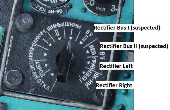
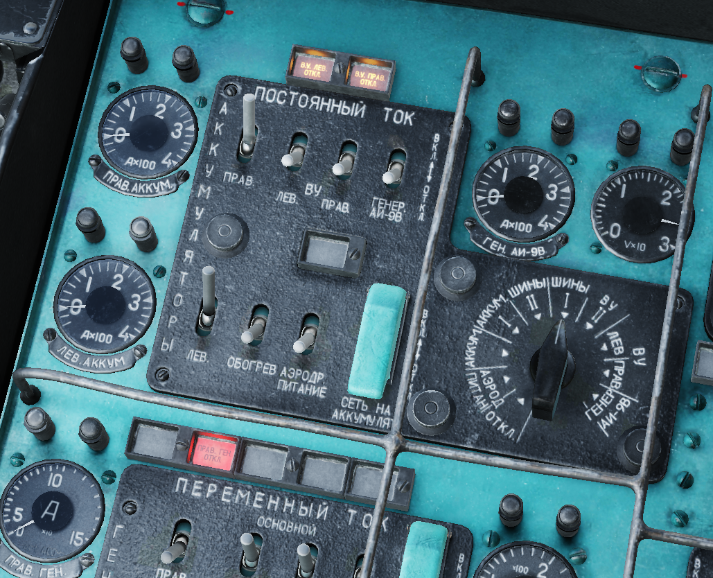
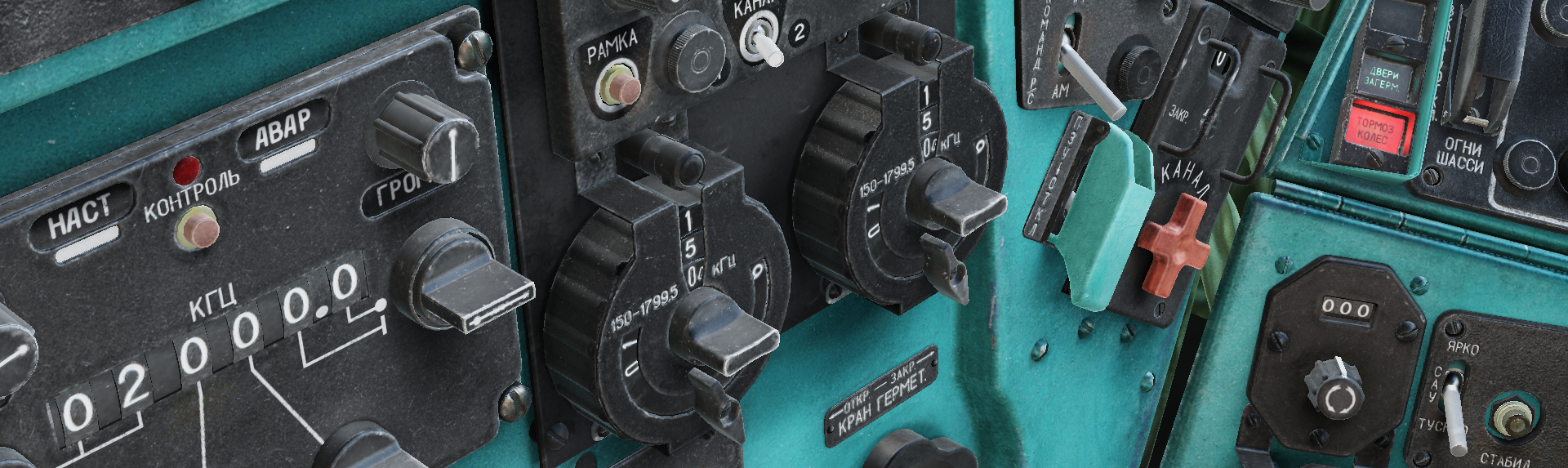
After my previous report on the DC voltmeter I kept on experimenting with the electrical system, and I found another problem. Issue: the last few positions on the voltmeter source selector appear to be shifted once clockwise (they show the voltage of the system marked to their left), and because of this the APU generator voltage can't be displayed. Someone already mentioned this problem before, but it appears to be in the wrong thread and I don't think it was ever reported: https://forum.dcs.world/topic/323016-ac-voltmeter-wrong-wiring/?do=findComment&comment=5171138 so I decided to make another thread with some fresh tracks. Track 1: The first track demonstrates going over the affected DC voltmeter selector positions and verifying the sources for each one. According to the CWAM Mi-24 manual, Rectifier Buses 1 and 2 automatically receive power from either rectifier, or through the guarded battery tie-switch from the batteries, APU or external power. I used this information for the test. Rectifier Bus 2: Shows voltage if either rectifier or the battery tie-switch is turned on. This behaviour corresponds to a rectifier bus. I suspect this position actually shows the voltage of Rectifier Bus 1. Rectifier Left: Shows voltage if either rectifier or the battery tie-switch is turned on. This is not the expected behaviour from a testpoint measuring a specific power source, so I think this is showing the Rectifier Bus 2 voltage. Rectifier Right: Shows voltage only if Rectifier Left is enabled. APU generator power: Shows voltage only if Rectifier Right is enabled. The last two cases seem to confirm the theory that the switch positions and the actual values are shifted once clockwise. This picture demonstrates the actual values observable at each position: Track 2: The "APU generator" position does not show the voltage from the APU. (Track 1 demonstrates that it actually shows the value from Rectifier Right) Lastly, these issues are probably related to the one in my previous report: https://forum.dcs.world/topic/349937-dc-voltmeter-incorrect-reading-for-rectifier-bus-i/ Mi_24_DCvoltmeter_shift_issue.trk Mi_24_DCvoltmeter_noAPUvoltage_issue.trk
-
reported Mi-8 DISS-15 Doppler nav rollercounter detail
K-dot-B replied to TasDozer's topic in Bugs and Problems
While we wait for this to be hopefully changed, I found that the rollover is correctly animated in the Mi-24 Greben control panel latitude window, when you change from north to south:
-
investigating DC voltmeter - Incorrect reading for Rectifier Bus I
K-dot-B replied to K-dot-B's topic in Bugs and Problems
I noticed this issue because while the voltmeter shows voltage on r.bus1, none of the consumers that are fed by it turn on. I tested this in a cold helicopter, only using the batteries as a power source. I used the list of systems powered by r.bus1 given in the CWAM manual (section 2-73.2) and turned them on one by one, first with just the batteries enabled, then with the batteries tied to the rectifier bus with the guarded switch. With just the batteries enabled, only the No.1 fuel pump and the formation lights turn on, however those are stated to be powered straight from the batteries in a different section. If the reading on the voltmeter for r.bus1 was correct, then things like the pilot and CPG fans and the CPG windshield wiper should be functional, but they are not. They only work if the interconnect switch is enabled and the rectifier buses are properly powered (the ARK-U2, Greben and SPUU require AC power as well.) If we assume that the developers implemented the electrical system correctly (which they appear to have), then the most likely explanation is that simply the voltmeter reading is incorrect. I believe the rectifier and battery buses are connected automatically only if the rectifiers are running and are able to supply power. It makes little sense to have a bus with big, nonessential consumers tied permanently to the batteries, especially if there is a manual switch that does exactly that. The electrical system is really fascinating with all its buses and interconnects, I'd love to see a schematic of it if you find one (and it's shareable ). -
Setting the DC voltmeter to Rectifier Bus 1 (шины ву I) shows voltage even if that bus is without power, as demonstrated in my track. I did some testing and it seems that the DC voltmeter selector is simply "wired" incorrectly, and it is probably showing the battery voltage. The actual simulation of the electrical system is correct, Rectifier Bus 1 only works if the rectifiers are turned on, or the batteries are coupled to the rectifier buses. Mi_24_DCvoltmeter_rectifierBus1_issue.trk
-
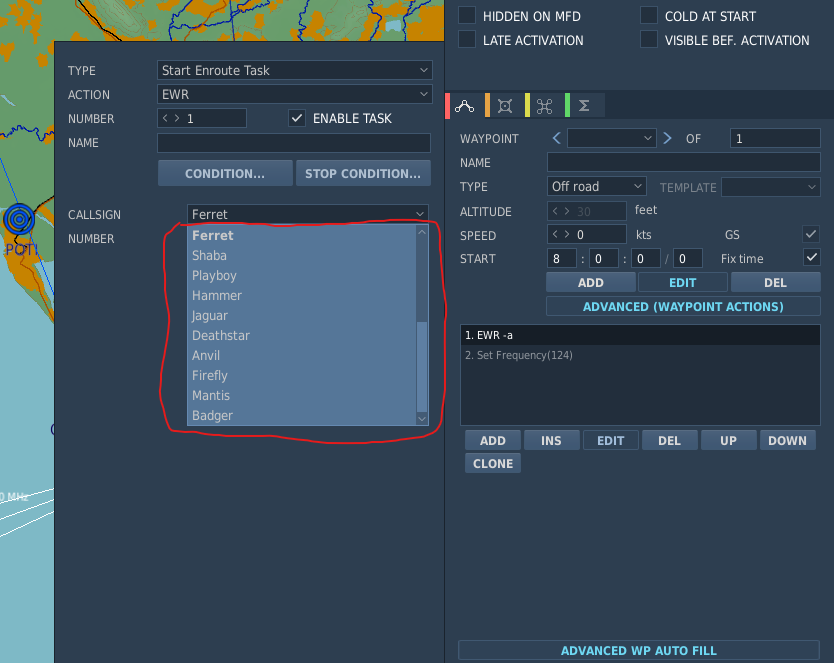
The last update (2.9.4.53627) seems to have broken some of the available callsigns for EWR units. I was working on a mission when the patch became available, and after updating I noticed that some of the EWRs I placed earlier stopped responding to radio calls. I found that callsigns from the second half of the list in the EWR task dropdown menu will not work in game. The EWR will not respond to radio calls, and the radio menu will show the unit's generic name instead of the callsign. I attached some screenshots and two tracks, one with a working callsign ("Pinpoint") and one with a faulty callsign ("Ferret"). Working callsigns: Broken callsigns: ewr_missing_callsign_correct.trk ewr_missing_callsign_faulty.trk
-
This must be a DCS-wide issue, because I've had the same thing happen with three way switches in the Harrier.