y2kiah
-
Posts
418 -
Joined
-
Last visited
Content Type
Profiles
Forums
Events
Everything posted by y2kiah
-
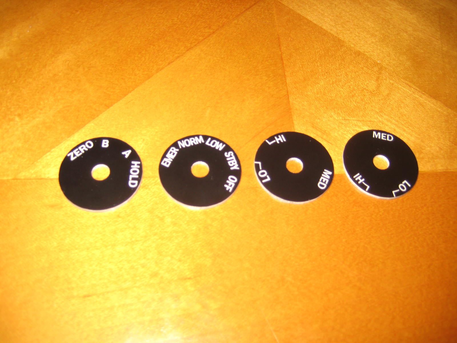
I have done engravings for the ENVIRONMENTAL Panel Flow Level and Temp Level knobs, it's no problem I can do more if needed, along with the ones for other panels. The edges would just need to be painted. Anyone who needs them can contact me directly, I will do ONE run and I won't do it until there are enough requests.

-
negative on the Helios. It would be a perfect solution for this, but for me part of the fun of this hobby is the build, and that goes for both hardware and software. I'm going to program my own HSI/ADI displays to be compatible with my pit communication system. The monitor is this one AT050TN22, I think the price has gone up That's the plan. I have to route an extended shaft around the bottom edge of the LCD, and mount the encoders behind the LCD. I will cut out gears to displace the shaft within the two cutout areas under each knob. It's complex, but the price I must pay for using actual dimensions. The ADI will be much simpler, because the LCD does not get in the way of the knob.
-
HSI I cut out my HSI bezel, here are some pics I still have to work out how I'm going to mount the screen and controller board behind the bezel, I'll probably mount them onto the instrument panel and just place the bezel over top.
-
Thanks for the information Deadman, it's a lot of money to buy these switches individually but very helpful to know for the future replacing cheap switches with real ones, one panel at a time
-
you will be able to make some nice panels on that, congrats!
-
I don't think you'll have any problems fitting that
-
Hi Linden, you are in luck, your increased size will fit in the pit with no problems. You will have about .5" of clearance on each side, but you may need to make the curvature on the lower, outer edge a bit sharper to clear the inner skin of the canopy sill. Or, you can choose not to skin that area. You will also have a problem if you decide to build the canopy frame AND swinging doors, because you will have no room for the pipe that supports the frame. Here's a screenshot of what I'm talking about. The dotted lines are where your two outer edges will be. Also check screenshot #2, behind the panel your supporting brackets that extend to the next rib will be farther out, so you will have some minor redesigning to do, but you can probably just do that by hand. The only thing to worry about there is that the bracket doesn't intersect with the hood. In general though, you will have no problems using a monitor/tv behind the panel, you can rest it directly on the center console along with the panel.
-
To say you "nearly miss" something is using miss as a verb. That paints a totally different picture than saying "near miss" which uses miss as a noun. It's a miss that is being described as near the target.
-
looking good Rocketeer, this will be functional in no time. I also went for the $2-4 switches, may slowly replace them over time as needed.
-
I'm not sure how it compares to Dimebug's in terms of dimensions, not familiar with his dimensions exactly. Mine is 53" wide, 64" long or 88" with the front extension. The aft rib is 37.5" high. I general I've tried to be as accurate as possible with a wood structure, so my plans would be very difficult to build without CNC cutting. I think Dimebug's are doable with hand cutting, so you may want to choose based on how you plan to make the cuts.
-
The latest files are not posted yet, the 3/4 birch plywood is actually .703, so I have to make some changes for that reason. A sheet of the stuff is $45. But, some pieces in the pit are actually fine to be made from MDF, which is .75" thick and only $30 per sheet. It's a toss up, create one set of plans with a mix and match set of parts? Create two sets of plans, one for each material type? Anyway, I've also been slow to post the rest of the pit because I had to tweak the rib shapes in the front sides and extensions modules due to this: It's a dimensionally accurate model of the C-model hood, measurements taken from a real A model hood and modifications made to the shape based on some very good photos of the new one that I got my hands on. I intend to cut out a positive in layered foam, sand down the corners to get the proper rounded edges, and make a plug to mold it out of fiberglass. You can see where they had to add bulges to accommodate the MFD cases extending forward. The DCS model does not include those details. How does it fit into my pit design? Like a glove... Notice the gap between the panel and the hood is present in the real jet. There is a strip of material attached to the hood with velcro strips to cover up the gap, but I've also seen plenty of photos of real jets where the gap is just left open. A cutaway shot of the supporting structure of the whole pit. I've left plenty of room for building a HUD system in later on, probably based on one of those mini short-throw projectors that are now getting pretty cheap to buy. Speaking of HUD, does anyone have a good source for actual dimensions and shape of the HUD? Otherwise, I'll have to eyeball it from pictures. The A-10 has quite a steep downward view angle, I think up to 20 degrees. Mine is based on more of an in-flight attitude rather than sitting on the ground, so it's approx. 15 to 17 degrees downward, can't remember which.
-
edited... discussion better in private
-
hey there slimheli, hold tight for a day or so, I'll be posting my latest and greatest drawing of the -C panel that you can base yours off of. Mil-spec accurate instrument cutouts, including the MFDs.
-
I'm going to build replicas of the AMLCDs, so I'll be getting 8.4" screens. I was suggesting 7" for the TM's you already have. Check vitrolight on ebay for screens, I've had good luck with them, quick shipping from China.
-
If I had to guess, $20K per unit? More? Of course we're talking about replicas here... 8.4" 4:3 screen to get full coverage of a 5x5 area. For your TM's, I think 7" is the common size to use. Go for the bigger screens if you plan to upgrade later, you can always cover up the outer area.
-
Correct, my MFCD's are designed based on the specs of the real A-10 units. Screen size is just under 5x5, bigger than the 4x4 F-16 screens. The TM MFDs will look small but will fit fine, just mod the panel for a smaller cutout. 5x5-amlcd.pdf
-
The maximum distance between outsides of the pedals is 20.75" minus some clearance. The minimum distance between insides of the pedals is 7 inches, plus some clearance. The ideal distance between pedal centers I have figured to be 14 inches. I ripped the electronics out of my old CH pedals and will hook them up to the diy pedals. Any commercial pedals including Saiteks mounted over the center of the base would most likely require a modification to my plans, at the very least to reduce the depth of the center pedestal. OR you could sink the base into the floor of the pit, and try to make it work that way. You always have the option to completely remove the center pedestal or make it a flat piece with no depth and structure to it, and figure out another way to mount the main instrument panel. There is absolutely no way I can design plans to work for 100% of the people that may want to build it. Part of the builder's responsibility is to hack it to fit their own needs and requirements and chosen hardware. Some guys have already pointed out that 3/4" plywood is actually under .71 thickness, while MDF is .75. So right there, I have a major gap in my design based on the material you would choose to build from. Some people prefer MDF, others prefer birch or oak plywood. Because of this, I basically need to have 2 versions of the pit to get a good tight fit between pieces.
-
Thanks! As Gadroc already said, these plans are not meant for hand cutting and I wouldn't recommend it. I had CNC cutting in mind from the very beginning, if I was going to design plans for hand cutting they would have turned out very different. I don't plan to release my panel files, but reactorone has released some in this thread.
-
Ok I'll make sure to fix them. The export script from sketchup is very basic, I thought there might be some cleanup needed, thanks.
-
JCook just make sure you explain the pieces that make up the throttle mount to the CNC shop. The lines on a dxf don't explain the depth of cut by themselves, so they will get it wrong if left up to them. Take a look at some of my screen shots and it will be clear how the pockets are cut, .5" deep, on those pieces.
-
I reworked the MFCDs according to the spec sheet that was posted a little while back, so it's now accurate to the real dimensions. I had to rework the front panel to fit the changes, so in case you're thinking about cutting the old front panel .dxf that I posted, don't! I will post the complete center section tomorrow.
-
Distributed training Prepar3D® simulation software
y2kiah replied to winchesterdelta1's topic in Chit-Chat
it's basically FSX. Based on "ESP" if you want to get technical about it. http://www.microsoft.com/presspass/press/2009/nov09/11-30WarfighterTrainingPR.mspx -
Yeah it probably varies by location and supplier. The birch I measured was the same thickness as the MDF at Home Depot. I think I need to take a caliper to it to be sure though. I guess a one-size-fits-all pattern won't be possible, I want to make sure my gaps are not too small for MDF so I'll stick to .75, if you want to modify them for thinner, I'll gladly post your modded files alongside the originals.
-
Right side has been posted to the original post. A little clarification on plywood thicknesses. I made a trip to home depot last night and remembered to do some measuring. The Birch plywood is a full 3/4" thick. The cabinet grade plywood is 23/32" which is close to .72, possibly what Gadroc is using. I'm planning to use the birch stuff, so I made the tabs exactly .75 wide in the cut layout. This will give a .03 oversize for the thinner ply, and a snug fit for MDF or birch.
-
sounds good, you thinking aluminum plate for the ribs mainly? pm me when you get a chance