y2kiah
-
Posts
418 -
Joined
-
Last visited
Content Type
Profiles
Forums
Events
Everything posted by y2kiah
-
Thanks guys. No I paid for time on a laser to cut and engrave everything, and as you can see the job isn't quite finished. My new CNC still isn't up and running, but I did some work on it recently because I really want to start cutting out the wood structure.
-
You may have noticed that I have an extra environment panel, AAP, and CMSP, and a stack of UFC's. If you want one, PM me. edit: oh, and an AHCP
-
Yes I do still want to release plans at some point, but I have been busy working on other things...:music_whistling:
-
If there are any two gauges in the pit where you're better off using LCDs, those are the two. Mechanical for any other gauge is very doable. Just my 2 cents.
-
nice work man, how does the spring force feel at the length? Does it recenter ok or do you think it will need supplemental springs?
-
Look again, the center section definitely rises above the level of the outer sections. They meet at the same level because the top of the real panel follows the slope of the dash. I didn't want to deal with the slope so I just made it flat all the way back. Once the dash goes on top it will look like they meet at the same level.

-
Nice! The yellow turned out really well, can I ask how you did it?
-
I'll have 5 small screens, MFDs, HSI, ADI and RWR. For the rest I will make replica physical instruments, but they'll be much lighter than real instruments so weight will not be an issue for me. The pictures do not show the additional support that I plan to have on the lower left and right of the panel. I'll have metal brackets attach the panel to the sides of the cockpit, to help stabilize it. I can sit on a simple box made from 1x1x1/8 aluminum angle bonded with JBWeld and I weigh 180lbs, so I don't think additional structure is needed for strength if you use real instruments, but more support for stability couldn't hurt. Here is a stripped down view of the structure that I'm planning to build. I just need a bracket to attach the lower part of the panel and it should be good. Altogether this uses just under 230" of aluminum angle, so that's 5 length's of 48" 1x1x1/8 angle which comes to about $27 plus shipping here.
-
BTW I have changed the top of my panel, probably a little less like the real thing but I think it will give the hood and "eyebrows" more room to mount. The center pedestal and the front panel mount are based on a structure built from aluminum angle rather than wood. I chose this to preserve the thin edges but still keep a solid structure. Plus aluminum angle is dead simple to work with... cut to length on a mitre saw, a little JBWeld between parts and you have a rock solid structure.
-
Here are the instrument risers on the front panel. Each layer is .25", so count the layers to get depth. At the thickest part, it is 1.75". Please understand that the width of the instrument mount (3.375") is not the same width as the instrument bezel. It is oversized a small amount to give the sidewalls more structure. As for the "two step" thing, I assume you mean the center section protrudes from the top by .25". When I reference photos of the cockpit, that's what it looks like to me, but it really doesn't matter you can keep it simple when you build and just make it flat.
-
no problem at all, glad to help. dimebug your kit is looking awesome, I like the way you mounted the front panel.
-
guys, I've updated my dimensions since I posted that picture a long time ago. They are not very different, but more accurate I believe.
-
looks and works great! It's great to see these pits start to come together, and you seem to be leading the pack
-
Hi guys, I actually do have quite a bit of progress to show, but no pictures at the moment. I've had all of my panels laser cut, except for the NMSP, MFD's and a couple other small panels that I have not designed in CAD yet. I still need to paint and engrave them. They look fantastic, the laser does an amazing job compared to a CNC router. I made 7 UFC's, 6 of these will be for sale. I made 3 CDU's, 2 will be for sale. If I still owe you panels, I will have them laser engraved because my new CNC is still not off the ground. I've started building my rudder pedals, so I'll also take some pictures of that progress as well. Vitrolight (on ebay) does not have a 4" 4:3 lcd available. Has anyone found a source for an lcd panel of that size that includes a VGA connection? This is needed for the CDU. Otherwise, a 3.5" would fit but the LSK's wouldn't align with the correct line of text on the display. There are some updates in CAD land too. Starting at the UFC, the case will be fabricated from 1/16 aluminum sheet. It will contain the circuit board with keypad buttons and back lighting, plus a microcontroller board. It will interface with the PC via ethernet. I chose this method because I want the master caution light to work, and I also want to be able to link the back lighting dimmer to the in-sim cockpit light knob. USB may seem like the easier choice, but as soon as you throw outputs into the mix, the obvious choice becomes ethernet. The knob on the side will also control dimming manually, and switch between sim-interface and manual dimming modes. Moving down, I've split the instrument standoffs into .25 layers so I can cut it out from one sheet of HDPE plastic and then bond the layers together. The ADI and HSI both fit a small LCD available from Vitrolight (I believe they are the Innolux 5.0" and 5.6" 640x480 models that they sell). The standoffs will also fit real instruments, but I don't plan to use any real ones. The knobs on these instruments are going to be tricky, most likely won't be able to fit a full encoder near the surface so I'll have to mount it farther back and put a narrow extended shaft through to the knob. Running the needles should be pretty straightforward though, either a servo or small stepper motor interfaced with an AVR microcontroller. The tricky one will be the airspeed with two needles, but I know what I have to do to make that work.
-
in HUD only view (ALT-F1) the entire view darkens to an ugly level, appears to be due to an HDR thing, I use the "normal" HDR setting
-
Love the parachute tube idea. There are a lot of opportunities to have fun with the build and do some unique things, once the primary task of building it and interfacing it are done. digitaljjd if you can write up a design since you seem to have experience building that kind of thing, that would be awesome. Getting in and out of the pit should be relatively easy due to its modular design. I have some pictures of the concept a while back but it's been a while, so here are some more. The two side consoles are hinged like a door to the fixed front portion of the sides. If things look weird remember some areas are still a work in progress.
-
lol, true but somebody had to figure those panel dims out first Deadman has already generously given a lot of good information here, just search the forums. Not everything will be spoon fed, sometimes you have to take what you know, and derive the rest from it. And yes, you definitely have to stop tweaking at some point and say this is close enough.
-
Fear not! The project is alive and kicking. In fact, the concept will become a reality when it is cut and built in the not-too-distant future. That's all I will say for now. Screenshots of the latest. You can see I've started to place drill holes on the sides, getting it ready for machining. I've also added a splash of color to distinguish between wood and metal parts. You can see above that I'm thinking about adding 3 or 4 inches to the length to get back behind the seat a bit.
-
What Gadroc mentions is one of the reasons I chose not to go with a UDP multicast solution, sending all data to all boards all the time. The "middleware" server in my setup will have a configuration file telling it which data needs to be routed to which boards. A lot less overhead on the network, and a lot shorter messages for the slow MCUs to parse. Having a central server also allows for loose coupling of export.lua and mcu firmware. Prevents export.lua from having to act like a server, listening for connections and whatnot. I also have an embedded Lua environment in the server where extra pit functionality can be developed if the sim that I'm interfacing with doesn't implement it. I'm thinking FSX and XPlane on that one. So Levinski, even if you switch to ethernet, I would recommend keeping the middle tier.
-
Semi-mobile in the sense that it won't be one solid piece in the end. It will be modular where each section can fit through a standard doorway. But, it will be stationary once everything is bolted together, it won't be on wheels or anything like that. The two side consoles will swing out like doors, with a caster on the outer edge for support. With a tall base I may have to rethink that part. Flim how big are you talking? I'll have a cutting space a little over 5'x2', just a bit longer than my first machine. Thanks guys I like the idea of a higher sitting position too. Nothing too crazy, maybe I'll just boost it up to the point where the seat is at the same level as a desk chair. I'll fool around with some designs to see what can be done.
-
Hi guys, I haven't made any progress on the pit since my last update. My first priority is to finish building the new CNC in my garage. Next, I have to finish some panels that I still owe. And finally, I will be able to start on my own pit. My garage got filled up with crap and it became impossible to work in that space. I finally broke down and bought a shed last weekend to house all of said crap... so now my garage can be a shop once again, finally. I have been stalking the forums though, getting jealous at all the progress others are making. As for plans, here is what I'll do. I'm going to build the left side console first. When I'm nearing the end of that I'll have a better idea of how the plans turned out, and what may need to be tweaked. I'll post the plans and a list of materials once they are fully thought out and tested. The rest will follow, of course. I'm still undecided on how tall I should make the base of the pit. The two choices basically boil down to 1) only enough to sufficiently mount the stuff that I need to mount to it, this turns out to be somewhere around 6 inches, or 2) much higher off the ground, provide more room for storage down below and raise the seat to a comfortable level for getting in and out. What is your opinion on this matter, guys?
-
The language is C++ with some limitations, anything "Arduino" in the language are just functions in their library
-
I always wondered what those little things were :thumbup:
-
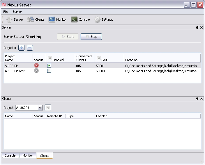
I've been using Arduino all along, I think Gadroc was using PIC or maybe someone else. My solution is about 2/3 finished. I have to stress test my firmware to make sure I don't run out of memory on the boards in practice. I'm doing some tricky things with dynamic memory that aren't exactly recommended on AVRs so I can pass configuration to the board from the PC and never have to re-flash the firmware when I make a hardware change. I also have to finish the server. Attached is a shot of how that is going so far. It looks better running on Windows 7, but it will run on XP, Vista and 7 and possibly Linux if I get around to it.
-
Alex, minor details aside you were right on, wasn't really correcting what you said. Somewhere along the line the notion of Lua being a file dump got out there, I was just trying to correct that. pitbldr, yep, you have it now. In function LuaExportStart() we open a socket for reading and writing with external programs. We can choose either TCP or UDP. If TCP, we must establish a connection with a TCP server that is running somewhere (most likely the same computer for most of us) and listening for connections. If UDP, there is no concept of a connection, so we can just start sending packets and listening for them. Then when the sim starts, function LuaExportBeforeNextFrame() and LuaExportAfterNextFrame() are called each frame. In them, we should do the following: 1) read any messages that have come into our open socket from the outside world. This is how messages from our hardware finally reach the simulation. 2) parse the message and do something with it, either performClickableAction() for some control, or anything else we may need to do. It's up to us to determine the message format. At a minimum, we need to know which control to set, and the value to set for the control. 3) get latest values from simulation for output to our lights, servos, stepper motors, etc. this is done with get_argument_value(). When we have all of our values, put together a message to be written to the socket. This will send the message out of the sim and eventually to our hardware. Polling for changes every frame can be a problem, we don't want to saturate the network with 60 messages per second when our hardware can't even respond that fast. This step can be done within LuaExportActivityNextEvent(t) every .1 seconds. So how does our hardware connect into all of this? For me, using the Wiznet shield on an Arduino, I can connect my interface card directly into the same TCP server that Lua connects to. So when I flip a switch 1) my Arduino firmware reads the input 2) it sends a TCP message to the server 3) the server forwards that message to the sim (Lua) 4) sim parses the message and does performClickableAction() this works in the opposite direction as well. This is just one way to do it and requires me to write the firmware, a TCP server running on the PC, and the export.lua file. If you use OpenCockpit cards, they handle the first two for you, and you just need to write an export.lua to send messages in the proper format. If you use Helios, even export.lua is written for you, so you need to write almost no code at all. Hope this helps.