jrsteensen
-
Posts
448 -
Joined
-
Last visited
Content Type
Profiles
Forums
Events
Everything posted by jrsteensen
-
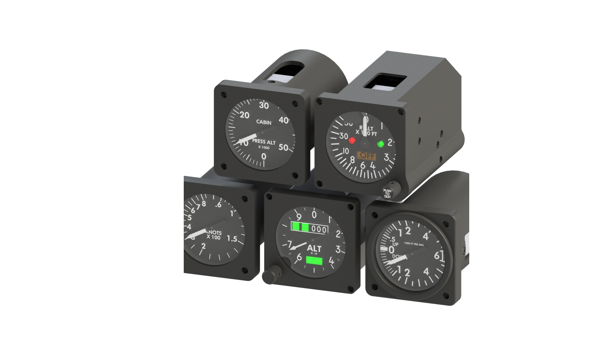
Here is the 2 inch instruments so far: (Small OLEDs for the dials in the altimeter. Flag in Radar Altimeter is fully functional/servo driven - also has a altitude indexer ring linked to the knob, with a continuous single-turn pot to track location. Push to test will also be functional.) I've decided to not make my own clock - instead I'll simply purchase a real ABU-11/A or similar off ebay for between $100 and $150. Going to be cheaper than recreating it.

-
This is a thread to capture wishlists from home cockpit builders for the F/A-18C module. Here are some of my minor ones that I am afraid may be overlooked. Output bits for throttle detents. Output data to drive autothrottle. (Perhaps as a position commanded/autothrottle activated/deactivated.) RWR Output as icon identification/azimuth distance. (Basically, I want the data to create a discrete RWR instrument, driven by an OLED display, versus just sticking yet another monitor behind the panel.) IFEI Parameters Output (Again, discrete parameter outputs so I can drive it with an OLED directly, versus mirroring output to a PC monitor.)
-
Impressive work! I have completed most my gauge designs for the F/A-18C pit, but the standby attitude indicator is definitely going to prove a challenge when I get there.
-
Agreed. Assuming you don't have a dedicated pit room that you can do a surround projection with multiple short throw projectors.
-
 Added a BOM for the boards. Lists both DigiKey and Ebay (Chinese) components. The cost savings on Chinese components is substantial, but do expect the occasional poor quality/DOA IC. For this reason, I always put a socket in for any IC that I'm using a Chinese IC for. (Lets me swap the ICs easily.)
 -
Starting work on all the gauges in the F/A-18C Cockpit. Looking for some proven designs for both continuous and non-continuous gauges. If I don't have to reinvent the wheel finding the perfect steppers, servos and air-cores, I'd appreciate it. Mind you, all my work will be released on a CC BY-NC-SA license. Couple questions off the top of my head: How do you RTZ (Return To Zero) Stepper powered instruments? Just backdrive them the maximum number of revolutions? Put a limit switch at zero and have the needle activate it? What steppers, servos, and air-cores are you using? In what applications? Here is a list of the gauges I will be doing: 3 Inch Gauges Standby Attitude (This one is gonna suck. Maybe OLED/LCD for it and the RWR?) 2 Inch Gauges Standby Airspeed Standby Altimeter Standby VVI Radar Altimeter Clock Cabin Pressure 1.875 Gauges HYD Pressure Battery Brake Pressure
-
Okay, posted on the link in the first post (or here) is the prototype representative boards. I ordered ~10x of each, and they should be on hand in two weeks. Boards ready are the ABSIS NANO, ABSIS MEGA, and 64 LED Matrix Accessory boards. Major Changes to the Nano and Mega: Eliminated LED matrix from boards. Broke required connections out to a 6 pin accessory header. Shrunk the sizes of all boards dramatically. Added NPN MOSFET to both boards, with 12V supplied, and controlled by a PWM pin. This will be to drive board backlights. (The vast majority of boards will not require the dedicated 64 LED Matrix board.) I will be adding accessory and specialty boards as I require them.
-
The Mega board has been posted. I have removed the MAX7219 and associated connectors, and instead routed the connection from the arduino to the MAX7219 and board power to a six pin connector. That way it minimizes the size of the breakout board, and LED as well as other additional support can be easily added modularly. Also, I hand routed the Mega board. Way cleaner. I will be doing the same removal of the MAX LED driver and hand routing the nano board. I may add a small IC to allow the capability to drive three 12V strips of LEDs for panel backlighting directly on the nano. Unfortunately, I already have 10x of the current Nano configuration on the way.
-
Got ~10x Nano PCBs on order. (Dirtypcbs.com - about 25 dollars shipped for "around" 10 boards.) Got the Mega board mostly reworked today. Still need to manually fix some traces. Once it's complete, I'll order 10x of those as well. For the RS485 Master board, I'll make a small PCB that will plug into the Mega - not a full shield, likely. All I need for a Master is to hook 3x MAX485/487s to it, and add the biasing to each bus, correct?
-
Some great input Spelmann. Thank you and it is appreciated. Fritzing's autorouter leaves quite a bit to be desired, honestly. I was considering beefing up the power traces, but I have to do it all manually. Also, there is no option I've found to tell it to prefer 90 degree bends in traces. I am concerned about cross talk across the traces. Sent from my SAMSUNG-SM-N910A using Tapatalk
-
Posted a revision to the Nano PCB. Changes: Removed flatcable connectors to include 7-SEG Outputs (That can be a breakout, if required.) Broke BUS into two polarized three polarized pin headers, including a ground line, with BUS IN and BUS OUT, as well as a resistor to terminate if required. Rearranged the board. Added a power passthrough to 3 pin header on top of board for auxiliary power tap for panel. (Solenoid relays, etc.) Fixed caps for ICs. (I think...not sure if autorouter did what I intended in the schematic.) Various minor fixes. Any input would be appreciated! Again, all these boards are released on a CC non-commercial share-alike license.
-
Ian or any others: What are the requirements hardware wise for a RS-485 Master? Simply a Mega with 3x MAX485/487s?
-
I don't know, but I imagine there could be some sort of case statement to do so. I also want to take it one farther and convert a number of items to a HID controller for non-DCS games. Looking forward to a real answer.
-
Where would the 480 ohm resistors link to to terminate the RS-485 bus? Found a good answer: 10 Ways to Bulletproof RS-485 Interfaces from TI Also, would there be an easy way to add LEDs to the bus lines so I can visually see when they are talking? (Kinda like the blinky lights on an ethernet connector?)
-
It was! Thanks for the input. Hoping to have the nano updated today. I'm also increasing the board width a bit. I want to be able to route all the jumpers together. Just was running out of trace room for a two layer PCB. (Oh, how I wish Fritzing handled four layer for a dedicated power and ground plane.)
-
Thanks for the input gentlemen. If I can shoehorn it onto the board I'll add a four pole DIP switch to convert J1, J2, J3 and a final position to disable MAX485/487 R0. When you say series vs decoupling caps, what do you mean? (Really not an expert on PCB design. Learning as I go.) I'll also add positions to terminate the bus near the bus connector. Sent from my SAMSUNG-SM-N910A using Tapatalk
-
Posting the first two PCBs for the ABSIS system for review - it will be a open source PCB/Hardware solution for interfacing with DCS-BIOS. Inside is an Arduino NANO and MEGA variant. WARNING: These two are currently untested. If a couple people could review them before I send them off for fab, I would greatly appreciate it. They are only posted in Fritzing format currently. Link: https://workbench.grabcad.com/workbench/projects/gcCsuFphr191MNK1hqtDKjijgQCBU_-ITV8Xu8nxLG-1SC#/space/gcIa1SQPPS0hxTytOzdhNwV22PVTUSm0S1dRDv-nNKRnPs Update from Page 2: Okay, posted on the link in the first post (or here) is the prototype representative boards. I ordered ~10x of each, and they should be on hand in two weeks. Boards ready are the ABSIS NANO, ABSIS MEGA, and 64 LED Matrix boards. Major Changes to the Nano and Mega: Eliminated LED matrix from boards. Broke required connections out to a 6 pin accessory header. Shrunk the sizes of all boards dramatically. Added NPN MOSFET to both boards, with 12V supplied, and controlled by a PWM pin. This will be to drive board backlights. (The vast majority of boards will not require the dedicated 64 LED Matrix board.) I will be adding accessory and specialty boards as I require them. NOTE: I FULLY expect these boards to have an issue or two, until I get to test them.
-
So, do I want to use steppers, servos, or a linear actuator to drive the autothrottle? (Looking for a little brainstorming here.) Primary concerns are they will remain linked while manually actuating the throttle, and cost.
-
SolidWorks.
-
What A-10c knowledge is applicable to be operating the F-18c?
jrsteensen replied to sc_neo's topic in DCS: F/A-18C
Actually, working on a throttle replica for my simpit. So, this is my understanding: Positions: OFF IDLE (Ground Idle) MIN (Flight Idle) MAX (Max MIL) AFTERBURNER Detent Definition: OFF <-> IDLE: Manual Finger Lift Activation IDLE <-> MIN: Solenoid-Activated Pawl. Activated (Up) when Weight On Wheels (WOW) and Launch bar retracted and arresting hook UP OR Weight Off Wheels MIN <-> MAX MIL: No Detents MAX MIL <-> AFTERBURN: Solenoid Activated Pawl. Activated (Up) when Weight On Wheels AND Launchbar Extended OR Arresting Hook Down. And here are their positions: -
Forgot some pictures from the WIP design.
-
So...Huey...kinda lost interest in. Getting back into F/A-18C pit with the impending release. My goal for this pit is to be able to build the entire pit with a X-Carve 1000mm and a Prusa i3 MK2S 3D printer and hand tools. One minor deviation from this is my throttle quadrant, which will be able to mostly be done by hand with a drill press, grinder, and sander. (Unless I can tweak my X-Carve to mill the .125 THK plate required.) The entire pit with models and drawings will eventually be released under a CC license. So far this throttle quadrant will function identically to the real throttle with solenoid driven Flight IDLE and AB detents, and provisions for attaching steppers/servos/linear drivers for auto-throttle, as well as exactly realistic locations for each throttle position. The only intentional deviation so far is friction will be set by the nuts on either throttle arm. Friction lever will be used as an axis. (I've gotten waaaaay too used to having zoom under my fingers.) The only thing I don't have so far is enough data on the throttle grips to replicate them well. If anyone else does, I'd really, really appreciate it.
-
Deadman, working on moving my stuff over to Flickr. Seems to work pretty well.
-
Buttons! Tell me about your design for keypad buttons...
jrsteensen replied to jrsteensen's topic in Home Cockpits
Great stuff Lynx. I've realized lately that we talk software, electronics, and dimensions to great lengths here, but sometimes we don't get into the nitty gritty of various techniques. Do you prefer illuminated tacts, or a standard tact with LEDs placed in close proximity for backlighting the switches? -
I have been doing integrated buttons (i.e. keypad buttons) a few different ways, but I've never really been completely happy with how they have turned out. I'm not going to go into detail on my methods yet, as I want to keep from contaminating responses for the time being. Few questions: How do you build them? How do you capture them into a panel? What tactile switches do you prefer?