jrsteensen
-
Posts
448 -
Joined
-
Last visited
Content Type
Profiles
Forums
Events
Everything posted by jrsteensen
-
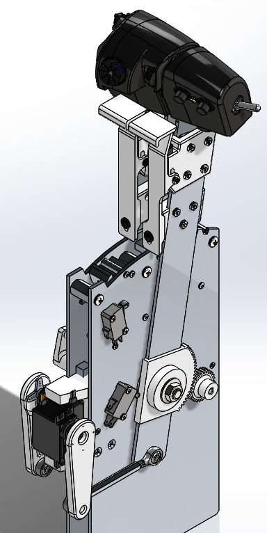
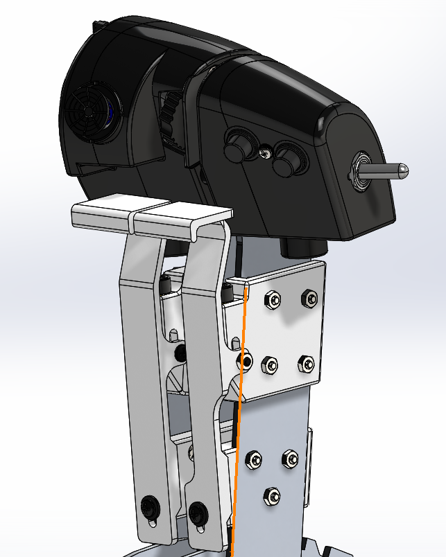
Been putting in some major hours on the throttle quadrant. Reworked a bunch of mechanisms, got the throttle grips done and populated with switches, and added autothrottle servos. Still working the actual mounting of it into the pit right now.

-
Been trying to join what? I sent out emails to everyone who made dev team applications yesterday. We dont have any plans available to the public yet. Sent from my SM-G960U using Tapatalk
-
Just a render showing the latest work. Did a redesign of the center pedestal, added ECS vents, added the parking brake handle and brake pressure gauge. Added paint to all the consoles.
-
Ah, yes. Sorry. Wasnt tracking. Its multiply the value by 1000, and in pounds per square inch units. Sent from my SM-G960U using Tapatalk
-
I'm sorry. I dont know what you are talking about? Sent from my SM-G960U using Tapatalk
-
We will be using the 10.1 for DDI and AMPCD. The extra is just hidden behind the console face. Sent from my SM-G960U using Tapatalk
-
Buydisplay.com has a large selection. Sent from my SM-G960U using Tapatalk
-
Awesome video! A few points of clarification in there. Thanks Greg and JAR!
-
So the center pedestal was bugging me. Went back and redid it. Added the lower ECS vents (though I didnt have a dimension for how far aft they extend. 1" seems to be the right ratio based on the very very few photos of that area I had.) Also reduced MDF screws by 2/3s. Sent from my SM-G960U using Tapatalk
-
[emoji23] Thanks man. Sent from my SM-G960U using Tapatalk
-
Figured these deserved some pictures.
-
Finished the Brake/Emergency Handle mechanism and the brake pressure gauge yesterday. Left console is component complete (minus throttle). Going to start working on modeling the PCBs and start dropping the electronics layer in. Goal on the left/right consoles is have them interface to the rest of the pit with a single USB cable and a single power connection. Sent from my SM-G960U using Tapatalk
-
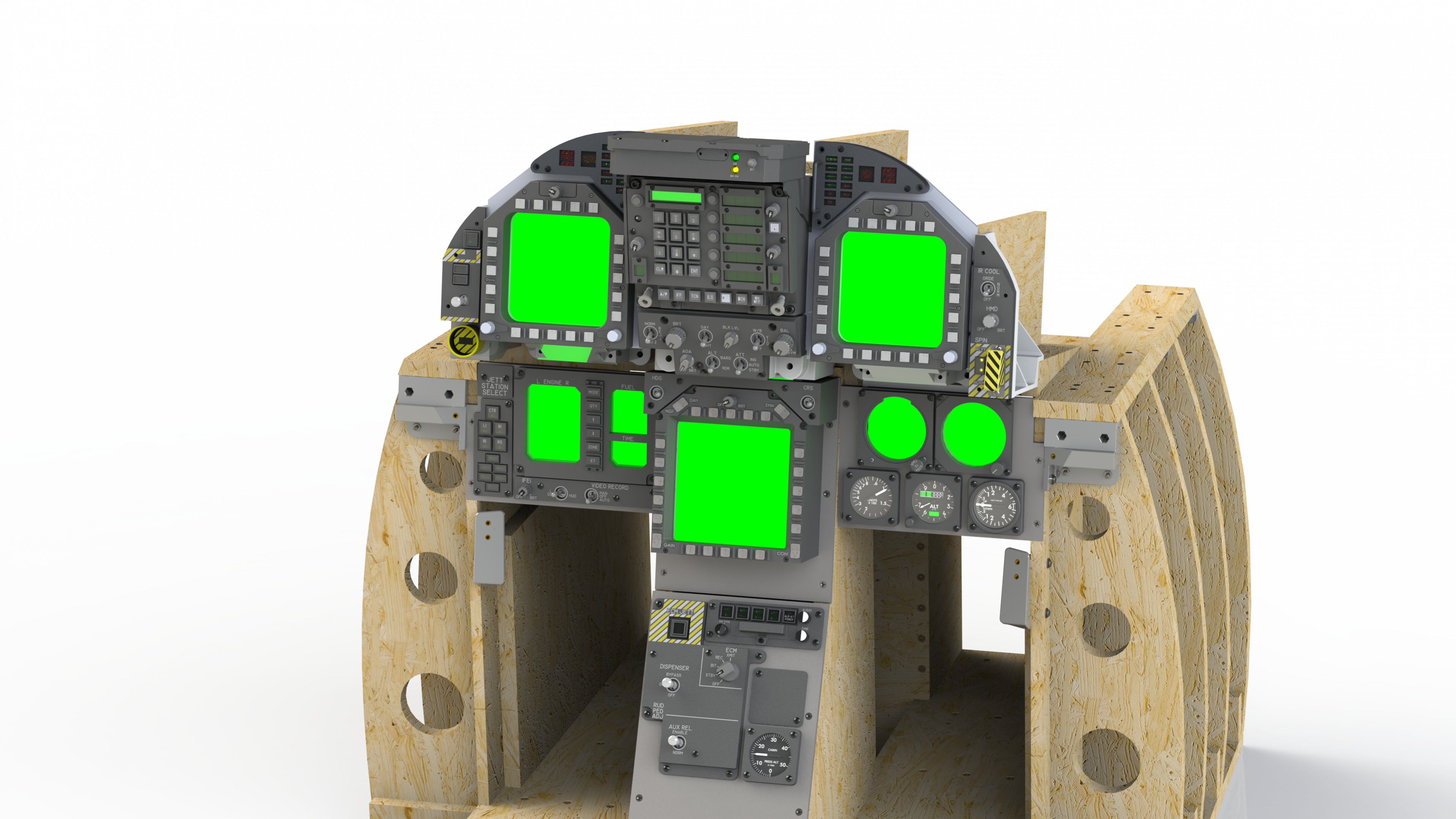
So been doing a ton of general cleanup and structural work. Still have quite a list on the mechanical side, but definitely progressing. Decided to do some high-res renders today. Ready to start work on the seat in earnest, but really lacking solid reference materials. I can extrapolate the major dimensions and control placement, but the rest of the seat may end up having to be fairly cosmetic.
-
Thanks! We'll certainly look into it, but its gonna take a whole lot to sway me away from being able to utilize DCS-BIOS for the project. Sent from my SM-G960U using Tapatalk
-
There's only two. The Mega and the Nano. I'll write up some datasheets eventually, but its really rather low on my priority list right now. See attached for what I've been working on the past couple weeks. It's coming along nicely. :music_whistling:
-
The ABSIS (Arduino Based Simulator Interface System) General I/O PCBs are basically a shield for a Arduino Nano/Mega that provides a convinent mounting, easy breakouts for wiring panels, an RS-487 bus, and converts three of the PWM pins to allow the user to select them between 5V and 12V.
-
I've invited Damien to post up here on it, as he can speak way more intelligently on it than I can. He is away from home for the next couple days, but will post here once he gets home and settled.
-
Okay, so this should be much closer to what ends up in the build. Hopefully it answers some questions. System Architecture.pdf
-
Primary display will be directly powered by the GPU. Our recent software engineer addition to the OH team (Damien22) has been coding up something to stream the outputs to the DDIs, AMPCD, RWR/SARI, and IFEI. It shows real promise and will only require creating a single virtual display adapter on the host PC. Preliminary testing shows almost no stutter, and only a tiny CPU overhead on the host PC.
-
Unfortunately, no pictures at this point. Didnt make it that far. I've been working on the system architecture for this a little to illustrate the electronics stack. Feel free to comment with any questions on it! On the structures side, left and right consoles are virtually done, lower instrument panel is 95% and about to start work on the upper instrument panel and the seat. None will be build ready yet, as waiting until I get a few odds and ends (component-wise) 100% so I can fit check everything in CAD. Sent from my SM-G960U using Tapatalk
-
Does anyone know what the indicator for the hook light is? Trying to locate it so I can get the dimensions right. Just realized I completely overlooked it in my model.
-
Okay, that is perfect. That will get me all the critical interfaces I need. Thanks! Sent from my SM-G960U using Tapatalk
-
We decided the 0603 components were going to be just too small for most people to comfortably hand solder, so we are redesigning with larger components. Sent from my SM-G960U using Tapatalk
-
DSP, Judging by the data sheet, that looks like exactly what I need. Do you know where I can find a drawing of it so I can make the CAD model? A preliminary search didnt turn it up. I was able to find the VID29 drawing though. Sent from my SM-G960U using Tapatalk
-
Looking fantastic WarHog. Your work continues to be an inspiration to me.