jrsteensen
-
Posts
448 -
Joined
-
Last visited
Content Type
Profiles
Forums
Events
Everything posted by jrsteensen
-
21 inches (~533.4mm) from between L console to R console where the seat mounts. The ABSIS shields will be released with our design, but it will ultimately be on the user to have them fabricated and to purchase the components and solder them together. Due to quantities required, we are thinking about selling a run on the site since the min buy QTYs will be greater than what you need for assembly. (More along the lines of organizing group buys to drive economies of scale and QTY discounts.) Nothing for sure on that front though.
-
Honestly, they simply arent out there for less than several thousand dollars apiece. We went with the buydisplay.com TFTs, 3x 10.1" (PN ER-TFTV101A1-1) and 2x 7" (PN ER-TFTV070A1-6). 10.1s drive DDI/AMPCD, and the 7s drive the IFEI and the SARI/RWR. Sent from my SM-G960U using Tapatalk
-
 Just got out of a dental surgery. Ping me again on Monday. Kinda outta it. I can get you a STEP. Sent from my SM-G960U using Tapatalk
 -
That's a nice pedal - never seen that before. We did them based on the real F/A-18C pedals, and they are designed to fit into the footwells of the OpenHornet cockpit. Sent from my SM-G960U using Tapatalk
-
Some in the pedal holes, but probably not required. Sent from my SM-G960U using Tapatalk
-
Everything else was default on the Prusa i3 MK3. Sent from my SM-G960U using Tapatalk
-
Shapeways is your ticket. I'd print them out of PET or ABS. Sent from my SM-G960U using Tapatalk
-
Hey all! Just wanted to push these out where more people might see them. Here is the release of our pedals for the MFG Crosswinds. It's about a 15 hour print per pedal. Hope you guys enjoy them - they install on your Crosswinds pedals with your stock pedal HW. Printed .20 layer height at 30% infil. They are licensed under a Creative Commons Attribution-NonCommercial-ShareAlike 4.0 International License. https://workbench.grabcad.com/workbench/projects/gcCsuFphr191MNK1hqtDKjijgQCBU_-ITV8Xu8nxLG-1SC#/space/gcIa1SQPPS0hxTytOzdhNwV22PVTUSm0S1dRDv-nNKRnPs/folder/3132395
-
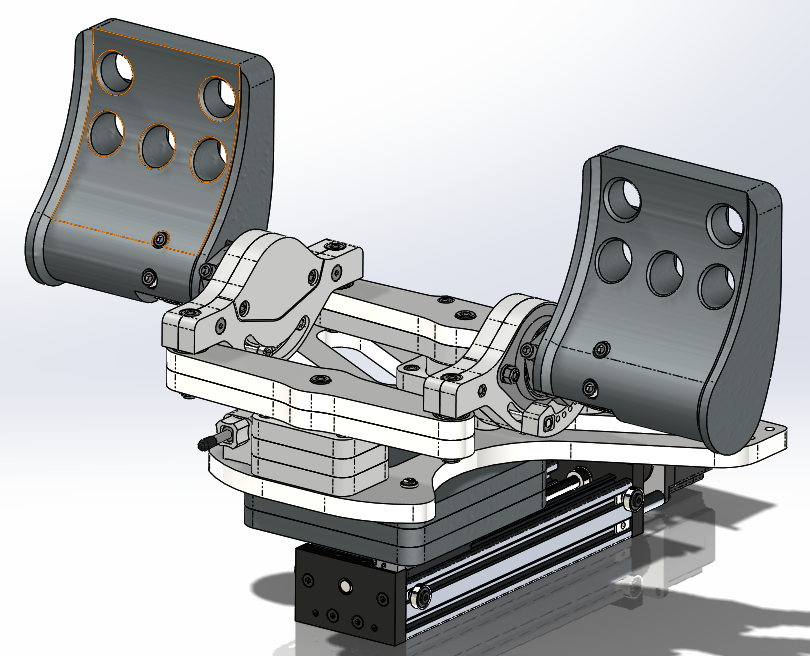
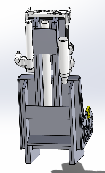
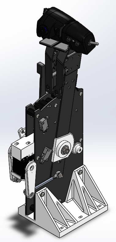
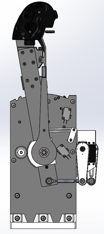
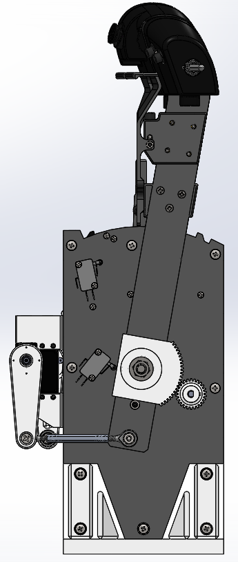
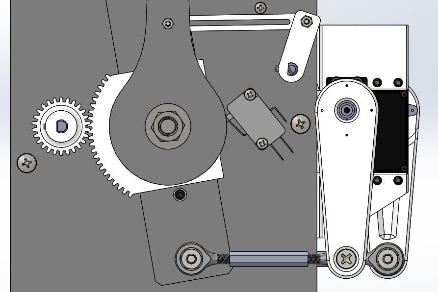
So I'm redoing the rudder gantry. Decided I wanted a more mechanical solution, but will still use a solenoid to unlock the FWD/AFT adjust of the pedals to reduce the complexity of the linkages.
-
No problem! Yep. Down here by Fort Huachuca. Sent from my SM-G960U using Tapatalk
-
IIRC he said he used .20 layer height at 30 degree infil. These were a test print of PLA, so not sure how they will hold up - I'll probably print them out of PET. Sent from my SM-G960U using Tapatalk
-
Here they are installed on his pedals. Sent from my SM-G960U using Tapatalk
-
I couldnt have done it without RandomTroubledMinds work on the pedals and his meticulous work on reference models for me to work from. Speaking of, here is the release of the pedals. It's about a 15 hour print per pedal. Hope you guys enjoy them - they install on your Crosswinds pedals with your stock pedal HW. https://workbench.grabcad.com/workbench/projects/gcCsuFphr191MNK1hqtDKjijgQCBU_-ITV8Xu8nxLG-1SC#/space/gcIa1SQPPS0hxTytOzdhNwV22PVTUSm0S1dRDv-nNKRnPs/folder/3132395 Sent from my SM-G960U using Tapatalk
-
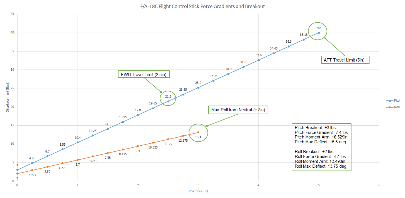
Hey guys, been compiling data on the stick and came up with this chart as I was doing some calculations. Our intent is to capture the real force gradients and breakout forces on the stick.

-
McG: Center Pedestal is 7.8in [198.1mm] wide. Total footwell width is 23.1in [586.7mm]. Sent from my SM-G960U using Tapatalk
-
No. You should be able to design a platform for your specific pedals pretty easily. I think the TM pedals will be too narrow to clear the center pedestal however. Sent from my SM-G960U using Tapatalk
-
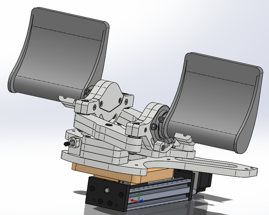
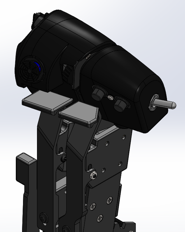
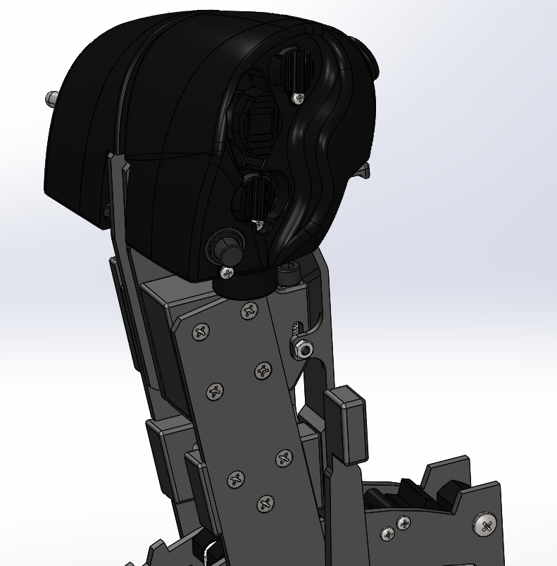
And the pedals are done, and integrated into the pit. No mods required to the Crosswinds. They have about 7 inches of electric adjustment, then can be manually slid back and forth on a rail and locked in place so you can place the CL of that 7 inches wherever you need to.
-
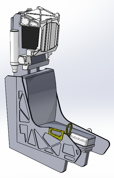
Well, finished up the seat this AM. Well into the rudder pedals and powered linear actuator carriage adjustment mechanism. This is using the MFG Crosswinds. You can see the carriage, and the reference pedal I'll be using to design a pair of 3D printed pedals for this thing. Oh! Prime example of why we don't release anything yet - I had to remove 3 inches of material from the structure of the lower console to accommodate the pedals at full aft adjustment.
-
Ultimately, no. While still designing, everything is subject to change until the release candidate is ready. I've ran into several situations that resulting in some minor and some major adjustments to other assemblies while designing other components. It's a bad idea that will result in people having to rework things multiple times. Best just to not paint ourselves into that corner.
-
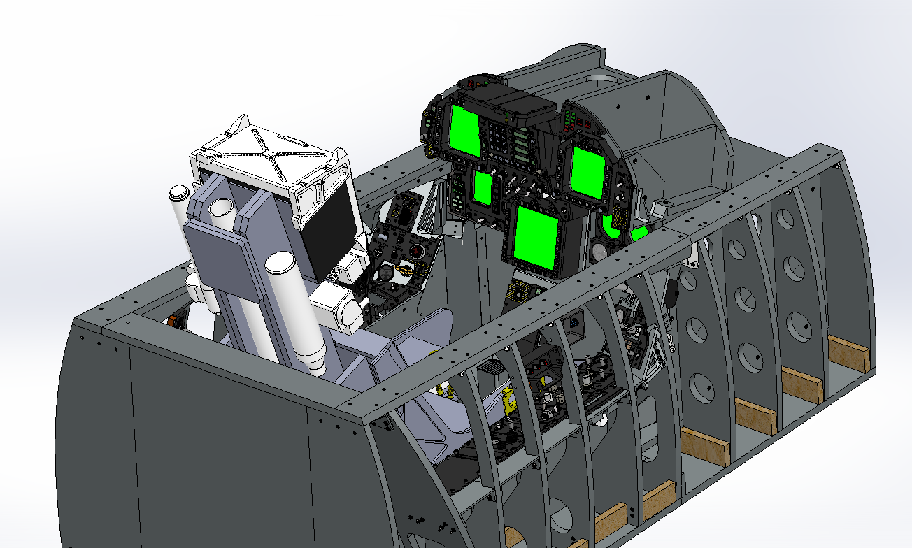
AJ: Unfortunately, the panels will not be back-lit this iteration. Backlighting creates an order of magnitude of complexity and cost and we decided that backlit panels are something we may do in a future iteration. That said, the electronics are capable of supporting PWM backlighting. Here is an excerpt from our requirements document detailing the panel construction: Badger: Here is the footprint of the pit: (NOTE: This does not include any external visuals or other accessories you may utilize in the installation.) Length: 71.2in [1808.5mm] Width: 34.47in [875.6mm] Height: 42.61in [1082.3mm]
-
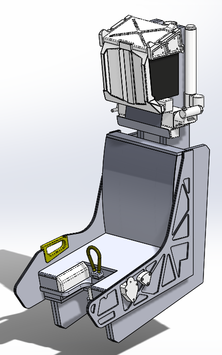
Been working the seat pretty heavily. Conceptual model is mostly done - now I have to finish designing the various mechanisms, the seat arming lever, and fastening everything together. And just to show how far we are....
-
Just wanted to add screen caps of the final iteration of the throttle quadrant. Work on the seat is in full swing, and really excited about what this comes out to. Unfortunately, reliable reference material has been hard to come by, so it will be "ish" at best unless some first hand sources become available.
-
We acquired a real inboard grip and were able to extrapolate the outboard grip between that and several dimensional (but not complete) drawings we had. Sent from my SM-G960U using Tapatalk
-
Throttle Quadrant is complete - redesigned the servo mounts, and made it a stand alone installation into the console - some significant redesign of the forward internal structure of the console was required. Also, redesigned the fingerlifts - they are not going to be fun to print, but unfortunately the best I can do. I MAY machine them out of aluminum just for fun. The cover plate for the console is pretty different than the real one - this was necessary because of the build requirements of the throttle quadrant. Just no way around this without making the throttle arms more like the real one which will take a full machine shop to make.
-
Thanks all! Really excited about this so far - likely the most complex part of the pit so far. No exploded views yet. If I get bored and want to take time from accomplishing the current stuff, I'll make em, but otherwise not until the design is done and it's time to start making drawings and the BOM. Sent from my SM-G960U using Tapatalk