tavarish palkovnik
-
Posts
485 -
Joined
-
Last visited
Content Type
Profiles
Forums
Events
Everything posted by tavarish palkovnik
-
Why not, of course until request is about motor which is with at least some background You know, finding what could be inside of some “pipe” not having some at least basic parameters of that motor, would be nothing but guessing about with what that pipe could be stuffed, and number of such combinations is endless
-
Another one from pallet of these old motors, Genie AIM-2 rocket, motor which I didn't find on internet presented in drawing showing it in complete, only segments. But because there are a lot of very helpful inputs, this motor is actually one easy to strip down

-
Dimensional features: Motor length 723 mm Motor diameter 163 mm Chamber length 492 mm Chamber diameter 159 mm Chamber wall thickness 2 mm Weight features: Motor weight 19,5 kg Propellant weight 12 kg Boost propellant weight 6 kg Sustainer propellant weight 6 kg Propellant data: Type TP-L-8006 (T-27) Composition: 78% AP, 2% Al, polysulfate binder Propellant density 1738 kg/m3 Heat ratio k=1,22 Burning temperature 3105 K (at 69 bar) Exponent in burning law 0,4 Burning rate (at 69 bar) 12,7 mm/s Molar weight 28,5 kg/kmol Output: Thrust in boost 2005 kg Thrust in sustain 288 kg Boost time 0,63 sec Sustainer time 4,09 sec Total impulse 2449 kgs or as per other source Thrust in boost 2079 kg Thrust in sustain 277 kg Boost time 0,61 sec Sustainer time 4,25 sec Total impulse 2458 kgs ..... so more or less everything is available in open sources, except how that motor looked like inside, what was propellant grain configuration to give this output and that is what I'm interested for @Harlikwin nice to hear that
-
I know this is boring to most of you but nevertheless 12-point dendrite converted to 10-point dendrite, from fabrication point of view this could be more convenient design and it still gives output as needed
-
But I like to post and write exactly here There are no much questions about game, no complaints so everything is just fine Motors are my fun and I like to have it on paper, I want to know how they look/looked inside. Don’t forget that here on this forum some of motors have born in picture, motor images which you can’t find easily on internet, if at all One of those motors which are not available in picture is motor of AIM-26 but here it is, this is that motor in scale That one was easy but interesting to me because it shared same propellant as motor in AIM-4F/G with which I still struggle, and this is some fifth or sixth or perhaps seventh-eighth version until now Awkward design and concept but it gives targeted output based on collected inputs from various sources. It looks strange, but who knows maybe it was really that way, not first American motor which surprised with shape when showed itself with time
-
Unless I made some crucial mistake, I hope I didn’t, this is how propellant grain in Mk78 Mod.0 motor should looked like Concept of Hawk’s motor like said, trick is in usage of exactly same propellant in sustain stage (ANP-3196-1), propellant which can burn stable at very low chamber pressure and which burn very slowly. Without aluminum and filled (significantly) with burning catalyst, in this case not with oxamide but with nitroguanidine. Air launched motor which if I’m not wrong has the biggest difference in thrust between boost and sustain stage, of all. Indeed unique one.
-
Нет, это больше чем просто игра
-
I’m trying to reconstruct majority of motors involved in Shrike missiles and currently three of four are clear, early Mod-s of Mk39, Mk39 Mod.7 and Mk53 Mod-s. Clear and fully understood, all belonging to AGM-45A. Mk78 of AGM-45B is still in progress, quite of puzzles are collected and close to be puzzled together. Interesting motor this could be, one of several coming from US kitchen in form which can come only from this kitchen, although not exactly unique because few motors share similar concept. Of course, only if my thesis is correct. I’m looking for, if it exists, any reliable data source saying something about burn time of this dual thrust motor in AGM-45B. This will help in puzzling, in placement of boost and sustain propellant layers (of grains) one to other respectively. Momentarily I’m more on layers, concept similar to grain in Hawk’s rocket motor, at least and after all, same or very similar propellant grades these two motors share
-
Changed, revised, modified and supplemented cross-section collage. Motor XM46 (AIM-4F/G) is still under question, this could be form, while rest of motors are more or less confirmed
-
Don’t forget these values in most cases are given for ratio 69:1 bar or 1000:14,5 in psi. Chamber pressure vs ambient pressure, with full expansion of gases, and without losses in divergent zone of nozzle Same as Russian motors and propellants, only in ratio 40:1 which is Russian standard
-
Could somebody help to solve one dilemma about Sidewinders Seems like there are three different propellant grain forms through history of Sidewinder motors -> -first one is internally burning star (most probably 8-point star) and this grain was in AIM-9B -second one is internally burning 6-point star with cylindrical exit and nozzle was submerged. This grain form was in motors of AIM-9C and 9D (CTPB based composite) also in AIM-9L but with double based propellant. And most probably in few more Sidewinders, I guess AIM-9M is in this group -this is third grain form Internally burning cylinder with slotted aft end (most likely 6 slots). This same grain form is in AIM-9X but in that motor nozzle is externally positioned and with jet vanes included. Question is…what Sidewinder before 9X model could have motor with such grain configuration? Nozzle is still submerged as in Mk36 series and I doubt this motor remained in 36 nomenclature. It is some AIM-9 between L and X but I don’t know which one it could be
-
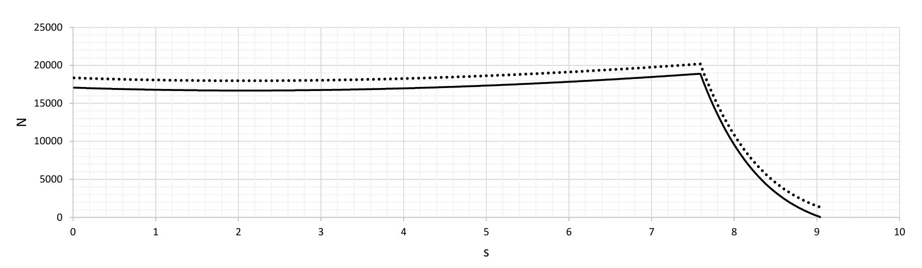
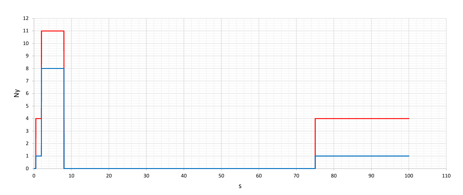
Nozzle is significantly expanded so altitude makes significant role WPU-6/B Sea Level and 10km WPU-16/B Sea Level and 10km
-
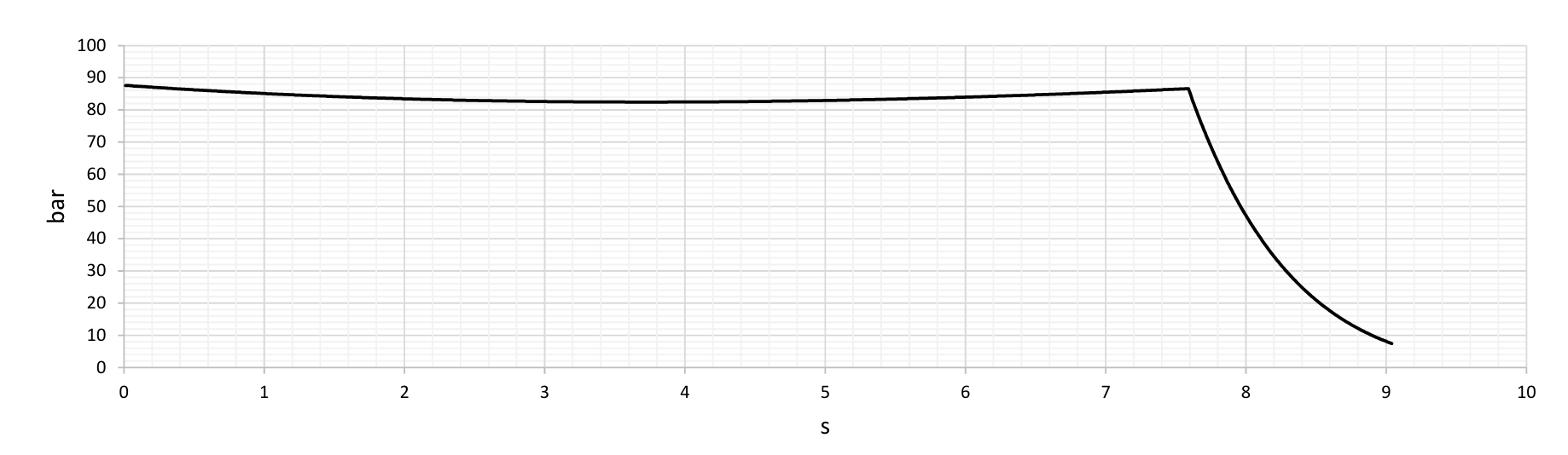
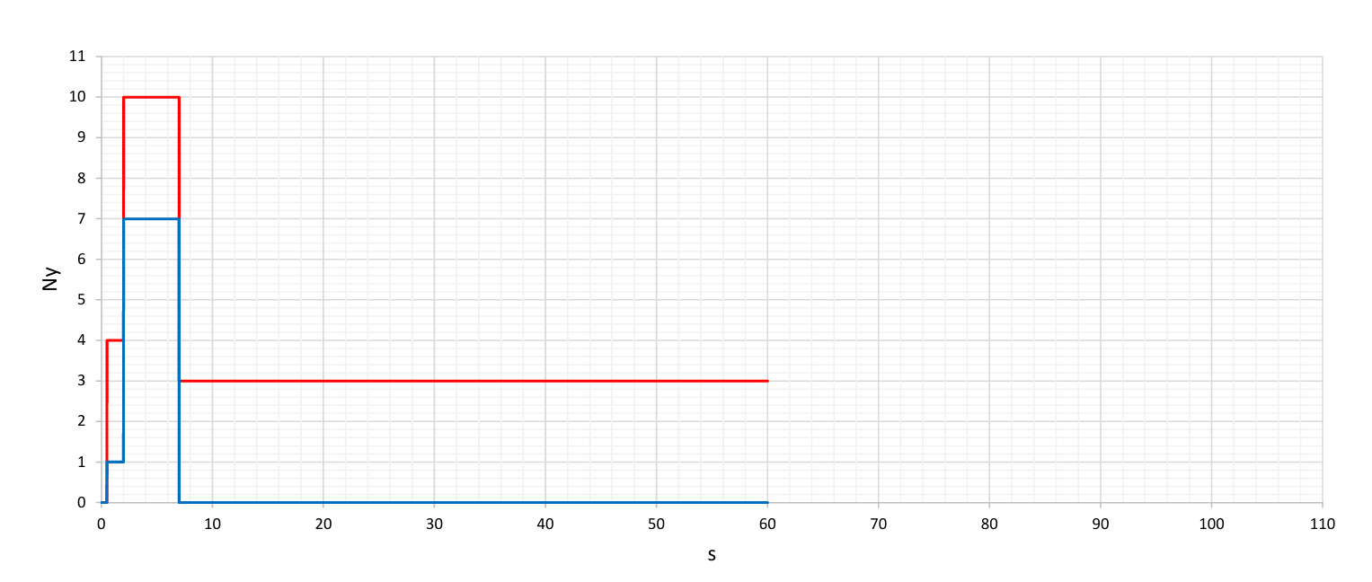
After Russian motors, now again a little bit about American ones. I’ve already worked something about AMRAAM motors and maybe it’s time to complete it and to make it in more decent way From top to bottom WPU-6/B, WPU-16/B and just for scale size comparison RDTT-542U. AMRAAM motors are actually very similar in concept (which I don’t like at all, by the way), propellant weights are known (in previous works I missed it and gave too much for both motors). Information about exact properties of propellants are of course not known but both are from same group of HTBP reduced smoke type. What I did is that I used now exactly same propellant properties for both motors, exact same nozzle geometry and erosion rate of it and just extracted outputs following grain geometry which is slightly different in these two motors. What is kind of strange is that first motor is classified as boost-sustain and second as all boost. While first one indeed has dual thrust curve, although with not so significant pressure (thrust) drop, second one is also with output which is actually not what would be normally called all boost motor. Why they classified it as all boost I don’t know, but it wouldn’t be first case. In what I’m pretty sure, is that geometry of grain as it is must give higher starting values then when motor is finishing its work. I like much more pressure data outputs than forces but people usually are interested in forces only. Although internet write all kind of numbers for these motors and some ridiculous values of specific impulse (probably because it is HTPB and not only that, it is American and recently new HTPB) these outputs of mine I find as quite fair and realistic. It is 12400kgs and 11100kgs of total impulses or average 240s sea level specific impulse which looks fair and square.
-
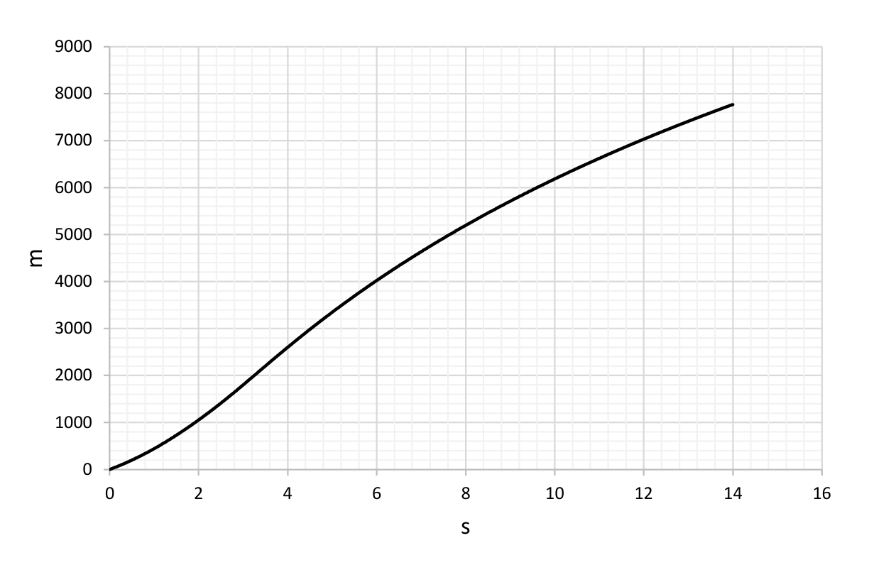
Don't remember did I post R-60 motor rework earlier, same as with R-27ER I was wandering with number of points in star configuration, first with 8 then with 6 but seems it could be awkward number 7 after all. There are lot of photos of this cross cut rocket model on the internet but for this purpose all taken from some stupid angles This is best I found and after some retouchings and after many doubts and questioning, I think 7 should be. If someone has some better photo from personal archive it would be appreciated. In any case 7-point star will give what is in description of this motor, a bit stronger initial thrust -> This is thrust case for +50, +20 and -50degC at sea level and this is 5km situation which is with nearly perfect match to documents ->
-
-
Few more pictures of R-77M appeared
-
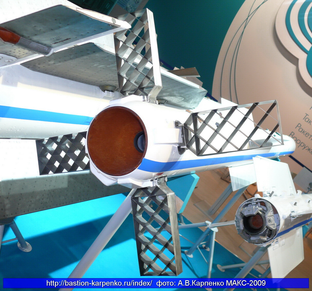
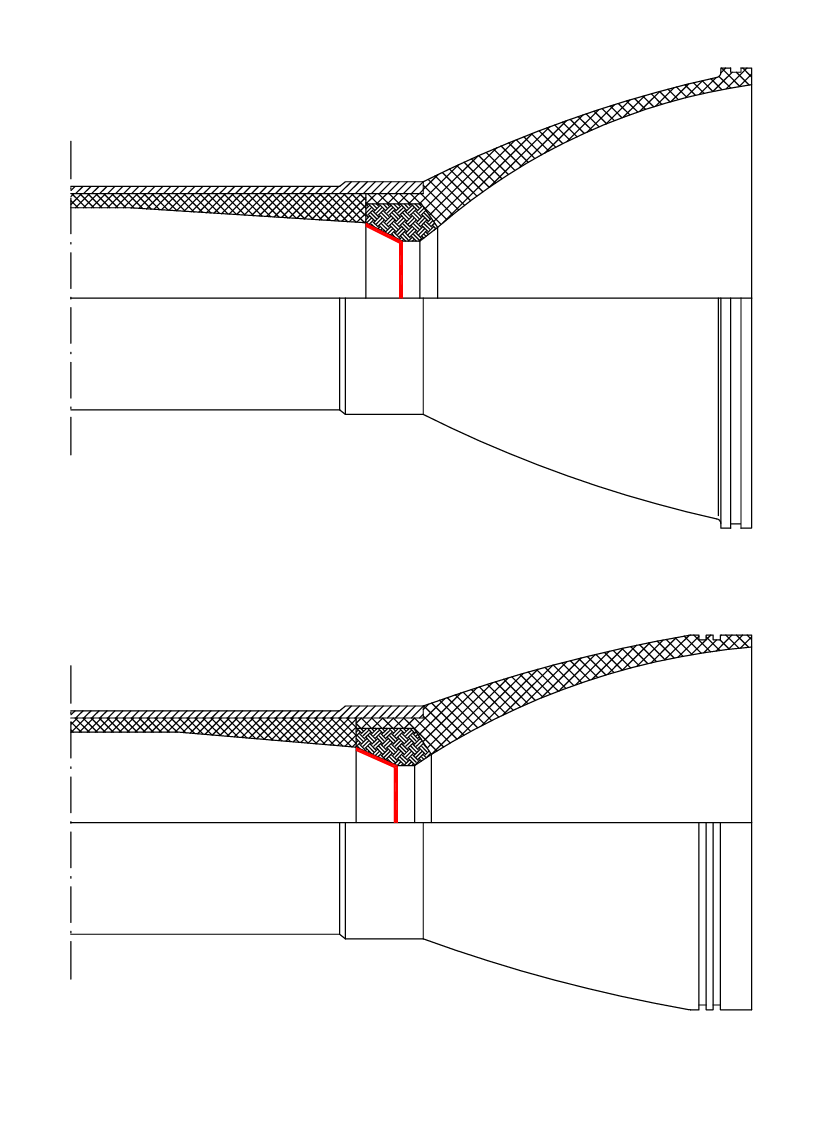
This is the best rear view of R-77-1 that I found, and to be in some normal focus to allow taking measuremets. Seems like throat in R-77-1 could be a bit more tight, diameter of seal (сопловая заглушка) from this photo is something about 50mm Seal can be installed in various ways -> but I think this last one (bottom one) is the most likely how it is fixed in nozzle. That means that throat is more likely 40mm what is kind of less then in R-77, and exit diameter is something like 148mm what makes initial expansion ratio 13,7 and that is in range of R-77. But 40mm throat diameter could result that this motor works differently, propellant must be with lower burning rate, otherwise motor would blow out Slower burning -> longer burning Total impulse is still in range, about 14300 kgs at sea level and 15500 at 10km And this longer burning motor gives very nice push in lofting -> It would be nice if there is some video which can give clue how long motor burns, but I haven't managed to find some
-
Yes, that’s it, always some polynomials which define trajectories to have maximal velocity when rocket reaching target and to be kinematically released when starting to chase target
-
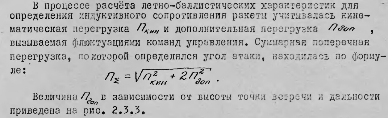
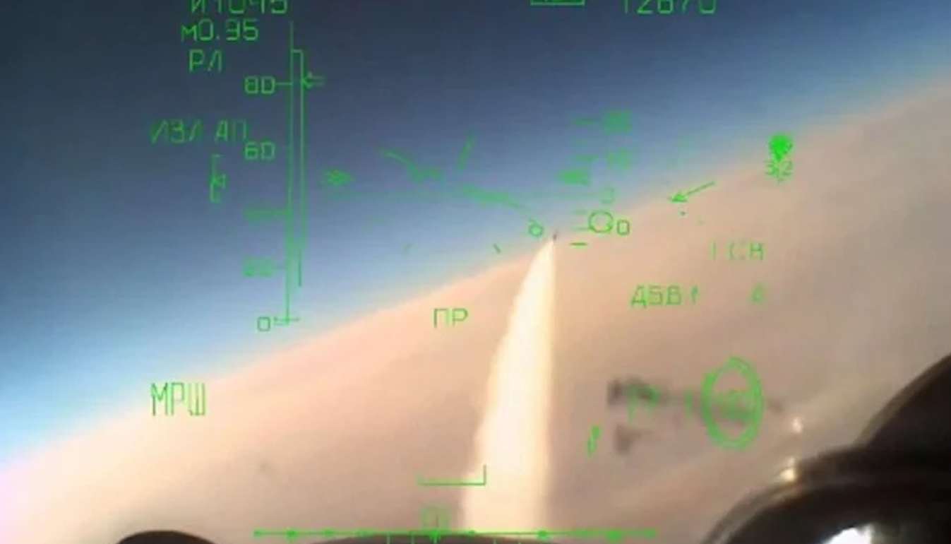
I think I will need to remodel a little bit my programs for trajectories. In all previous cases (mostly focus was on R-27R and R-27ER) I’ve never managed to fully match all envelopes of launching, usually at 10km I was very close to match it, but on higher altitudes I always had a little bit underperformed results. Reason is most likely in incorrect involvement of this overload reserve (запас перегрузки или дополнительное нагружение). I was simply just making sum of kinematic overload, for example 1G for leveled flight, and 3G as reserved overload, making total of 4G, and used same for all altitudes. But most likely it doesn’t work that way, it is not just sum and most likely запас is not same for all altitudes. This is not related to air-to-air rocket but principles could be same or similar. In this case for targeting at altitude 10km calculating overload is 3,1 (total ones) but for 15km 2,7 , 2,2 at 20km etc etc, and that same principle could solve my mismatching.
-
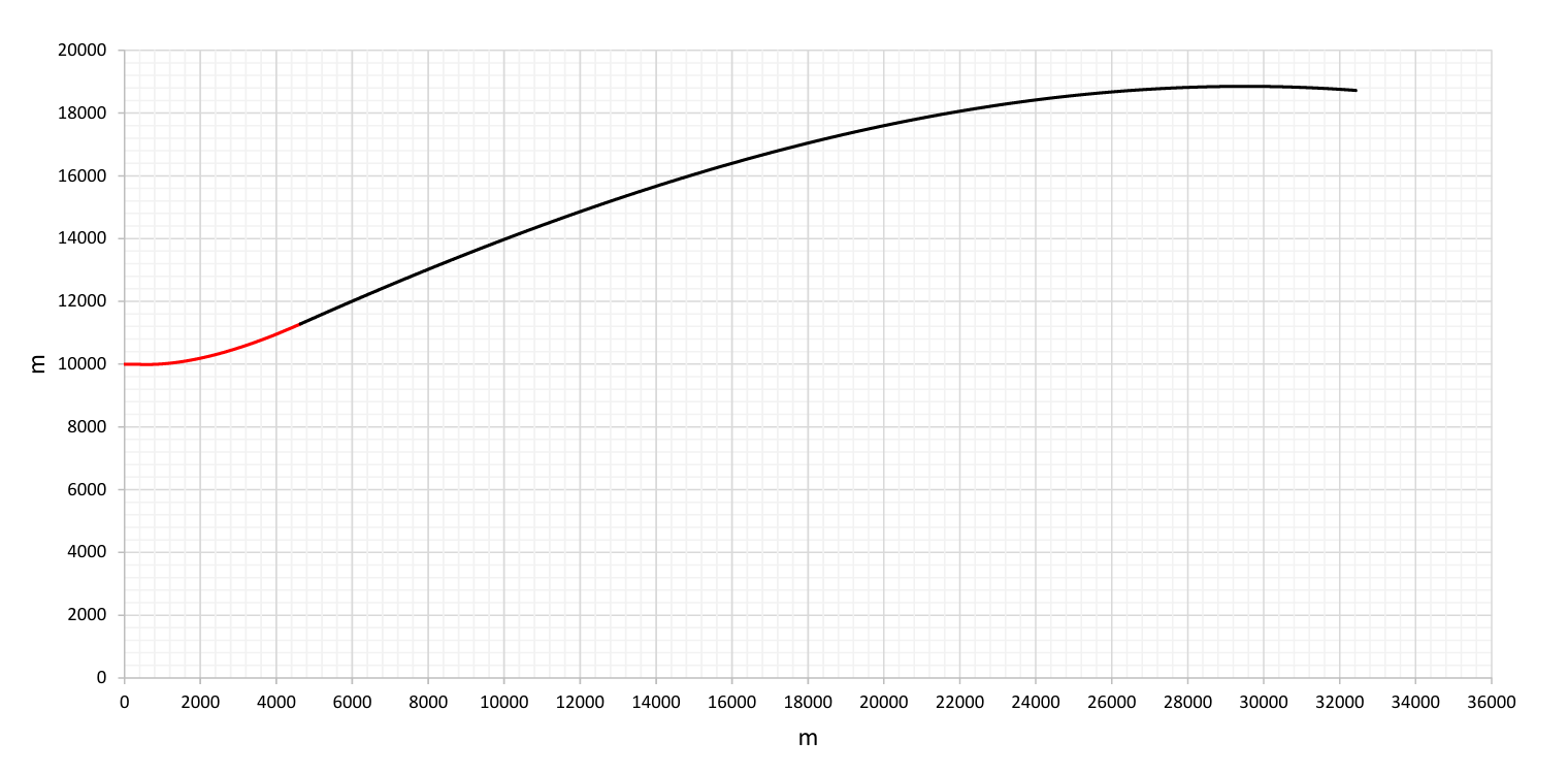
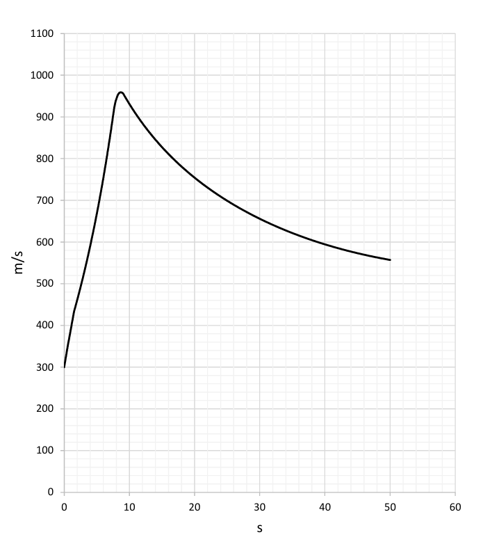
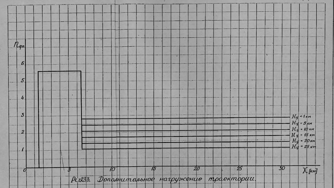
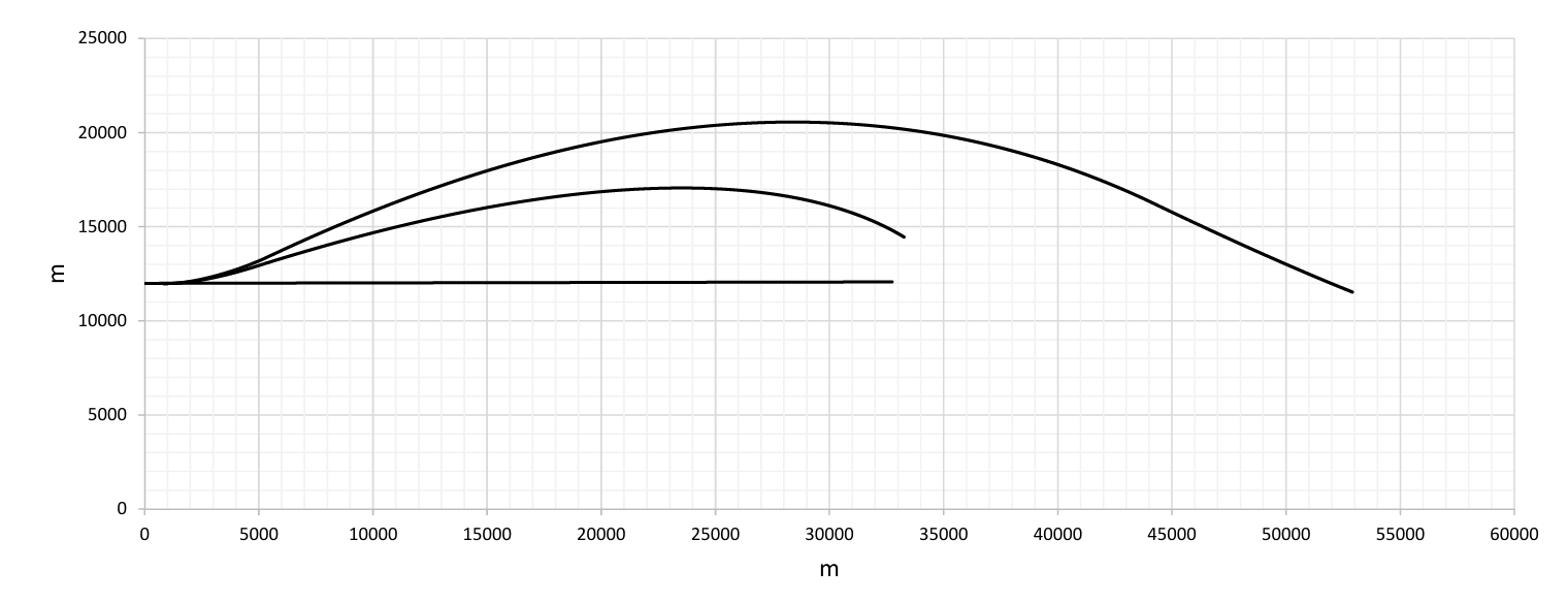
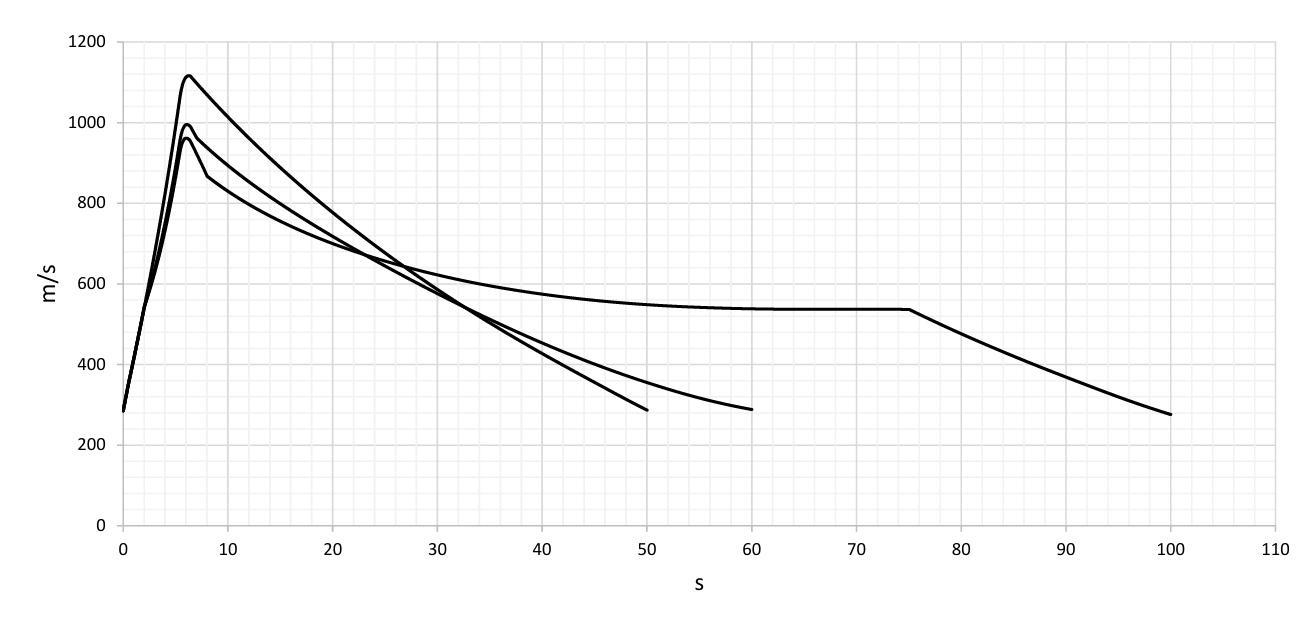
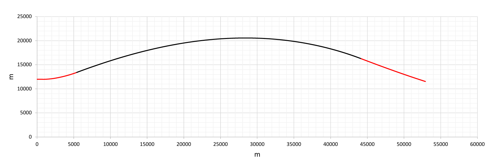
Attempt to reconstruct this case, very low launcing velocity, fair altitude and very high distance to target. If it's true, number in circle present seconds till impact, so 100 seconds which is very long travel. I have no clue where is target on altitude and how fast it is so let's consider it to be same. Several options: 1) levelled flight 1G overload plus 3G reserve 2) initial lofting maneuver and ballistic trajectory but keeping 3G reserve Both of these cases are pointless, not even close to reach target 3) initial lofting maneuver, then ballistic trajectory without any overload and/or reserve and at the end gliding with 1G overload with included 3G reserve Only this thrid case can bring rocket that far and also to have at least some velocity at the end Approximately 67 seconds of passive flying object, with locked fins in zero position, with no lift force whatsoever. I have no clue could it be case, it is completly differnet approach compared to other Russian rockets, I mean on absence of this overload reserve. But only this way I manged to drag rocket that far
-
Yes yes, I understand this was drag with AoA=0 but Cn function will be needed as well to make some external ballistics If you have time push the rocket at sea level 1, 2 and 3M and push it to 15 degrees to see Cn values. These 3 reference points should be enough
-
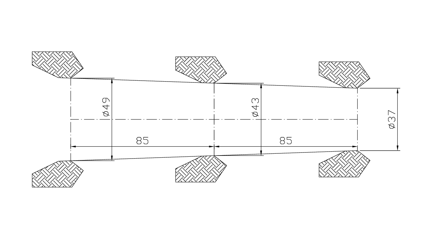
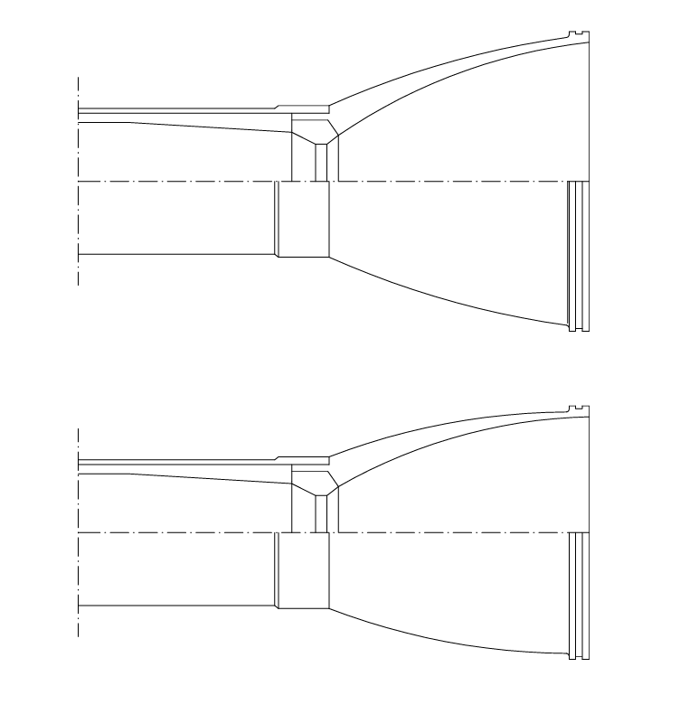
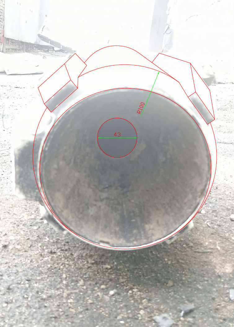
One very questionable method but result that I got is actually what I was expecting it will be Determination of hole's diameter based on two different reference measures and than finding third one which dropped out to be in level of what is in R-77 motor So it could be something like this, R-77 and R-77-1 nozzles, initial area ratios 14 and 10 respectively About propellant grain configuration, I think both motors have same 5-point star grain, here signs of slivers can be seen very nicely
-
This looks nice and fair Lift coefficients will be needed as well, either Cy f(M) or Cn f(alpha), three Mach numbers will be enough (1, 2 and 3M)
-
Anyone has idea (some tools) how to figure out what could be hole's diameter. Picture frame (focus) was not taken very happily and I think diameter is not so small as it looks on first view. R-77-1 of course is on picture. Actually I don't even know nozzle exit diameter so that info would be also appreciated
-
That is good point and question in same time. Do we have actually valid document that give 190kg to 77-1 ? For R-77 sources say 175-177kg and extra 110mm (R-77-1) supposedly made total of 190kg. Now new extra of 300mm made R-77M but this extra 300mm I count only as extra length of motor and that is just propellant and chamber casing what is 15-16kg


.png.44bb602b94dc814cdc0cec24229eabec.png)