

tavarish palkovnik
-
Posts
476 -
Joined
-
Last visited
Content Type
Profiles
Forums
Events
Everything posted by tavarish palkovnik
-
Already in active usage

-
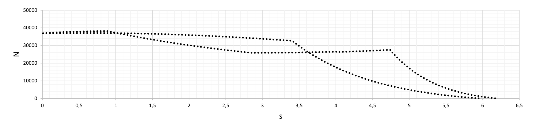
New model from R-77 family starts to fly. Looks something like 300-350mm longer rocket and if I would give dual impulse to any rocket, this one would be that
-
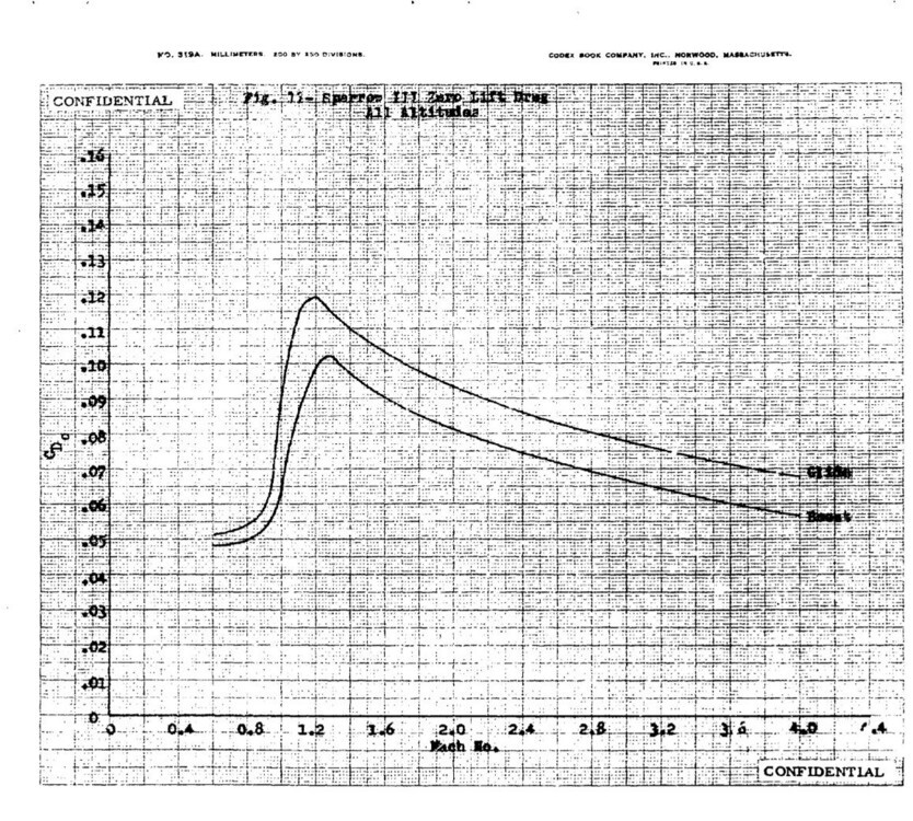
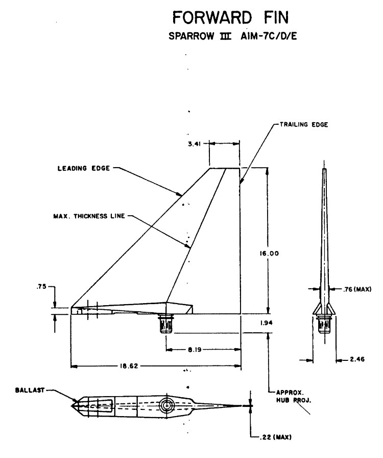
When mentioned Sparrow, I don’t know if already had conversations about this drag function attributed to Sparrow Don’t like this “all altitudes” but never mind, differences are not so dramatic. But this function without reference area is not much useful… In any case, it should be area of two fins making peak as 0,84 counting with body cross section area
-
I was questioning why and how comes there is no yet on internet drag function for R-77. Really it is not easy to calculate such configuration, actually I'm giving up of it. Simply I don't have enough literature to make some reasonable, at least approximative calculation. All other rockets with normal fins can be quite easily calculated and results were not so bad, actually where had valid data to compare, not bad at all. There are several paper works but mostly they have focus on drag of individual fin, and I'm interested in full assembly. I was mentioning base pressure, one of the easiest parts of total drag calculation, but here with grid fins I just stuck and don't know how to proceed. And like said already, I'm expecting this part together with pressure on fins to be significantly higher then what is case with classic fins or wings whatever is in aft zone Few such aft section surfaces, Phoenix, Sidewinder and Sparrow For all these configurations base pressure can be easily calculated, and this ''c'' number (ratio between wing thickness and aerodynamic chord) is for these samples approximately 0,036 ; 0,046 and 0,09. What grid fins make on body base I have no idea ...
-
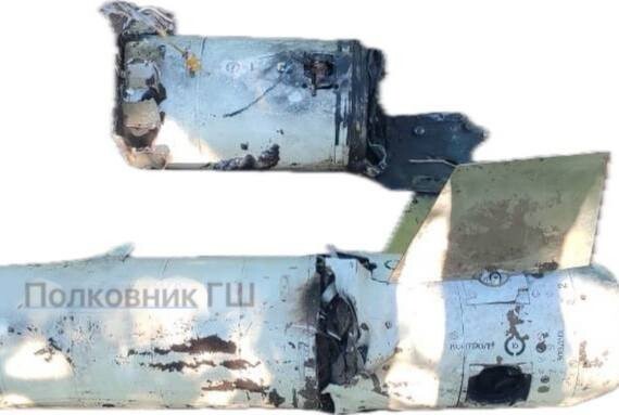
@MA_VMF Don't take me wrong but it would be fair to write few words with applied image, otherwise images become ->
-
New tricks, single image for two different situations ? Bottom is sea level seems like, and top side something higher altitude, and looks like some higher velocity then 0,8 mach number. And I'm very curious to see how this ''blue'' part (vacuuming) will develope with velocities
-
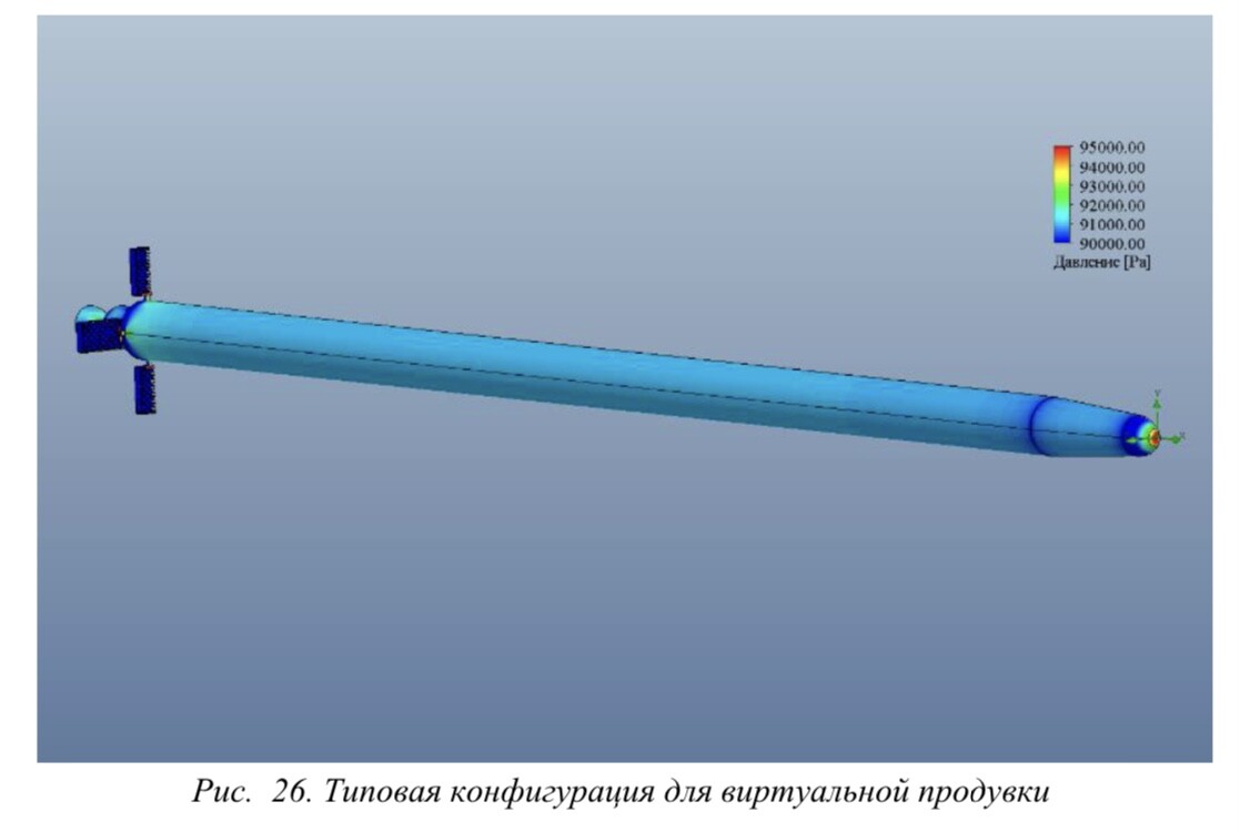
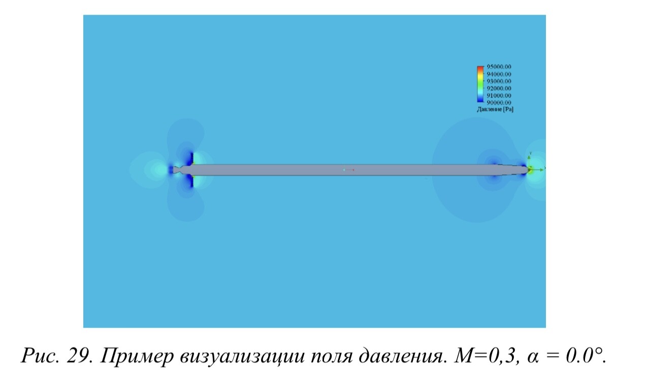
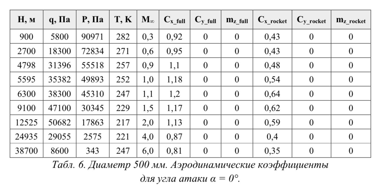
It’s kind of hard to find some texts with given numbers of drag coefficients for full assembly, for rocket with grid fins instead of for fins only. This is from one of such rare paperworks. Configuration is some sticklike wingless rocket with not very aerodynamic nose and they made and gave numbers for three different diameters, 500, 700 and 900mm. Table shows numbers for 500mm configuration where Cx_rocket are drag coefficients for rocket without fins and Cx_full coefficients for rocket with included grid fins. Interestingly, and not surprisingly to me actually, added fins increase drag coefficients making them as much as twice higher in average. In finless configuration only pressure on nose, pressure on base and body friction participate. With adding fins, two more components appear, pressure on fins and fins friction. While second should not be something significant, first could be. But I think the biggest difference could be base pressure. The lowest base pressure will be of course always in finless configuration. Classic fins increase base pressure of course and I think grid fins increase it significantly
-
Not sure which kind of results for comparison will be the most suitable so few more, situation 1,5M and 10km
-
For comparison when numbers from CFD arrive...Cx58 added just for pictorial representation of differences
-
Mach number 0,8 will not help us a lot to figure out what could be final score. Of course it would be great if you can make as much situations as possible but I think the most interesting range, and range where I expect really significant drag, is between 1,1 and 1,8M. I hope you will manage to finish this interesting piece of work, and I'm expecting curve of drag coefficients in form a little bit different then it usually looks like
-
Sea level ; M=1,5 ; AoA=0 perhaps ? Bold prediction if it is sea level and 1,5M and of course if you extracted numbers -> Cx something about 1,25-1,3 Cn 3,7 (AoA=10deg) Cn 11 (AoA=30deg) ... or it is M=1,1 more likely ... 1,75 ; 4,4 ; 14,8 respectively
-
If I say this is with 95-98% precision reconstructed motor, would it be enough? This is after all, just one more motor layout in line which I shared here, beyond others for which you will hardly find something on internet. But everything can be found, one way or other
-
Motor is clear more or less Now I can just wait @MA_VMF to finish Cx and Cy functions to make пуск with more accurate data. Hope it will be done in this lifetime Until waiting, one bold prediction for rocket’s passive Cx at 1,1M AoA=0 … 1,4 with body cross section as reference area. Cy something like 0,6 1/deg
-
I kind of disagree, manual calculations of individual components of total drag and making sum of them can be quite precise. Of course wind tunnels or live firing of telemetric missiles give real and true values, but if you read old documents (when manual work was only method available) differences are not so big, actually in most cases calculations could be accepted as quite accurate. CFD is nice piece of technology, but CFD is nothing more than program where all theoretical principles are combined in one helpful tool. Nose pressure, base pressure, wings pressure, body friction and wings friction and there it is. Some of components like base pressure are with including interface of other elements, wings and boattail configuration and shape, and all that is part of calculations. Actually I think that main reason why missile with grid fins has something higher drag compared to missile with classical fins is not so much because of pressure on fins but because of higher base pressure
-
c=относительная толщина профиля крыла=отношение наибольшей толщины крыла к хорде When fins are in classic form I understand and know how to calculate base pressure drag...but how to calculate it when having grid fins !? What should be used for thickness, thickness of just one layer in grid ?
-
And what larger fin deflection, larger possibility of air stream sliding over fins, larger angle of attack of rocket in general make as result in final dragging
-
Tomorrow I could have some free time for one experimental work. Rocket 9M79 has grid fins and for this rocket I have plenty of inputs for testing. Motor is fully known in all aspects so it’s work with gradual changing of altitude can be very precisely modeled. Trajectory to maximal distance is also known, how many seconds flight takes etc etc Only what is unknown is drag coefficient function to match max distance in exact time. At the moment, because I already made program base, to match it passive i58 should be 1,25 and tomorrow I will calculate what could be i58 for rocket without fins and for rocket with some classically shaped fins in reasonable size. I don’t expect some huge difference but we will see when results drop out
-
Nice view on motor interior (radiography) I had, and still have dilemma, first I was on side of HARM motor, then split it 50:50 between HARM and Sparrow, but after reconsideration, this should be most likely image showing Mk58 motor
-
Couple of new ones, actually one lately just remodeled (513-1) and other (507) started from blank Both motors are with significant sliver stage, one maybe with a bit to long but I don’t see some other reasonable configuration except this 6-points star Although geometrically quite different, total impulse and propellant weight nearly same, under 6% difference For 513-1 I’m quite sure now it is with 8-points star, for 507 not fully sure in this 6, so if someone has some helpful graphics it would be appreciated
-
??
-
@MA_VMF Will you give some words about these results. Grid fin obviously and you showed us dynamic pressure values. But this pressure is actually the easiest part of these calculations, simply density * velocity^2 * 1/2 … 1,225*680^2*1/2=283220 Pa To me and for most others I guess, all these CFD modelings are “gold” digging where “gold” are Cx and Cy coefficients in function of Mach. When having these coefficients everything else is just piece of cake. So how you find those coefficients? I guess software gives you drag force and from that Cx coefficients just drop out. So why and what for dynamic pressure? Just from curiosity, how long it takes, with some reasonable calculation grid, to get drag forces on let’s say 10 different Mach numbers at same altitude? Hours or days? Generally, what takes the most time, making 3D model, or defining initial conditions or simply time computer needs to process data? By the way, R-33, is it finished I really don’t have clue how long it could take for one rocket to get ballistic data from software. Yesterday, boring Sunday afternoon, I processed on rocket and let’s say in two and half hours I got Cx, Cy and roughly moment situations to define static stabilities of rocket depending of altitude, velocity and angle of attack Maybe I’m just wrong and taking all that very simplified, but I question myself, why internet is not already filled with mostly all, if not all, rockets processed Of course others are also welcome to share thoughts
-
Content is not visible Hit it one more time, and with note what it presents
-
Fully agree ! Beside that...final drag coefficient, from angle of attack induced one, goes in drag force
-
Look nice and fair This is what I use for R-33, just common i58=1,35 rule Your function in area where differ the most is about i58 1,45 so just as sample what it makes in flight, 1,35 vs 1,45
-
R-27R sea level ?
.png.d6a7cbb29db434baed593415e9aad5b1.png)
.png.04c62fd69572c96365f7d3453c58f9ce.png)
.png.6db529c73f895c5e9d0cff279385ea1f.png)
.png.15c92fc2522bf859ffbf18d5a4364328.png)

.png.10a84f6b8914fc8bbafcf62d938d7cbd.png)
.png.7dac9da64395c8b59547e24599dcfe69.png)
.png.7ee45ca83ec6b0249580c9ce0538d53a.png)
.png.4c7a3ba7ef99b56b07672ecbecd83603.png)

.png.278706a31f7eddc5e753bc9890719642.png)
.png.c5c985d80206292aa87bd305e6d6b0a2.png)
.png.501d5718154f16cb80d5a419deee5a27.png)
.png.d3d1463a146f6375647278cf300031b8.png)