tavarish palkovnik
-
Posts
476 -
Joined
-
Last visited
Content Type
Profiles
Forums
Events
Everything posted by tavarish palkovnik
-
@Naquaii Appreciated for came by and shared your points. It’s pity to hear not to expect your participation in discussion that much, it is kind of hard that way to have normal exchange of thoughts and in this case arguments. Saying, you have your source trusting more. And I guess 13595 N for 27 seconds is from that source which is not for sharing. To be clear, I’m not asking from you to disclose it, if it exists after all, here we already disclosed so many sources that motor actually and literally “drew” itself Having no intention to participate in sharing arguments, and keeping your side on the trust base, is accepted although disappointed in same time. Honestly I was expected more from you guys work ( and sell ! ) this products, more than just “we trust more” in opinion A than opinion B or C without even trying to disprove others. All right, then I will disprove 13595 N and 27s the only way I know, by mathematics. Indisputable method always and every time. So let’s see shortly what is behind these numbers above. If we have nozzle data (hopefully nobody will doubt in CPIA data) and if we put it in thrust formula we got equation with two unknowns, pressure and thrust coefficient. Hard but not impossible to solve, with making iteration matrix we come to chamber pressure of 41,6 bar to make 13595N through this nozzle. Now when having chamber pressure we can come to burning rate (hopefully nobody will doubt in W.T.Brooks data, this engineer literally “had hands” in this motor. So 6,22mm/s is burning rate in your motor. To have constant chamber pressure 41,6bar (600psi) burning surface of that grain must be constantly 0,6 square meters. Having burning surface, burning rate and expected propellant density we get mass flow in your motor as 6,531 kilograms per second. Your motor blows 27 seconds so it means your motor is looking for 176,3 kilograms of fuel…oops…isn’t it 163kg in your motor!? Let’s continue with 176,3 because that much must be to have selected thrust output since nobody disapprove nozzle geometry, who would dare disapprove NASA and CPIA. And at the end we get specific impulse 212s what is exactly something as expected to be with 18,5 nozzle expansion ratio, at sea level and with chamber pressure 600psi. I know you guys from terrace will find some explanations in form that I don’t know what all and what exactly is in their codes etc etc … come on … like it or not … but you have fake product

-
I do believe all that was done with good intentions, but from some reason something happened, either accidental error in calculation of theirs, wrong reading of sources or just simply not understanding of principles. And Frankenstein of motor (motors in their case) appeared and flooded internet. Reverse engineering of motors with significant lack of inputs is not easy, luckily here we managed to collect so many so valuable stuffs that final touch was not problematic. It took lot of time, lot of from today’s perspective wasted attempts to figure it out what is inside, but at the end everything just settled on their place. Russian motors of air-to-air missiles are so much easier to understand and to make reverse engineering, literally there are only three propellant grain configurations used, internally/externally burning cylinder, internally burning star and classic finocyl…and Americans oppositely had/have variety of sometimes abstractive shapes and geometrical acrobatics from who knows what reason Administration…this is my graphic, so please don’t add extra warning points or ban actions Anyway, Americans practiced so many various shapes resulting with various motor’s outputs and even here in these radial crosscuts Phoenix just pokes eyes in extra. Simply this motor is unique in several characteristics so it’s not surprising if mistakes happens when trying to understand it
-
@Katsu Russian reverse engineering delusion they said Where it was, why you didn’t call me to participate in that nice conversation Internet is such a great thing, so many valuable things you can find and learn on it (in my time I had to go in library and wait my time to get a books when return from others), but like in wrongly “used” democracy where everyone has rights to “open mouth” , also so many rubbish, unfortunately rubbish long time ago overtook it. I like your point, the one when having no solid answers in written form, to find it using same principles used by developers of that thing of interest, in this case rocket motor. Although rocket motors are not simple to understand, still everything inside of it are just simple physical processes…fun fact…those are same on east and on west Indeed I use some formulas described by one Russian scientist long time ago, before these guys called that as delusion, most probably haven’t been born. I was reading recently Warthunder forum, mostly same discussion about Phoenix and motor particularly because motors are of highest interest of mine. There were some good things to read there…unfortunately I was not able to write there because that forum is just for those playing that game …but also so many…hmmm…how to say and to be polite. Few weeks it’s silence there, and they have been so close to figure it out. Of course, over there is like you described, discussion between developers “fan club” and those who questioning One guy was so close, it was topic for who knows how many times started and never ended, specific impulse of motor…and on literally next page from literature he shared everything is crystal clear, how specific impulse is changing with altitude, pressures and nozzle expansion ratio…but fan club concluded…it is same old motor like early Mk36 of Sidewinder and old motors are…just old and having low specific impulse of something about 230s or 240s…OMG Fun fact again…even propellant in historically old HVAR rocket had 235s impulse, but propellant useless for wide temperature range. What I want to say…actually I will not…it can’t be said shortly and there are so many variables. Phoenix…why it’s vanished…because war theater (threat) is changed. One of primary tasks of Phoenix was fighting fast flying high altitude targets no other missile can reach (Phoenix was designed that way to have such possibilities…nozzle expansion ratio etc etc) but low flying cruise missiles also appeared, local conflicts with targets of different kinds…Phoenix became unnecessary assets…of course traditional American sense of business made its job as well So, no matter of anything, Phoenix deserves truth. This motor although I’m not huge fan of American principles of building rocket motors is actually really nice piece of work
-
Nice to see discussion didn’t “die” and fight for truth is continuing Katsu, I don’t agree with this 5 Mach nonsense statement, actually I see 5 Mach as reality for missile’s top speed in launching conditions at maximal limits, maximal altitude and maximal velocity when launched (58kft and with 2M) And you are right for this about high flying situations and low air density. Let’s make one test, up there, to see how much drag coefficient influences over there. Let’s make Phoenix to be in shape of wood log… Drag coefficient of such cylinder shape nose is the worst one, let’s take it as continuous 1,6 from 2M to higher. I will not include body friction and also will not add some wings on this wood log, this nose of log will be enough, worse than this can’t be of course. So, let’s see how Phoenix in such shape with continuous drag coefficient of 1,6 would fly if launched ballistically with 20 deg elevation from 58000ft at 2M And in two thrust configurations, the one I’m giving to it and other what you have in game So let’s see what speed wood log would reach… Hmmm, 5 Mach is not so far away, even wood log up there if have good push from bottom reaches respectable speed Fiction of course, neither Phoenix is wood log neither pilot attempting such suicidal launch at upper maximal limits is fool, but normal Phoenix launched from this launching point, horizontally, with missile’s overload to grab even thinner atmosphere will reach 5 Mach for sure
-
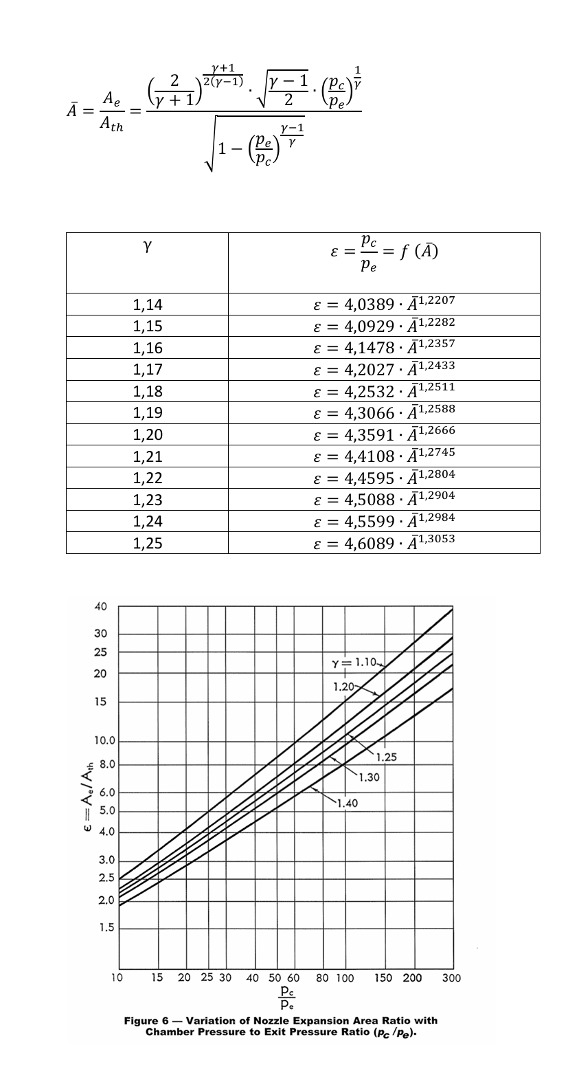
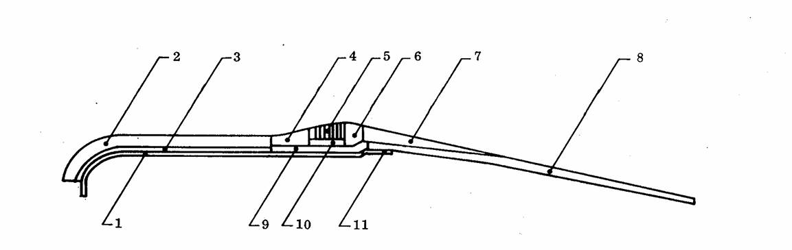
It’s only important that we understand each other, dot or coma it doesn’t matter…you didn’t see when I do hand written calculations that sometimes even myself can’t decode a day after But let’s go in further demystification of Phoenix, now through geometrical features. You saw how much important nozzle configuration is to motor output, change it and results are totally different. But let’s that be second point. First, just shortly one more time about burn time. Because of various factors, facts and necessities, propellant grain is “showing” that burning web is something like 6” (152mm). We have facts from Rocketdyne that burning rate of that propellant at 1000 psi (69 bar) was 0,3” (7,62mm) and at 700 psi (48 bar) 0,255” (6,477mm). Enough to define burning rate law as 1,4*p^0,4 to be close enough. I’ve got average pressure 45 bar so burning speed is 6,42mm/s and at 20degC web of 152mm will burn for 23,7 seconds. At -40degC burning will be slower because of minus what will also consequently decrease pressure so total final burning speed will be smaller because of combining influences and will be 0,8734*1,4*36^0,4=5,13mm/s At +70degC same story only now average pressure rises to 53 bar and results with 1,1055*1,4*53^0,4=7,58mm/s So limes numbers are 152/5,13 and 152/7,58 or 29,6 and 20 seconds respectively, max and min burn time. OK, this was not just geometrical features but numbers again, sorry. Second point, I think I didn’t write about it here on this forum. Strictly geometrically to show that Mk47 and Mk60 should not be much different in output, if at all, and I believe not at all. NASA in their handbook about nozzles gave two graphics, first one undersigned as Phoenix nozzle and second one explaining pyrolytic graphite throat inserts Obviously from external geometric features first one fits to Mk47 and second is very sure of Mk60, especially because in same handbook given parameters are of Mk60. Graphics are not exactly in scaled proportions but we already have enough geometrical values of Mk47 When having all this, and when set some of dimensions as referenced, it is easy to draw it in scale enough precisely From top to down, external view of Mk47 nozzle, Mk60 nozzle overwritten on it, Mk47 interior over it…and combined! Turn it upside down, twist it all around, but conclusion is just there
-
1,013 bar = 1013 mbar = 101300 Pa = 14,7 psi ... I think you something mixed up
-
A bit more mathematics and numbers in one fiction... What if...everything inside of motor remain same, same configuration, same throat diameter, same propellant, same heat ratio etc...of course burning process would remain same with same average chamber pressure of 45 bar and average burn time of 23,7 seconds. But nozzle is cut off so that nozzle area ratio is different. I made fiction in way that nozzle should be optimized to sea level altitude, to make full expansion there, meaning pressure at nozzle exit to be equal to atmospheric pressure of 1,013 bar. And that is the one below, now with expansion ratio only 6,455 or exit diameter 140,68mm. For such nozzle thrust coefficients are different of course and now it is 1,68 in vacuum condition and 1,5347 at sea level, so average thrust at sea level would be 0,987*1,5347*4,5*55,372˄2*PI/4=16406 N or total impulse 388822 Ns or average specific impulse 236s. And that is minimal thrust, with every kilometre of altitude thrust gain will be achieved...but not even close as with nozzle with expansion ratio 18,5 At 25km it reaches 17940 N what is 9,35% gain or for all 25km differential average 6,7% tanananana Also it is interesting to see situation with Isp which is now between 236 and 258 s Joy of numbers, I just hope nobody will take these numbers anyhow related to Phoenix, this is just a fiction in way ''what if''
-
Thanks anyway! Yes, seems there is no online info what would be values of these two thrusts in dual thrust configuration (or configurations) There are few sectional views of motors (cross sections), mostly longitudinal, sometimes with radial sections also, there are also some info about propellants…but everything is so messed. The most relevant longitudinal cross section which is certainly dual thrust concept, unfortunately is without radial section cuts and beside that, signed as motor which is based on several sources…single thrust motor
-
Do you have this specifications for Mk 78, I can't find it in some readable format. It would be appreciated if possible to share it here. Of what I've found about all these Shrike's motors, I only got total confusion. Mk 78 Mod.0 Mk53 Mod.4 and Mk39 Mod.7 are what I'm interested for. For first two there are some sectional views (which are kind of same actually based on source) while Mk39 Mod.7 is total mess. Some says it is single thrust model while other says dual thrust, and two totally different concepts (sectional view pictures) are signed same
-
Already have employment, this is just a hobby and interest of mine. There is no enough math, never been, math is all around us. Tell me please, what do you think, do you have in this simulation correctly modeled Phoenix in mechanical point of view? This second sentence of yours is very worrying. Looks like situations in corrupted states where if you are not member of ruling political party you can bark all days long and nothing will change Just joking, now honestly, like said it doesn’t bother me at all if anything get changed or not. But if I manage to make, at least few to get interested in all this and to start asking questions and perhaps express doubts, the goal is done. Once I said here, flood on internet of wrong information about Phoenix is coming mostly from DCS and WT. And I stand by that, simply, I don’t know terminology for that, but googling commonly sends you to related pages and then it is to late So, math will continue , maybe guys from HB, or HB is a guy, I don’t know, will join us in this conversation, who knows. Stay well all of you
-
Keep trying, there is somewhere in these last pages PS: short input, short output
-
Already done at -40degC but seems you didn’t read it Fun fact…fuel in wings of passengers airplanes…outside hard minus, but friction which rises with altitude in same time warm that same fuel and fuel is in normal liquid state and there’s no need for heating elements Of course when aircraft goes in supersonics that change everything but not in way that minus will overcome but aircraft is going to be overheated
-
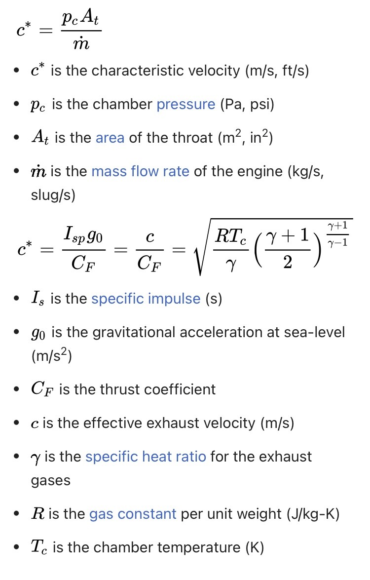
Let’s put this stability aside for now, that would be really too much, of course if someone is interested in this also, no problem whatsoever to go through it. Subject is indeed interesting, not so easy to follow for those not having basics of mechanics but everything can be learned. I said it’s maybe time to leave all this…but no, I will not leave it yet. Few days ago I saw, some guys on WT forum where they also talk about Phoenix, found some document and, step by step, some ideas started to rise, and it is a matter of time when that will flood internet again over already flooded internet when Phoenix is topic. Anyway…OMG how young’s like to say, somehow (I don’t know how) they got to theory that rocket motor burn time depends of altitude and that Phoenix’s motor depending of that can burn even up to 40 seconds … and that’s not all, at lower altitudes when paper work is read literally motor burns 15 seconds Let’s make retrospective and let’s see what mathematics says what is burn time, although it is already clear, at least to me, not from my calculations but NASA’s data, I’ve just calculated it my way to see does it fit, and it fits perfectly, from 20 to 30 seconds depending on temperature. Now let’s use formulas involving neither specific impulse neither coefficient of thrust, but let’s go over characteristic velocity c* What we have fixed: Tc=5400-5700F … average 5550F what is 3339K At=0,002408m^2 (Dtr=2,18”) m=168kg pc=700psi=4,8MPa (Rocketdyne’s data for reference chamber pressure) k=1,2 … like most of Flexdyne CTPB compositions as well as R=307,9 And what would be characteristic velocity from Tc, R and k -> 1563 m/s Now from characteristics velocity, chamber pressure and throat area mass flow rate goes -> 7,395 kg/s And of course end is 168/7,395=22,7 seconds as total burn time, average at normal temperature. With mine 4,5 MPa as normal average it goes 24,2 seconds. 22,5 23,5 or 24,5 it doesn’t matter…but fifteeeeeeen to foooorthy
-
What about Cy function (lifting coefficient and static stability) ? Did he make it as well? You know, with these loft scenarios Cx is not going alone without Cy. And….uffff…this so complex, writing in not native language is difficult especially when subject is not so basic. Shortly, their AIM-54 could easily in this scenario become “AIM-180” , how I from jokes use to say, when angle of attack just turns nose of missile backwards
-
Come on man, don’t exaggerate it now. Let’s stay on ground, this is after all just mathematics and mechanics
-
In these 7 seconds missile is overloaded of course. Overload is α*Cy*v˄2*ρ*A/(2*m*g) and because motor doesn't have enough kilograms of thrust, starting velocity gain is lower. Lower velocity for same G overload means higher angle of attack and then induced drag is coming in game Cx ind = Cx (α=0) + α˄2*Cy/57,3 Everything is connected. Simply, motor as in game and in addition for high altitudes where atmosphere is rare will give such velocity ''brake'' ... which is not normal. Normal motors, by the way, usually have higher thrust in start, just take a look how thrust-to-time curve of Sidewinder looks like. Also one of steps in chain of arming missile in flight is data from motor, data about chamber pressure, usually data is when pressure get down to some fixed value
-
Reconstruction of DCS model trying this 48kft 2M launch Document1.pdf And soon I will again be without possibility to upload files because reaching given maximum
-
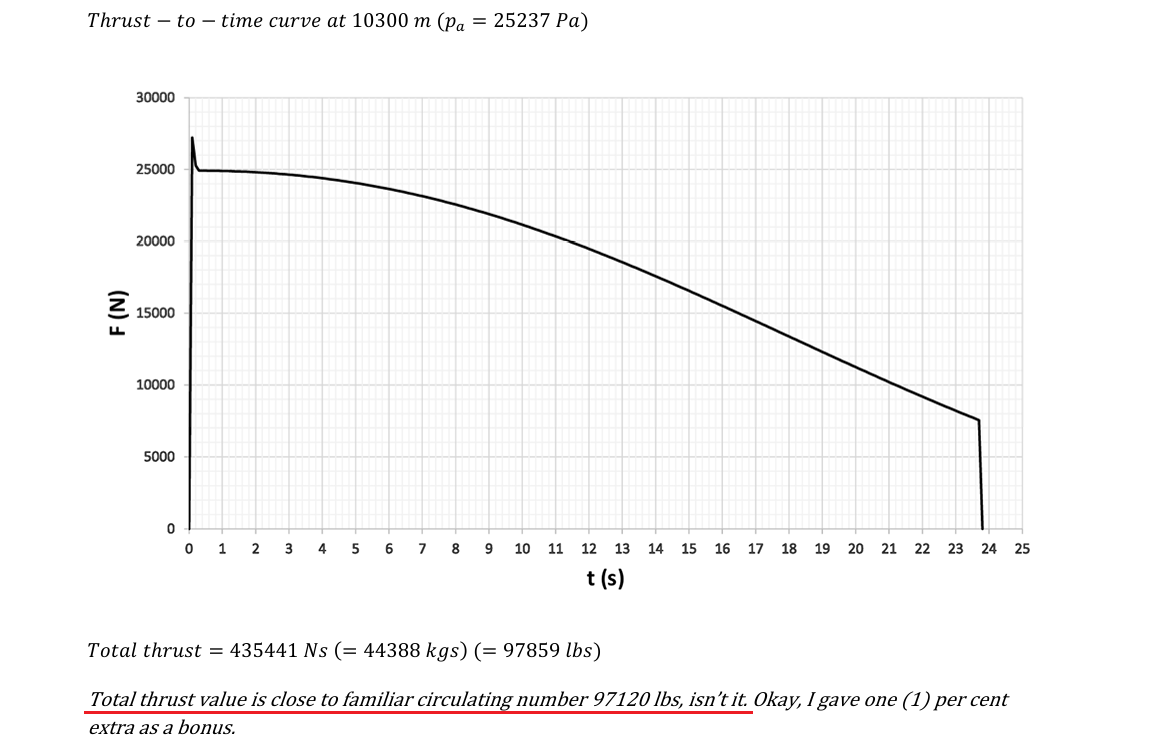
So, in this last image ''red'' case is Phoenix with its nozzle expansion ratio measuring 18,5 and ''blue'' dots are various tactical motors, there are various Sparrows, Sidewinders, Falcons, than Amraam, Genie, pallet of Rs, 23, 60, 27, 27ER, 33 also some air-to-ground like Harm, Hellfire etc. Maverick is missing because its motor is also extreme with expansion ratio measuring just 2, extreme but on other side from Phoenix, so much extreme that third method is not even applicable. But what image is showing? It's showing that all these motors are more or less grouped together, alright R-60 and Hellfire pop out a bit but still everything is under control and understandable why. And all these motors work just fine down, and also up with some slight gain getting with altitude. Only Phoenix is with huge difference in thrust at sea level and up there. That's why it is special case, it is intentionally designed to give maximum where tacticians placed it. Other motors are not so much customized but made as universal, fine at sea level, better when higher but that all is measured in just few percentages...except with dual thrust motors (R-33, AIM-7F, AIM-120B and AGM-88) where this percentage is rising significantly when motor works in sustain stage. I got impression that when common internet write about this altitude gain only external diameter of nozzle is in focus. And that is wrong, without nozzle expansion ratio and chamber pressure all that story is useless. AIR-2 Genie has huge nozzle exit, 296mm is exit diameter what is bigger then Phoenix's bell of 238mm but expansion ratio is just 6,7 and gain with altitude no matter of huge exit area is just slight, nominal sea level thrust of 155kN will be improved just for few percent Maybe is time now to left this, it is up to you guys now to fight for it, to get Phoenix in game in more realistic shape. It will ask for different approach but special case looks for special approach. If I can help with something else just shoot
-
To help a little bit more, to understand how this motor is special and why it should be taken as uniqe case Three methods how to calculate pressure at nozzle exit. First formula is the most precise but very inconvenient to use and it gives pressure 25237 Pa. Second method is approximate method but still fine and enough precise and it gives 25634 Pa. Thrid one is for those not like formulas, and it gives 26163 Pa. All three results are with average chamber pressure 45 bar and heat ratio 1,2 About this last image latter today...
-
Don't be so sure Indeed I can't see what exact code is implemented but with reversible method it can be easily figured out. Maybe you expect that motors in DCS are modeled in details, but they are not and like said it is understandable, who would make all these motors to be precise and perfect. So everything can be detected because of simplifications used in DCS and all other similar games. Give me several level (horizontal) flight envelopes velocity-time and distance-time for active time (when motor burns) let's say 1,2M launch velocity (or better 1M because 1,2M at 1km exceed limits) at 1, 5, 10 and 15km and let's see can we see or not what is code, what is motor thrust at these altitudes. DCS simplified principles is Isp*m, always linear thrust, not involving details like chamber pressure, pressure at nozzle exit, nozzle expansion ratios, throat diameters etc etc etc and that's perfectly right for most of motors. Even 7% principle when increasing thrust as altitude gain is fair enough because it fits quite fine for most of motors...but not this one. Deliberately said ''one'' not ''ones'' and who was reading me know what it means. This motor simply can't be ''molded'' together with Sidewinder, Amraam, Sparrow and pallets of various other tactical motors because with its huge nozzle expansion ratio it is simply different and needs different approach...believe it or not We have saying to someone when ruin established facts, you are destroying snowman, and I know that is exactly what I'm doing But not from wickedness but from engineering needs for precision
- 1623 replies
-
- 12
-

-
You are welcome @Маэстро Of course if something new appears, somewhere, about this motor, to confirm or correct this a bit or…rebut it, I will share it. But like you said, it looks quite reasonable and I fully agree. It is backed with quite enough valid inputs so output should not be much different than this, perhaps just in some finesses
-
It is not academic to quote yourself but what the hech, it is really on the table AIM-54 altitude.pdf
-
You are very right @Gareth Barry with this equation and while with some other motors having small nozzles that simply can be ignored, here with all specificities this can’t be excluded. However these numbers (plus or minus, increase or decrease of thrust force) are not going to come without involving pressures in calculations and your model as much as I know doesn’t include pressure rates when describing some motor. Actually understandable from one perspective and from other, why not to include it if it is on the table. I’m not much about computer-ing but this for sure would be very easy to include. From chamber pressure and nozzle expansion ratio to find what is pressure at nozzle exit. That will be pressure in range of ambient pressure at some 10km so I would put thrust on this altitude as nominal one. That thrust would be so called thrust with full expansion, no loss and no gain of ambient conditions. And from that point this nominal thrust would be changed with (pe-pa)*A where only “pa” is variable and that is piece of cake to make. Ambient pressures are well known and altitude of missile in every second is of course known. There are no linearity here with Phoenix motor so percentages are not precise enough, some other motors can handle percentages easily but here to have as closest to reality, something more have to be done. Average chamber pressure let’s say 45 bar -> nozzle expansion ratio 18,5 -> heat ratio 1,2 -> pressure at nozzle exit 0,256 bar Let’s say it is close to 10km ambient pressure of 0,26491 bar or 26491 Pa, so nominal thrust to be that one or 18318 N. What would be at 2km where ambient pressure is 79497 Pa … 18318+(26491-79497)*0,238^2*PI/4=15961 N
-
You are welcome, actually it’s so nice seeing someone’s interest in this for me such a fun field of technic. As an engineer working for decades, something what is not boring but I’m kind of saturated with that, and bang, several years ago, also on forum (one other, not this one) , my interest in rocket motors was born. Luckily there was a man who worked all his life with rocket motors, willing to share all he knows, with patience at the beginning…and step by step, book by book, my interest just grew, some knowledge is accumulated of course but because this is indeed specific field of technic and just hobby to me, there are still so many things to learn. There were some good points I believe, there were some completely missed ones which I will always admit, either figured out alone with time or pointed by others * So, interesting hobby made boring living work easier That’s why it’s nice to see someone’s interest, and @Katsu what ever you wish to hear about, if available time and my knowledge allow will be done. Unless forum sheriffs don’t erase and expel us * - this freak of motor is I’m very sure well pointed
-
But @Katsu don’t change propellant mass, it is always 168kg no matter what thrust is. Altitude change specify impulse and specific impulse multiplied with propellant mass gives thrust


.png.d85e6a8741dae0b7eaccb2c5f1609d70.png)
.png.24ed4f117e7adf09ee4298e2e8815c3d.png)
.png.2cfba7c409faf9d773f93f38345028fa.png)
.png.ed6f1321cb27fe621501f4935375fe97.png)


.png.2ff3e680453a7a9528726d118b63cf52.png)
.png.75bdc17e5f06ce3e3b076f1b658d1969.png)
.png.0222803f12c610ce885cd43c2d4a3857.png)