tavarish palkovnik
-
Posts
476 -
Joined
-
Last visited
Content Type
Profiles
Forums
Events
Everything posted by tavarish palkovnik
-
You just point the problem... Even for simple configurations, like this 8-point star grain, we are talking about dozens of step points to get at lease decent output and I'm actually more about hundreds of steps how much complicated configurations looking for. So it is out of question making one hundred configurations again and again but one model configuration and offsets. In most cases it will happen that in output in some point curve will ''blink'' meaning something is not perfect so in that case it is time to go back in model, to make slight adjustment, and check it again

-
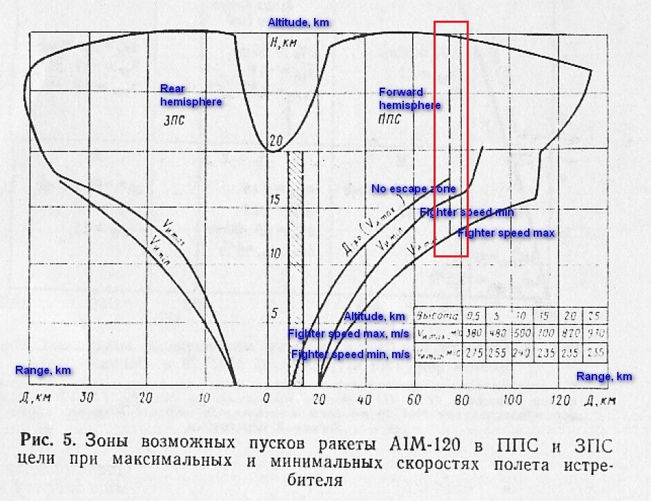
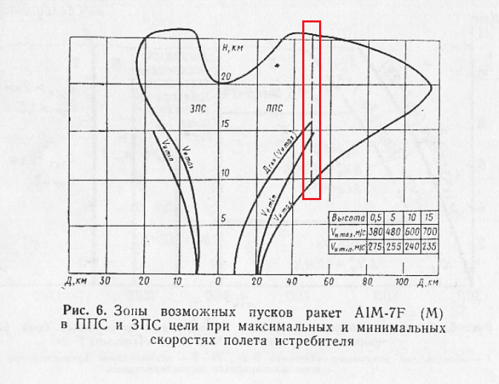
Close but not exactly This is what would be great, to have 3D model, to define surface (or surfaces) which are in burning process and then to make offset of those surfaces. So it is not trim, it is kind of opposite of extruding. Even this simple finocyl form is not so complicated because surface area can be calculated quite precise to make function, but some other grain forms are difficult and when you put in addition various radiuses on edges, when make central hole with slight cone angle as it is always in practise, on slots also etc etc, then it becomes tricky. Just take a look how complicated transition form between slots and central hole looks like on R-27ER grain or on grain of AIM-7F motor Mk-65 and imagine to calculate it or to measure surface area with 2D tools
-
If someone would like to try, one similar cute little motor, 9M116 Metis rocket Propellant is of same grade, motor has three nozzles each with throat diameter 3,1mm. And Internet gives wrong numbers about thrust for this motor Question for all you 3D magicians…how these programs actually work, or more specifically, when you have 3D model I know you can make any 2D projection, but does program allow offset of 3D surface or you need every time to draw new 3D model? In 2D AutoCad when some contour is drawn, offset is so simple, select value of offset and point offset vector and offsets just goes out. I heard very contradictory explanations from 3D program users
-
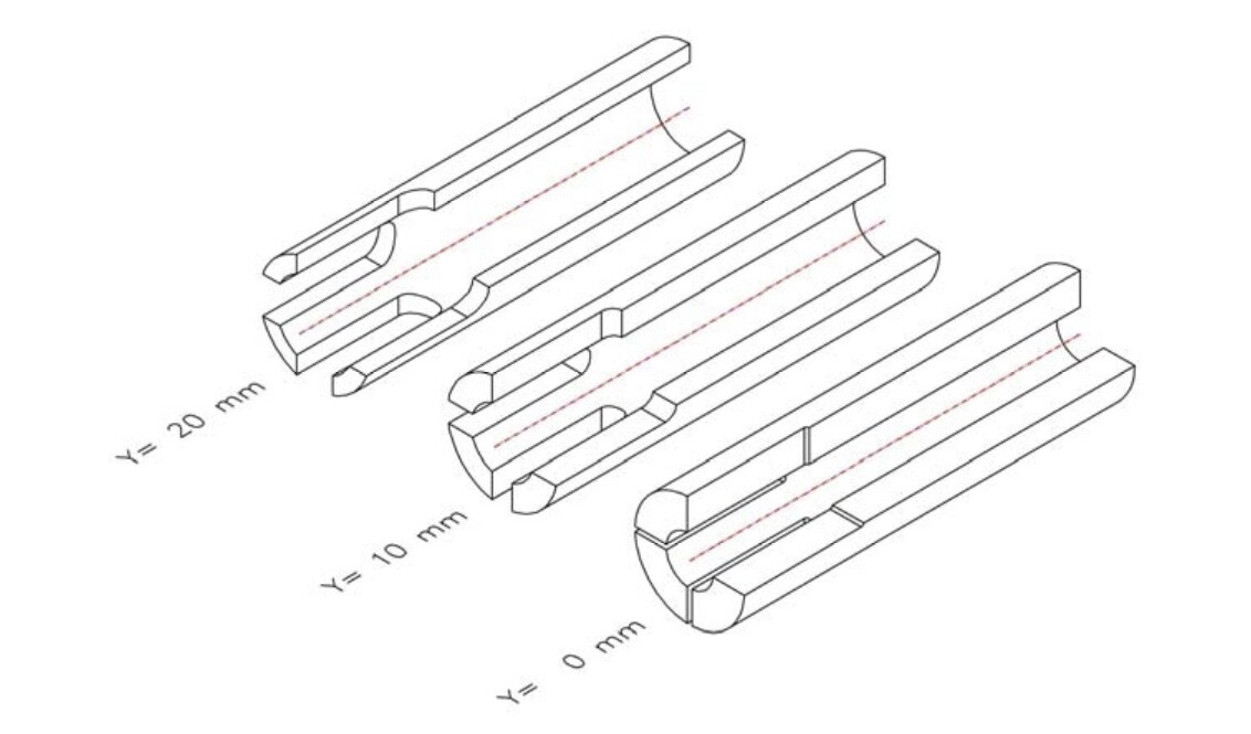
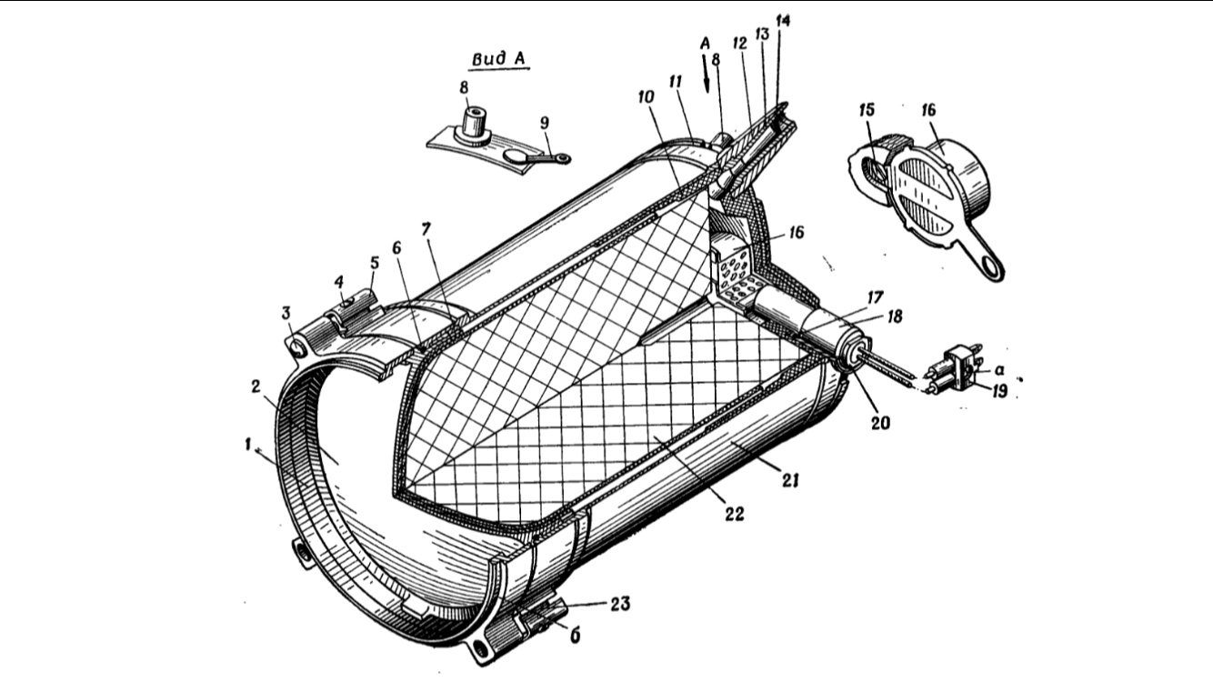
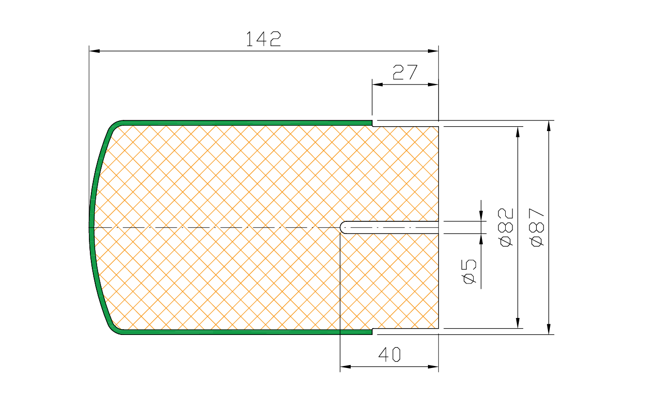
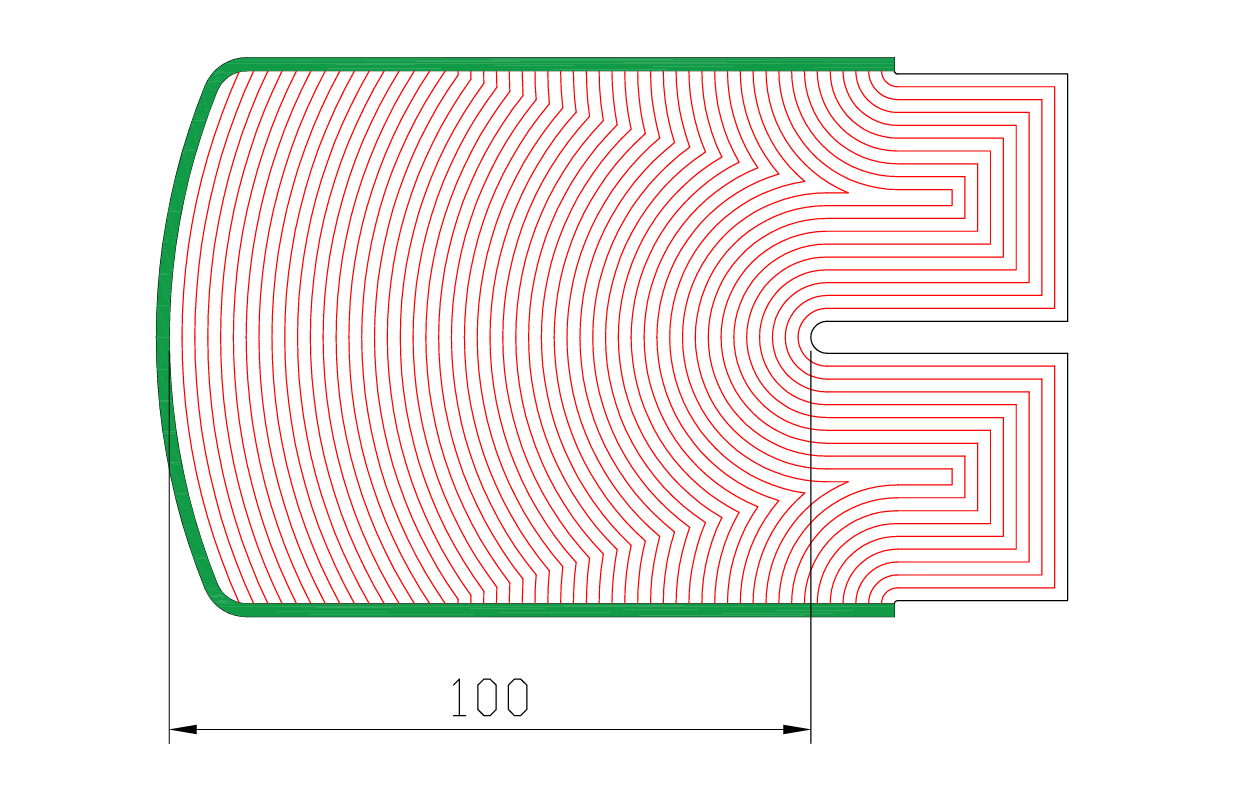
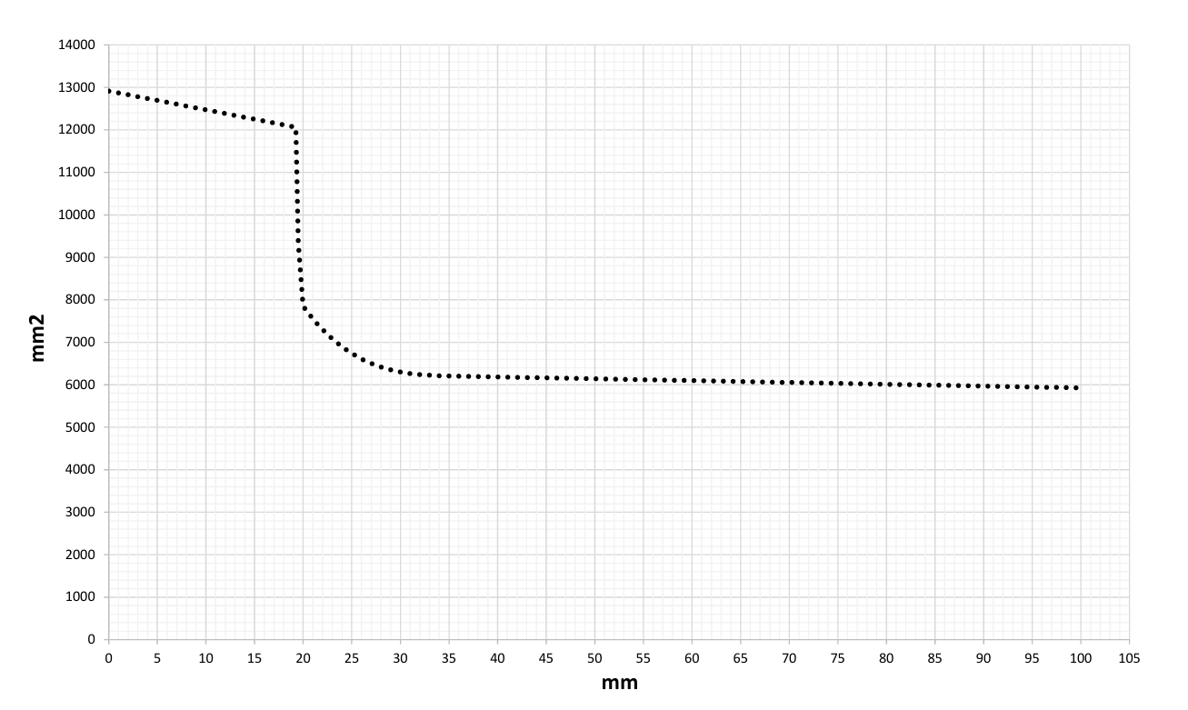
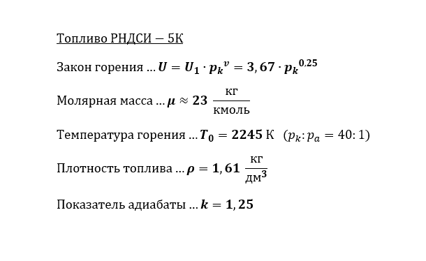
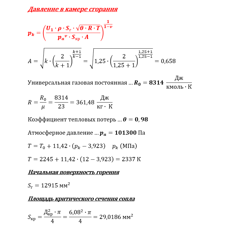
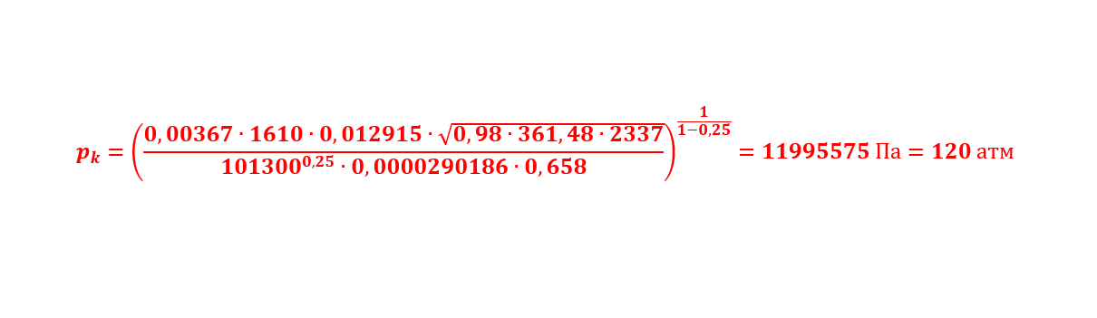
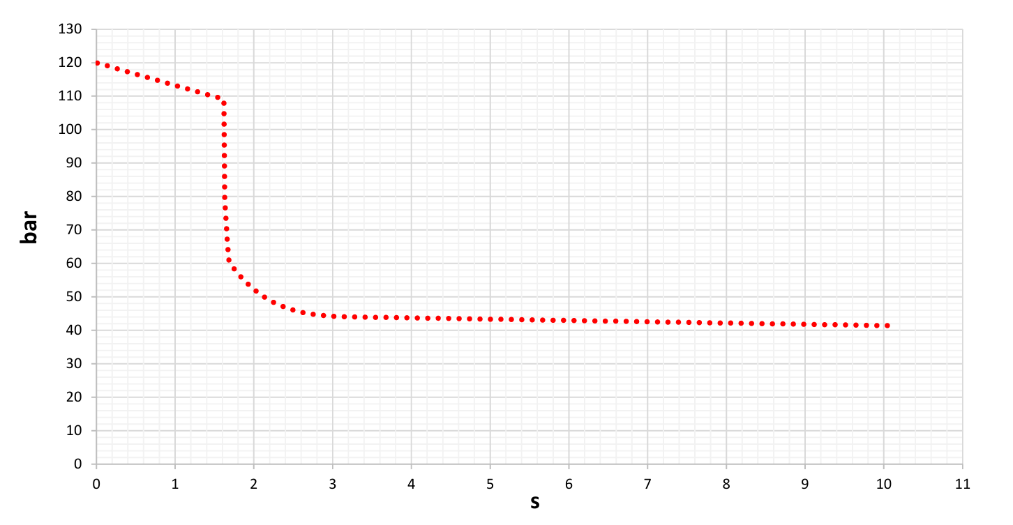
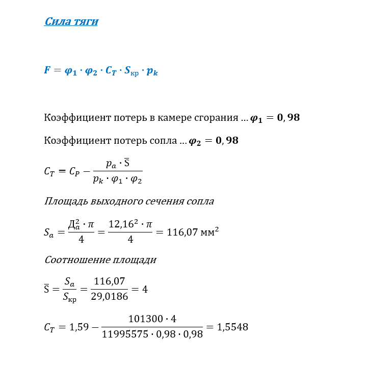
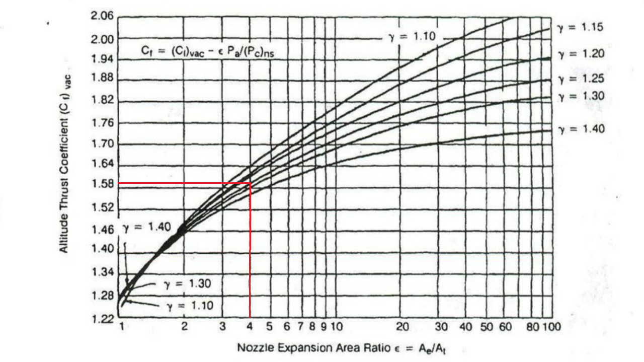
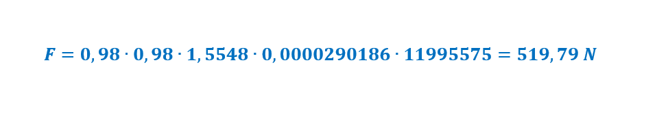
All right, let's make one, simply one but still interesting because it is dual thrust motor and values are not constant because of that so it is more interesting to work with Fagot 9M111 rocket motor -> It is with propellant grain which burns from back side, from inside starting in small pit hole and also partially from outside where grain is not covered with inhibitor. It has two sideway placed nozzles where each has throat diameter 4,3mm and exit diameter approximately 8,6mm. We can take these two nozzles and convert it in just one of course so it would be one with throat diameter 6,08mm and exit diameter 12,16mm. In any case nozzle is with expansion ratio 4 (De^2/Dkr^2) Beside that each of these two nozzles are declined for 20deg in respect to longitudinal axis and that will be needed at the end when we get to thrust force becuase we are interested in force component in longitudinal direction This is grain configuration and one of the most important things when trying to figure out how some motor works. It burns like said from back side and burning layers are like this This is where you guys, using 3D programs, would be highly helpful, for you it is just piece of cake to make such layers with offsets starting from initial burning surface. But it is kind of hard to find anybody interested in this. In any case and sometimes with lot of work, surfaces can be calculated and usually I start with that. To make function of burning surfaces in respect to one linear measure and because this motor burns longitudinally it is normal to use longitudinal base so that would be these 100mm And here it is, this is how burning surface change. For now time is still not included but form is here and similar form will be when pressure-to-time and thrust-to-time functions start to draw it self. Next is to find some data about propellant, and in this motor propellant is grade RNDSI-5K Just like geometry of grain, these data are very important, especially the first one, burning rate. Actually others are also important because wrong numbers can change picture sometimes significantly. But for most of propellant grades useful information are available and by that chances for making huge mistakes are minimal. And now the most important...pressure in motor On the top is formula how to calculate pressure in chamber. In this motor throat inserts are of molybdenum so we can take that there will be no erosion of throat so even throat area can be considered as constant so we have only two variables, burning surface of course and temperature. For RNDSI-5K temperature of burning is give as 2245K but it is when chamber pressure is 40bar. Here I gave one formula how to calculate burning temperature depending of pressure and that is what goes in integral calculation. Usually with some value of temperature we must start, and with steps of integration temperature will come to itself. I expect pressure to be about 120bar (12MPa) so temperature in first step will be 2337K and initial burning surface is 12915 square millimetres. Be careful with units and here is first pressure -> So, initial burning surface combined with everything else will make chamber pressure of 120 bar. That is first step of integral, and next is just same work until all propellant burn out. Now when we have first pressure, integral calculate burning rate at this pressure as 3,67*120^0,25=12,15mm/s. Small integral time step of course will give more precise results so I used time step as small as one hundredth of second, meaning in that time grain will burn just 0,1215mm and that is actually first offset which gives new burning surface which now goes back in formula of chamber pressure...and that is loop which started to roll on. Nothing complicated, I use just common Excel which makes all the work. The main problem and what is looking for most of time is to prepare function how burning surface change with all these offsets. After about thousand integral steps, pressure-to-time curve is born Next is based on pressure and nozzle geometry to calculate force thrust Here we have just one variable (pressure is also variable but it just jump in) and it is thrust coefficient Ct. Nothing special and really easy to understand, simply we need thrust coefficient for our specific motor and in our specific conditions. Motor is with now known chamber pressure, nozzle geometry is known, and we are looking for thrust at sea level where ambient pressure is 101300Pa. For that we need to have theoretical thrust coefficient for full expansion in vacuum For motor with nozzle expansion ratio 4 and for propellant with heat ratio 1,25 thrust coefficient in vaccum will be 1,59 but we need thrust coefficient at sea level with chamber pressure as it is, and it is 1,5548 with 120 bar inside. Shall I mention Phoenix with expansion ratio 18,5 and heat ratio 1,2 Now all numbers are here and thrust can be calculated, again like with pressure, steps of integral just drops numbers out At the beginning I mentiond that nozzles are declined for 20 deg in respect to axis so these thrust values must be corrected to get true longitudinal force which is cosine component of total force, meaning values must be multiplied with 0,94 (cos 20deg) so here it is, final thrust Put the rocket on the launch and here it is
-
It has sense, one without other is not possible So…if you are interested…shall we start with one sample motor, step by step…after that all others will just follow same principles
-
What exactly, rocket motor configuration modeling or calculation of internal ballistic?
-
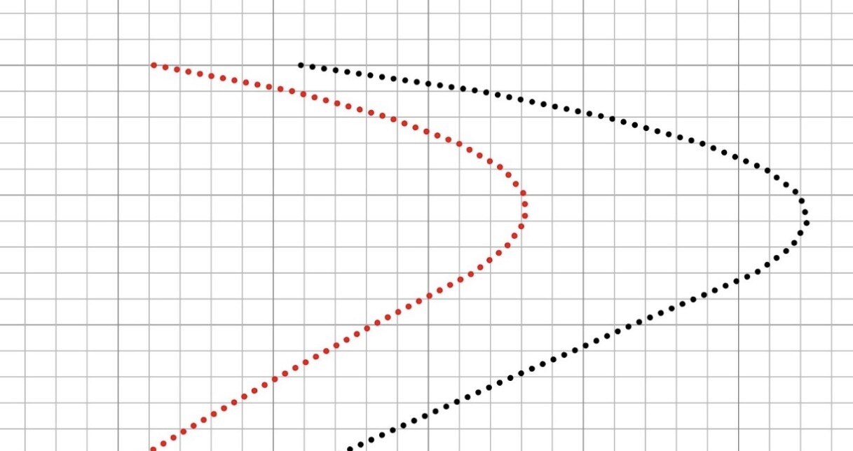
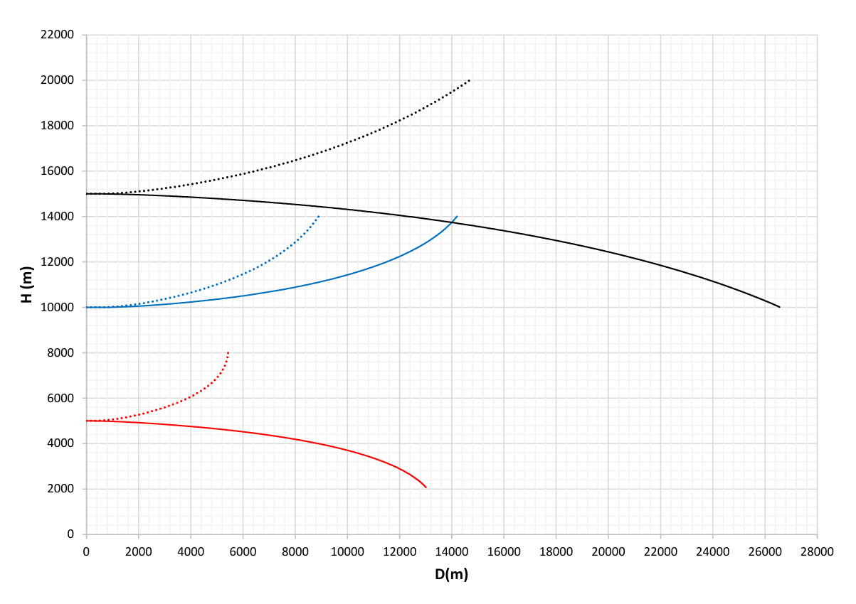
Several R-40 trajectories (without involving guidance method) Red line 5km 300m/s DOWN and RIGHT Red dots 5km 300m/s UP and LEFT Blue line 10km 400m/s UP and LEFT Blue dots 10km 400m/s UP and RIGHT Black line 15km 500m/s DOWN and RIGHT Black dots 15km 500m/s UP and LEFT
-
Просто информативно, не принимайте это как должное
-
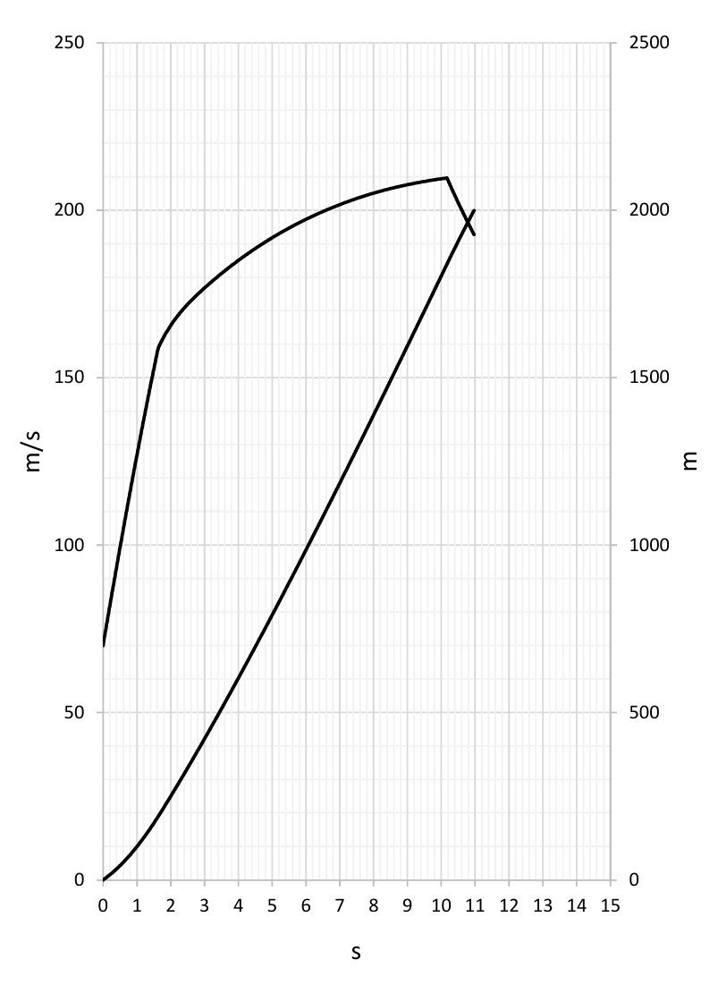
Расчетные данные для Р-40Р Коэффициент лобового сопротивления (угол атаки=0) Коэффициент подъемной силы (полый по одному крылу) Диаграмма скорость-время для 5, 10 и 15км с запасом перегрузки от три и шесть единиц (X-проекция полета ракеты) Диаграмма дальность-время для того же самого Это было просто, сложно определить, где проводить линии ограничений, не связанные с кинематикой…их здесь много насколько могу судить по тем книгам о Миг-25П
-
Хм…Р-40…почему нет, хороший выбор
-
After R-60M a bit about R-13M…do you even have R-13M in game !? R-55 could be next Рис 1.12 - Диаграммы для определения максимальных и минимальных дальности пуска ракеты Р-55
-
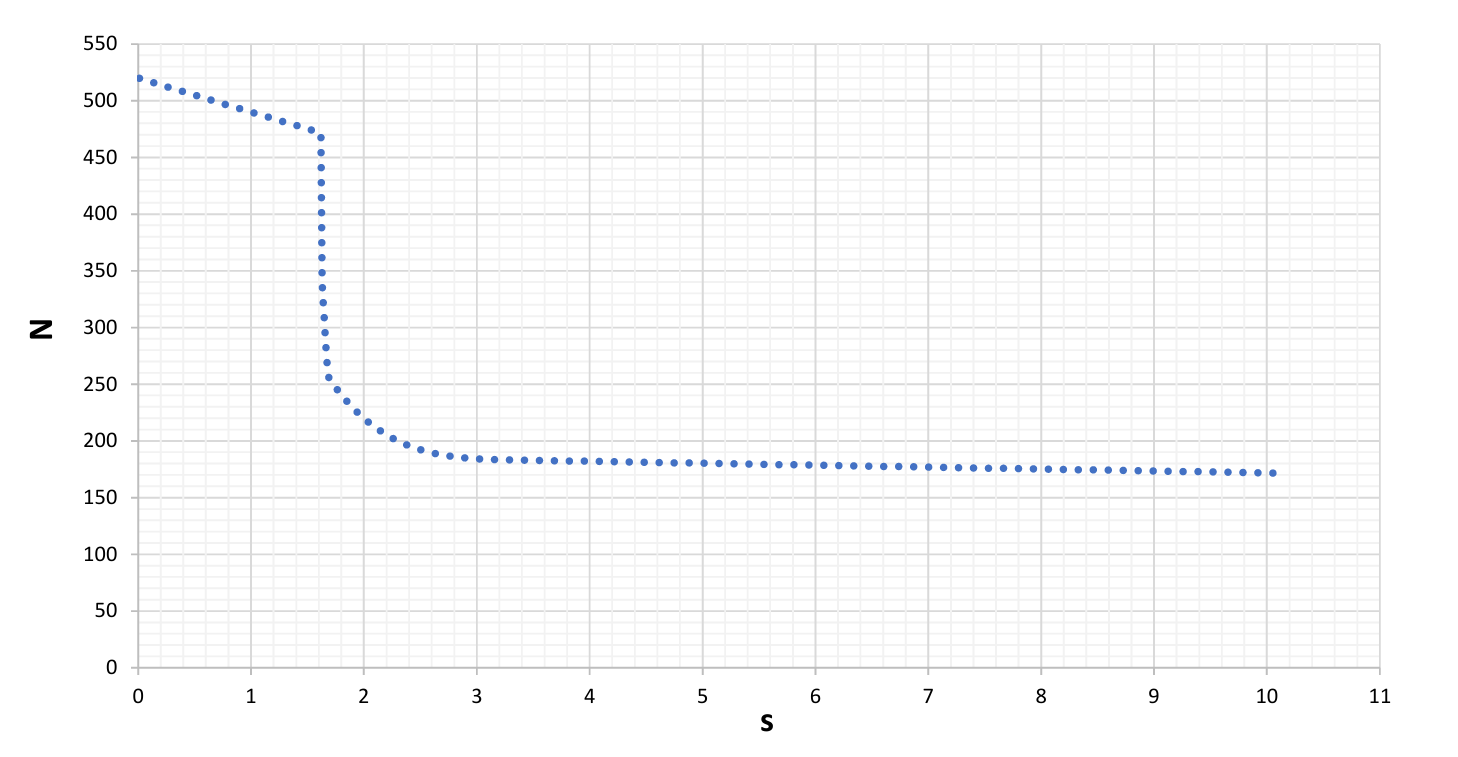
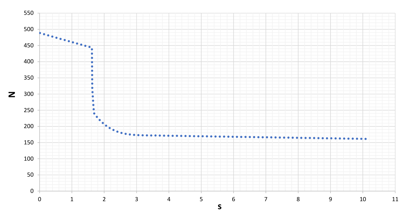
Kinematic of R-60M in few pictures Values are for 1, 5, 10, 15 and 20km Black dots are launching envelopes and red dots are rocket flight envelopes. Black lines of course various practical limits in altitude and distance…and after trimming familiar (in this case specific) shape of launching envelopes appears
-
Why don’t you for a moment forget hinge moments and advantages of grid in that, and just convert area of grid into classic fin and calculate lift coefficients (per degree) in function of Mach number Just like drag coefficients, lift coefficients as well I estimated for external ballistic of R-77, it would be nice to see is estimation was close
-
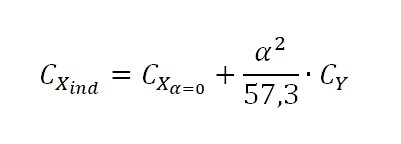
When we started all this, just to show with few numbers how much all that is complicated and variable. Drag coefficients Cx, without involving lift coefficients Cy, are not much relevant for complete picture Cxind-induced drag coefficient Cx a=0 -drag coefficients at zero angle of attack a- angle of attack Cy- lift coefficient per degree of angle of attack Just one of numberless cases…rockets weighting 120kg, flying at 10km where density is 0,4 kg/m3 with velocity 800m/s, and diameter of rocket is 0,2m. And let’s say flight is overloaded with 6G. One rocket is in configuration having zero angle of attack drag coefficient 0,5 and lift coefficient 0,3/deg while other has 50% higher drag coefficient but lift coefficient as well, so 0,75 and 0,45 respectively. Angles of attack for these two rockets and selected case would be 5,9 and 3,9 degrees. Now to see what are induced drag coefficients…0,68 and 0,87 respectively So it is not any more 50% difference…still 30% in benefit of concept with lower zero angle of attack drag coefficients but putting everything in lower density, lower velocities, higher overloading, cards will turn around and oops, on first view, less beneficial concept could become more beneficial
-
Comparison of R-77 (assumed motor) and R-27R in several cases: 1) v=400m/s ; H=1, 5, 10 and 15km 2) v=600m/s ; H=10 and 15km 3) v=300m/s ; H=1, 3 and 5km
-
It is not just simple as that. All this subject is actually very complicated Same area of wings, same placement of pressure centers, same arms of moments ... but lift coefficients significantly different because of ... I don't know english word ... за счет удлинения крыла. And in result, upper design in theory, in particular velocity zone, would have higher total lift coefficients and accordingly bigger available overload potential
-
I didn't calculate drag coefficients for R-77, just used estimated values -> for active and passive, ref.area body cross section Of course these kinematic is with included +3G reserve, with included induced drag due to angle of attack etc etc
-
Leveled flight...v0=400m/s and v0=600m/s From kinematic point of view, it goes very far indeed. Don't forget that over there in rear atmosphere drag is becoming to be not so significant...but what motor can give is becoming to be of very much importance...take a look at nozzle exit and nozzle expansio ratio which just push over there
-
If someone were to ask you, just out of curiosity, what would you say the total impulse at sea level would be? R-77 of course is subject. Any thought is welcome but of course in level of reality. Motor is created based on patents (always so much valuable sourse of informations)
-
What these border lines should present ?
-
From kinematic point of view and mechanical perspective, most of rockets and its trajectories can be, with basic knowledge, quite precisely determined…up to 10km altitude, maximally 15km depending of motor potential. Above this zone, circuses starts and most of linearity that could be used or counted on at lower altitudes, over there stops. Mistakes or better to say miscalculations measured in 15-20% just by overlooking some initially considered as irrelevant details can happen easily. Depending of nozzle and chamber pressure thrust can be significantly increased, depending of configuration drag coefficients can be significantly increased due to friction, atmosphere conditions if deviates from standard atmosphere, and it does normally, bring changes measured in easily 10-15%. With high altitude and rare atmosphere, angles of attack becoming bigger and bigger, and depending of rocket configuration this last is starting to be the first factor for determining zones. In these few “launches” of mine, stability was main factor for shortening zones, sometimes significantly and rapidly
-
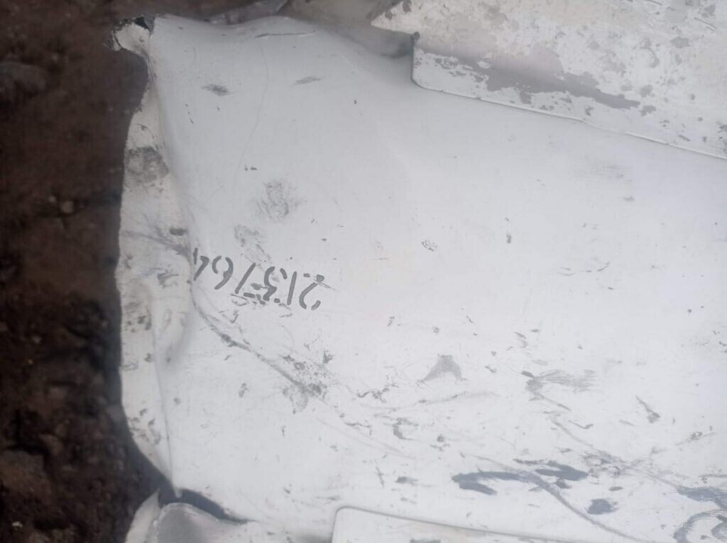
Ни в кармане, ни из кармана … but why students on prestige state military university learn about R-27P/EP if such rockets allegedly don’t practically exist in form air-to-air against maneuvering targets, I’m confused I have nearly close to zero knowledge about radars, pelengation, waves etc but this is rather strange, to waste time explaining them rockets, giving them characteristics, parameters, possibilities over targets etc and then…you know it was just a joke, such rockets are not possible By the way, this is what I mentioned few days ago, this is fragment of R-27 of some kind but 213….!!!???
-
2602894821235 R or T or ER or ET, old ones, newer ones, exported…where ever number can be seen it starts with 260…. Except one, based on details for me guaranteed related to R-27 family but it doesn’t start with 260. And it is used in combat Come on, be serious…internet is literally flooded with “secrets”
-
This about R-27P/EP...does anyone have some nice photo of those where serial number of rocket can be seen? Or another way, does anyone have photo of any R-27 with serial number which doesn't start with 260.....
-
Isn't it 3000m above target?
.png.47d31d77e8ae92f5040f8bc8235a6ce7.png)


.png.774a57f4eeb04e002df818e6a0e77133.png)
.png.a68bee6f59d849d929d65d92b8acc8dc.png)
.png.0a2adda78ecedc49ad117c52314bd7f9.png)
.png.99dc7f201a9d058f28a7811236e2b445.png)
.png.34e6e40a2f87252082c83382baca9d94.png)
.png.06a083afbfe3af311ed80ff9278e4da8.png)
.png.d8de09d9cde981e5778f92f93c7dd5cf.png)

.png.037420f93b520f59ccddbfb4bf8f1cad.png)
.png.14e016448c78413357eafc04a470a82a.png)
.png.05119a801a1a5b6101a680175cc9c601.png)