

tavarish palkovnik
-
Posts
476 -
Joined
-
Last visited
Content Type
Profiles
Forums
Events
Everything posted by tavarish palkovnik
-
Thanks @FoxAlfa for pushing it. If possible I would like to see three leveled flights at 10, 15 and 20km with launch velocity 600m/s. Seems we really read all those diagrams incorrectly Trajectories with dots are just leveled (straight, horizontal) flights, meaning N=1 Full lines are trajectories also leveled but with applied extra overload N=4. Seems all such Russian diagrams as standard, present velocities and distances vs time, where extra overload is added to missiles, something like 3G over 1G of target. Can’t be just coincidence, several of those have same pattern

-
@MA_VMF ты знаешь кто автор этого теоретического расчета по Р-24?
-
Many new things about R-27 family, at least to me, appear in the meantime. I forgot, I remember only 5/3 ratio, could someone remind me about DCS numbers behind 27ER motor, seconds and forces. My numbers from last year obviously were wrong
-
Excel program for R-27ER had a bug, found it when trying to get something, simply saying, angle of attack was not in calculation after 30 seconds Anyway corrected and replaced...try to apply 1G in vertical and 4G in horizontal plane and familiar velocity-time diagram appears -> Problem with those velocity-time diagrams for R-27ER and R-27R is that in most cases we don't know what they should present if just extracted from somewhere without explanations. This diagram for R-27ER I've tried to understand for many years, I tried lot of various cases, perhaps it is just this, velocity of overloaded missile. Only in such case missile can retard to these final velocities on altitudes where atmosphere is rare
-
To share here, because DCS forum and guys here watched all that fight and epopee that last three and half years, deserve it It started from these first attempts After years of digging and researching it stopped in this form and FINALLY after so many months and years, this motor is DONE, it’s CLOSED THIS is that freaking motor of R-27ER, finally all puzzles made its place. It took three and half years, but joy to see it finally is bigger than all troubles this motor caused. I know this will be strange to most, but the ones having strong passion for something, they will understand
-
Empty...try one more time, maybe I accidentally deleted it, I had to delete lot of things to make attaching available again...perhaps only forum with such limited available size
-
I don't know what is MCA, but it can't be constant especially with motors having high expanded nozzles such R-33 and especially AIM-54 have
-
Энероговооруженность is very trivial term and characteristic. This is model which starts from chamber pressure and nozzle expansion ratio, and depending of altitude and atmospheric pressure, force of thrust is change from second to second
-
What is energy capacity ? You can write in Russian, I will understand, only writting is difficult
-
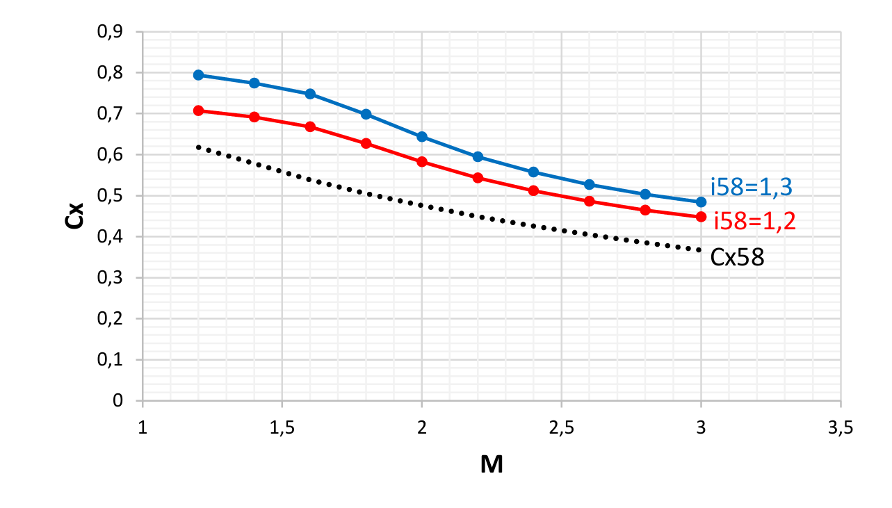
Anyway...Excel program with predefined R-33, you can move it up and down, aslo aside in perimeter, you can choose i58 as well athough I'm quite sure drag coefficients are in range of 1,2-1,3 (i58 of Cx58). Have a fun with launching it all over …. Come on, you are taking me for 2,5% in total length while you take nose to be 1,5 times longer the it is
-
...
-
2,368 to me...900/380 This is more preferable to me
-
OK, thanks @MA_VMF You know I'm old school and I like to question everything, that's why that comment came from. No, I don't doubt in possibilities of softwares but the fact is that your results are in huge disscrapency with some old basic theories about this fluid dynamics Here are only two subvalues of total drag coefficient at 2M, nose pressure and base pressure, and sum of those are higher then you total at 2M !? Where you lost everything else, where friction went and pressure at wings !?
-
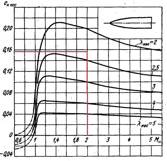
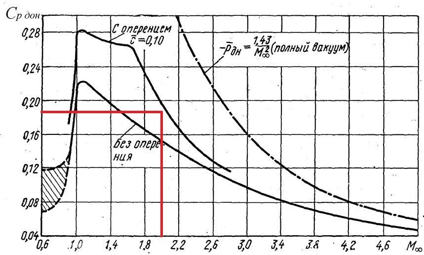
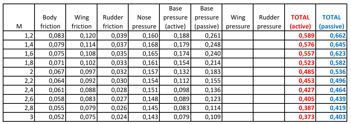
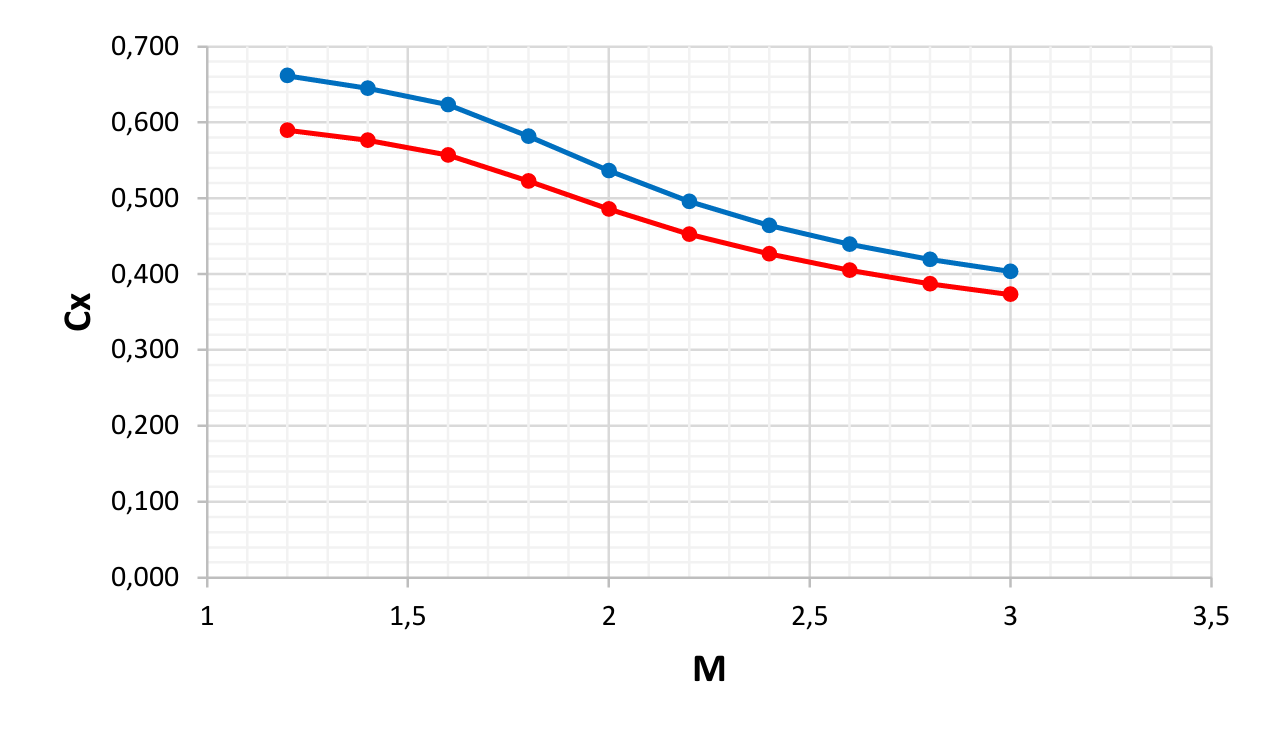
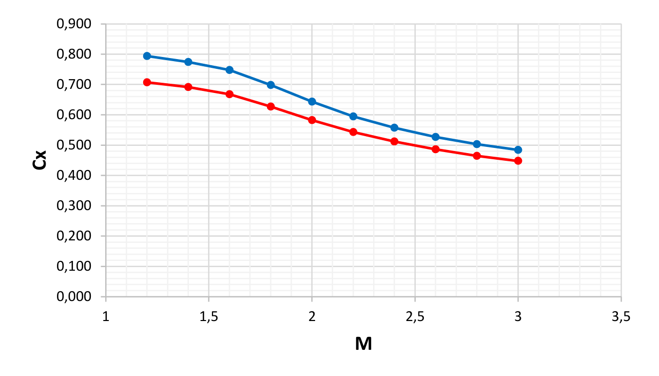
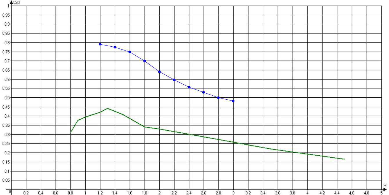
@MA_VMF nice work, only you didn't give us what is your reference area for this drag coefficient function and is this for active (motor works) of passive stage If your reference area is body cross section then I think you have some mistake. I will try to show in few steps how much I would give to R-33, don't have time for deep calculation so some parts which are usually difficult (pressure on wings) I will just add as extra increasing factor In total drag coefficient for this configuration 7 subvalues participate, 3 of them from friction and 4 of them are due to pressure. Total sum is as presented in red for active (motor works) and blue for passive. As you can see, for example at 2M, only nose and passive base pressure (together 0,34) is more then you gave as total...if your reference area is body cross section To make it easier I just increased these total values for 20% (adding pressure on wings and rudders, also negative influence of various factors increasing drag coefficient like launch hooks, antennas etc etc) and final functions could be something like this So passive drag coefficient with body cross section as reference area incorporated in your graph would be like this In any case, I will make program for R-33 similar like for AIM-54 so you can launch it how you like and how long you like, and just to explain right now because I will add it in section of inputs. How I use drag coefficients...always based on Cx58 function, it is Russian standard function and drag coefficients for specific rocket are defined with i58 factors. So when i58=1,2 it means average drag coefficient is 20% higher then standard Cx58. It is how it goes, Cx function is in program base and i58 defines drag coefficients
-
@Katsu gave me energy not to gave up of this Phoenix bastard and I will not. I made few programs recently and one I would like to share here, it really, like I used to say, plasticity shows what is behind of this awkward motor @Маэстро @Chizh I’m sure you guys have force to intervene, to influence, to change it, to make all those guys complaining to be satisfied. Or simply to change injustice done to Phoenix motor which is momentarily ruined…strange of someone who fancy “red” side propulsion concepts to be so persistent for improvement of “blue” side motor, but simply it deserves that because of its unique design, it is really one of kind. Recently I spoke with one engineer who worked in Rocketdyne decades ago, not exactly on this motor but he knew the guy who was I believe creator of this specific and unique design. And Phoenix motor was indeed conceptually with two slots in grain and it was so much regressive because of mission needs like he said. I was thinking and trying to understand this last, what exactly that could be. … This is just simple Excel program, customized for Phoenix, while motor works and for vertical plane displacement only because changing of altitude (ambient pressure) is the most important for figuring out how this motor worked. Initial velocity, altitude and pitch is of course open to change and then with applying overload missile can be directed in trajectory as per will. Angle of attack is respectively calculated, and for anybody playing with this, don’t push it to hard, otherwise missile’s nose could flip over, 15 degrees should be enough. Max altitude and max velocity is just because of in program inserted database. But what just poke eyes is linearity of specific impulse when missile is pushed in loft. No matter of regressive thrust and regressive mass flow, with lofting specific impulse values (exhaust velocity respectively) becoming linearly constant. I even believe this could be used for determining how loft trajectory is actually programmed with Phoenix, depending of launch altitude loft could be such to keep specific impulse constant from some reason necessary for mathematical model of inertial navigation. Not sure in that, but fact is that with majority of applied lofts with regular overloads, specific impulse has tendency of linearity and constant value. I know your models are with linear constant thrust only, but even with using such average values depending of altitude, divided in few groups of altitudes, model would be significantly improved. Phoenix deserves it, concept was indeed interesting, in theory it worked well, in practice engineers have been faced with many technological problems. Unique motor in any case, different to all other tactical motors of that time, and before and after, so it would be nice to give respect placing it on right place
-
Это зона возможных пусков, не зона поражения цели и не зона полета ракеты
-
Так написано, зона пусков с перегрузкой цели от 4 до 6. Если посмотреть на скорость ракеты на конечном этапе, то эти перегрузки цели кажутся правильными
-
@Katsu don’t make them to lock this thread as well and I know they won’t because these guys here are better kind than those ones of “canceling culture”. But never mind, all what had to be said is said and if those HB or whatever companions still want to live in their illusions and some imaginary not existing source, then they can live in it. Unbelievable guys and so shallow in subject which they should know much better in any case
-
A bit more about impulses, nozzle expansion ratios etc etc. Once upon a time Phoenix in DCS if I'm not wrong, you guys will confirm, had specific impulses in range of 250s. Internet said it is specific impulse of CTPB and HTPB types of propellants and how not to accept it. However, there is so many behind it and simply it was wrong. Developers either figure it out alone, or somebody draw attention to them or simply with time some documents of various motors appeared where miraculously specific impulses were more about 230 than 250 and propellant inside were CTPB and similar. Hmmm...what to do now...all right it will be 230 or something like that in Phoenix as well...wrong again Let's see something about these AP aluminized propellants with polybutadiene rubber as binder. Here I drew two RDS propellants, one with 14% of aluminium and 69% of ammonium perchlorate and second with 4% of aluminium and 82% of ammonium perchlorate. This second one is what I believe similar to what was in Phoenix. So these are theoretical values of specific impulses for such composition, maximal values, but only if ratio between chamber pressure and atmospheric pressure is 68. This is from American literature so it is chamber pressure of 1000psi vs atmospheric pressure of 14,7 psi (1000/14,7=68) or 69 bar / 1,013 bar. Russian standard is 40/1. All right...maximal theoretical specific impulse for 4% aluminized CTPB would be 250s. We need not theoretical value but delivered value, what exactly nozzle gives, and it is hard study, but generally bigger percentage of aluminium is always with bigger losses or better to say with lower nozzle efficiency. It is not huge difference but few percent and for 4% it shouldn't be more than 1 or 2%. Let's say 1% so delivered specific impulse would be 247,5s ... again ... only with ratio of pressures as 68. Some imaginary motor with chamber pressure of 69 bar to fully expand all to the atmospheric pressure of 1,013 bar needs to have nozzle with expansion ratio of 8,8. I don't have diagram for 8,8 ratio but this one for 8 could be easily used. What we see, if chamber pressure would be 1000 psi (69 bar) such nozzle at see level (atmospheric pressure 14,7 psi or 1,013 bar) will deliver specific impulse of something like 245s. Great, that is what we need. By the way, this delivered specific impulse is also with additional reduces, major reason is losses in divergent zone, again only about few percent we are talking. You can see that on these 3 nozzles and 3 chamber pressures, delivered specific impulse at see level vary a lot, from 220 to 250s but neither of these 9 cases, except marked one, is full expansion, either over expanded either under expanded nozzle. All right, so nozzle should be with expansion ratio 8,8 that chamber pressure of 69 bar fully expand to 1 bar That is case of these ''red'' marks, and this Phoenix propellant like most of other similar propellants is with heat ratio of 1,2 or very close to 1,2. This is perfect, line of 8,8 nozzle expansion ratio and curve of pressure ratio 69 perfectly hit curve of optimum. Let's see Phoenix with its 18,5 nozzle expansion ratio. To hit curve of optimum chamber pressure should be 175 bar to have full expansion to atmospheric pressure. Chamber pressure is not even close to 175 bar but average pressure is something like 46 bar...take a look how much it drops in overexpanded zone at see level. Thrust coefficient is only 1,4 ... 1,4*4,6*55,372˄2*3,14/4=15500 N ... looks familiar isn't it ... actually now I remembered that it was 45 bar in my calculation but it doesn't matter or change things in principles. I've already showed how much this motor is different from other motors of tactical missiles, this is just other form of same. This ''blue'' area is where most of other motors fit and take a look how much Phoenix is far a away of that. For questions at disposal of course, what ever is in my power and level of knowledge I will try to explain. This has nothing with sources but just common theory of rocket propulsion, sorry guys but without this it will be hard to understand how Phoenix motor worked
-
Roger out Discussion (argumentation) will be continuing…only technical of course
-
OMG…you guys are really unbelievable. NASA handbook is from 70’s and do you really think you could just go to any library and get same in that time !? It was for their use only, that should be perfectly clear to anyone reasonable, and by that still classified enough. But even that, still they mentioned that classified data from CPIA were not disclosed. Of course decades after that, handbook is publicly available and so we have it now. Same with W.T.Brooks paperwork, it was presented back there in 70’s again just to small group of engineers on those seminars where they were exchanging knowledges…same like handbook, do you really think that Peter Pan and Donald Duck have entrance to those meetings!? But let’s break this chain, this layer’s arguments I don’t buy, I’m engineer and by that with different postulates. So I still haven’t got any dispute of technical matter while your model is full of holes in foundation so I will continue to shake it
-
Fair enough although I didn’t ask anything from you regarding your source. Just to point with what you don’t agree presented here. Is it NASA nozzle handbook (extremely helpful data) or W.T.Brooks paperwork (same if not even more helpful data). These two sources just made Phoenix motor to “drew” it self, like said, literally.
-
Sorry but me again What exact source or what sources are not so trustworthy? Here in all this gymnastics of finding answer, there were several sources. Some gave geometry, some gave weights, some nozzle details, some thermodynamics parameters etc etc It shouldn’t be, I hope so, that all are questionable to you. Which one/ones is/are debatable?
-
After “trusting method” of determination something strictly of technical matters now it is “believing method” and turned on my side @Naquaii may I ask, with what exactly you don’t agree? More than detailed I tried to explain every step of finding numbers behind this motor, everything is presented, nothing hidden so it shouldn’t be tough to point on, what exactly is that makes you not agreeing. Or if there are several points, no matter, I would gladly repeat with extra explanations
.png.fa22be12f5607104ad4f57ed7ffaeaeb.png)
.png.d469f7592449ef4ac191ba12e4a4a491.png)
.png.19350cf152036fcd2a0832b769a5c0e5.png)


.png.5b71a734f8c6bbbe38a37c86b70ce790.png)
.png.bb75e81fc1aeeaaccb568e8bbefa8702.png)
.png.ff8e123c366ea66c99b0984ea22cc1e9.png)