tavarish palkovnik
-
Posts
291 -
Joined
-
Last visited
Content Type
Profiles
Forums
Events
Everything posted by tavarish palkovnik
-
Can't agree with this...thrust ratio for 27ER of 5/3 simply is wrong, unachievable for concept of this motor. I know I'm going on nerves with this but it must be said. It has finocyl grain, slots are 800mm long, it has initial burning surface and it has final burning surface and we all know how finocyl burns End is clear, can't be anything else than this and estimated burning surface is easy to get. Initial burning surface depends how many slots are in grain of course, but 8 such slots give the most natural behavior. Thrust depends of pressure, pressure depends of burning surface (beside many other things of course) and ratio 5/3 is in simpliest way said, just wrong

-
Wrong in video and ILS presentation how this fight was going on, or wrong in description of mine? It was long time ago when I was interested in this so I forgot, does KOLS can be merged with radar?
-
To copy here text I wrote last year on one other topic when this video appeared on the net: “Few days ago new source of information appeared, nice view of launching R-27ER seen thru ILS (HUD). Helpful for additional determination of actual and real behavior of this rocket.Shortly to express what I see here. Fighter (Mig-29) fly with nearly constant velocity of 150m/s at altitude of 600m. For almost 20 seconds, from taking target in lock-on through PR time (launching allowed) till rocket is launched, indicator of mutual distance (distance between fighter and target) stays still on some let say 1,5 km. Title of video says target was Orlan what can’t be true but something that flies with nearly same velocity as fighter. Don’t thrust everything on Internet.With multiple trying I managed to count 4,7 seconds for rocket flight time, plus minus.So how much rocket flew in those 4,7 seconds? Taking roughly 2200 meters, 1500 meters initial distance plus what target added with its continuous flying at 150m/s.If rocket’s flight would be considered as constant acceleration moving then acceleration can be calculated roughly as 135 m/s2 and final velocity as 785 m/s. Of course due to drag it will be less but for rough visualization it is all correct.Now what interest me the most. What is force needed to give mass of 350kg such acceleration. Newton law of course, F=m*a and it gives average force of 47250 N and total force impulse 222075 NsIn these 4,7 seconds I’m giving to motor to operate at average 80+ bar pressure so delivered specific impulse for such nozzle down there could be something about 250s.Next step is determination how much fuel roughly should be burned in these 4,7 seconds. 222000/250g=90kgWith adding time of starting, erosion, to move rocket from launch pad, to compensate losses etc for 4,7 seconds 95 kilograms of fuel should be burned out, and rest 45kg of available is to keep pushing. I’m giving 20kN thrust in sustaining phase in same time, 20000*4,7/45=215s making average 230-235s what is so natural and so normal for such nozzle at nearly sea level.” By the way, in addition to say that in the meantime few motors I was trying to figure out, including R-27ER, R-33 and H-58 went through redesign and got 8 slots what gives much more natural burning behavior
-
Aviation Archives: MiG-25PD Flight and Combat Employment Training Manual
-
It would have much more sense that scale is in km but scan said in m. Perhaps it was by translating bad copy, like said meters would be insignificant, kilometers would make something but still in comparison with X axis Z is not significant for what I’m interested
-
You are welcome! That should be third axis of Cartesian coordinate system, slight declining from ideal and straight line of sight. Most likely, because they took this matter seriously, due to like they wrote, errors caused by wind, initial aiming errors, off-center thrust, inclined rudders etc. Don’t claiming, just assume it is about although declining value is really insignificant, but presenting of trajectory in horizontal plane should be for sure.
-
Really no-one ? Meanwhile I found how China (Shanghai Aerospace) back there in 1997 estimated kinematic of HARM, seems very resonable ''Curves showing changes in motion trajectory and speed of ARM over time when attacking guidance radar'' AGM-88 HARM.pdf
-
Any volunteer with 3D modelling skills, for work together on HARM motor? It is kind of complex form for 2D taking burning surface measurements. 3D model would be very useful, step by step integration, initial surface-offset for calculated burning web-new surface-new offset etc etc...and several dozens time same activity Of course if result will be awkward, everything from the beginning Roughly but really roughly this is form that is expected to be
-
No, dog-bone should not be in sustainer, these two radial cross sections are more ''booster grain on sustainer side'' and ''booster grain on nozzle side'' as it looks like in longitudinal cut. Otherwise motor would explode becuase roughly calculated pressure would go in range of 300 bar. This could be normal motor after all
-
HARM, AGM-88A…is there any solid data about motor, whichever? Length is 83,5” and propellant weight is 280lbs, that is what can be found. Also propellant components As well as some kind of maximal velocity as 1937ft/s (590m/s) but behind this number everything be hidden. But is there anything about burn time or pressure rates, either in boost or sustainer? This should be cross sectional view of HARM motor but confusing one. Two radial slots are understandable, booster grain with gradually toward nozzle expanding dog-bone also. But what about sustainer grain, longitudinal cross cut shows it as cylinder and radial as dog-bone as well !? Two configurations changing outcome in all ways. Without radial slots and with tubular sustainer it would looks similar to Mk-65 of AIM-7F but if sustainer is also dog-boned then this dual thrust motor is somewhat different
-
Link to the site with freshly published flight and combat MiG-25P manual, on English and allegedly for Iraqis dated back in 80’s. There are some basic data about R-40 as well, could be interesting https://aviationarchives.blogspot.com/2023/12/mig-25p-foxbat-flight-and-combat.html?m=1 In addition also pressure-to-time curve of Maverick’s motor. It is a bit different to usually circulating data on the internet, and with this pressure data and with known nozzle geometry, thrust-to-time can be easily determined
-
No…it is now about AIM-7F and it’s motor Mk58 only I don’t know where to write about it … sorry, I know this is not place for it.
-
From -> It is 5096/807 lbf vs mine 5148/790 lbf
-
After quite number of working hours I have something to show regarding these motors, Mk58 actually This is concept, of course familar to all, it has two grains with different burning rates. It is not easy to calculate such concept, in way of making program to do all the math when propellants are not same. I guess booster grain is a little bit denser, but to make it more convinient I used same density for both grains and for this geometry it should be 1,75 kg/dm3 to have total of 61,5 kg. Further more, burn rate pressure exponent...for booster grain it is irrelevant because this grain will burn only in one regime, but for sustaine grain this exponent is crucial. If sustaine grain will be with pressure exponent 0,3 than all what is subject to match will fall in water. Sustaine fuel recipe with exponent 0,3 to have faster burning will lead us to pressure way above of targeting 20 bar, 30bar+. It is always a*p^n where ''n'' is exponent in burning law and with ''a'' burning rate can be adjusted (of course in level of feasibility) I used 0,77*p^0,45 for sustaine grain and 1,89*p^0,45 for booster grain, ''p'' in bars Slower burning sustain grain with exponent 0,3 will not be much useful in booster stage and also it would extend burning time way over 20 seconds in total. Anyway...this is how this should burn, isochores of burning surfaces And this is what I get -> It is someting about total time of 16,5 seconds with 4,3 seconds of booster and 12,2 seconds of sutaining mode. Average chamber pressures 124/22,3 bar (1798/323 psi) average thrust 22900/3515 N (5148/790 lbf). This is fuel consumption, about 40kg (88,19 lbs) in booster and 21,5 (47,4 lbs) in sustain Why it is not 5750/1018 lbf !? Americans have some strange and awkward method when presenting these thurst numbers, and when ever chamber pressure is close to 1000 psi (69 bar) and when ever full expansion through the nozzle from that pressure is close to atmospheric pressure of 14,7 psi (1,013 bar) it is OK, but when something other is case, like here, presented numbers are not real or true numbers. Just shortly on this sample... Isps could be 250s, standard 69:1 specific impulse. Cfstd is standard thrust coefficient for 69:1 and for k=1,2 and with nozzle expansion ratio 6,2 it is 1,584 Cftest...this should be thrust coefficient for real chamber pressure and for full expansion. Booster...it is chamber pressure 124 bar, full expansion will be achieved at sea level (1,013 bar) and thrust coefficent is 1,624 so total thurst will is 250(s) * 9,81 * 1,624/1,584 * 40(kg)=100577Ns and with 4,3 seconds thurst in converted style 23390N (5259lbf) Sustainer...it is chamber pressure 22,3 bar, full expansion through nozzle with ratio 6,2 will be achieved if ambient pressure is 0,53 bar (atmospheric pressure between 5 and 6 km) and thrust coefficent there is 1,527 so total thurst will is 250(s) * 9,81 * 1,527/1,584 * 21,5(kg)=50831Ns and with 12,2 seconds thurst in converted style 4166N (937lbf) So 5259/937 lbf is closer to 5750/1018 lbf than 5148/790 lbf If numbers 122/20,7 bar ; 3,69/10,86 sec ; 38,46/21,86 kg will be used than it as follows: 250(s) * 9,81 * 1,623/1,584 * 38,46=96646 (Ns) / 3,69 (s) = 26191 N (5888 lbf) 250(s) * 9,81 * 1,528/1,584 * 21,86=51716 (Ns) / 10,86 (s) = 4762 N (1071 lbf) It is not easy, it is quite complex but for sure I know Mk58 does not gives 5750/1018 lbf as true force
-
It says nozzle exit diameter is 3,78 inches (96mm) Also that throat area is 1,81 sq.inches so throat diameter is 1,518” (38,56mm) 96^2/38,56^2=6,2 what is nozzle expansion ratio Today I was doing lot of “mental gymnastics” about all these numbers, not sure but perhaps I managed to make some basis for Mk58 relatively to presented numbers. In coming days I will show it, perhaps even tomorrow if everything fits.
-
There will be plenty of work because just like in case of Phoneix motor, Internet is, for these motors as well, full of contradictions This specification here is example, simply these numbers are in mess There are pressure rates, there is nozzle geometry, all what is needed to define thrust in the most precise way. Boost 1769 psi (122 bar) ; sustain 301psi (20,7 bar). These number seems as reasonable and correct. Mk58 is motor of really complicated concept and it is not easy to make some calculations without having exact data for propellants. This what is written in table above is not enough, 12,7mm/s at 69bar (1000psi) is obviously for booster grain, at 122bar it would be with 0,3 burn rate pressure exponent 15mm/s and geometry follows it well, 4,5 seconds x 15mm/s = 67,5mm what is web of booster grain actually. But for sustain grain we have nothing. By the way, this burning time is strange and I think result of ''tuning'', I would rather stay at 4,5/11 seconds as stated in well known document about AIM-7F. Mk65 is for me of much more convenient design Unfortunately there is no cross cut view in full length so we don't know exact length ratio between cylinder and slots, but for example in this length ratio and for 4,5/11 seconds burning time, pressure ratio 122/21 bar with same nozzle geomery is achievable without any problems. Both motors, Mk58 and Mk65 should have same or very similar output of course. So if we take pressure data as correct, we have nozzle expansion ratio as 6,2 and let's say heat ratio is 1,2 (very sure it is, most of US propellants of that time is with such ratio) Thrust coefficient is boost is 1,63 and in sustain 1,37, nozzle throat diameter is 38,5mm. Now all what is needed to calculate thrust at sea level is here. There is also info that half angle at nozzle exit is 15deg so thrust loss can 0,98 -> (1+cos15)/2 Boost -> 0,98*1,63*12,2 (MPa) * 1163,56 (mm2)=22675 N or 5097 lbf Sustain -> 0,98*1,37*2,07*1163,56=3234 N or 727 lbf Not even close. What about thrust at 20000ft (6000m). Over there thrust coefficients are 1,65 and 1,53 so thrust would be 22955 N/3611 N or 5160 lbf/812 lbf ... still nothing close but those are real numbers if pressure rate is correct. This is for start...there is still lot to say about this
-
Motor or motors because there are plenty of those. Mk38 Mod.0,1,2 Mk38 Mod.3,4 Mk52 Mod.1,2 Mk65 Mk58 First three groups are with similar (nearly same) output and different and/or nearly same concept. Last two motors are with similar/same output but completely different concept. These last two are interesting because numbers circulating behind it on the Internet are just like in case of Phoenix very tricky
-
Finding answers how Phoenix’s motor actually looked and worked was with lot of fun. Is there some other motor of US or Russian origin which might be interesting, or which is with questionable current numbers, to strip it down in free time reserved for nerve relaxation
-
Grandpa Tsiolkovsky laughs from his grave, 90 years after he passed away, when he sees how some still try to dispute his theorem
-
Semyorka and Soyuz are conceptually same, technics of 50’s, and fun fact, today’s astronauts Russians, Americans and others still lifting their “assets” in space using technology from 50’s because it is reliable, safe and without marketing exaggerations
-
Actually it is at square of speed Imaginary case AIM-54 vs R-33 at 1000m, level flight And square of speed is here in so called dynamic pressure Neither of these two missiles is champion down there, but Phoenix because of its motor really sucks there
-
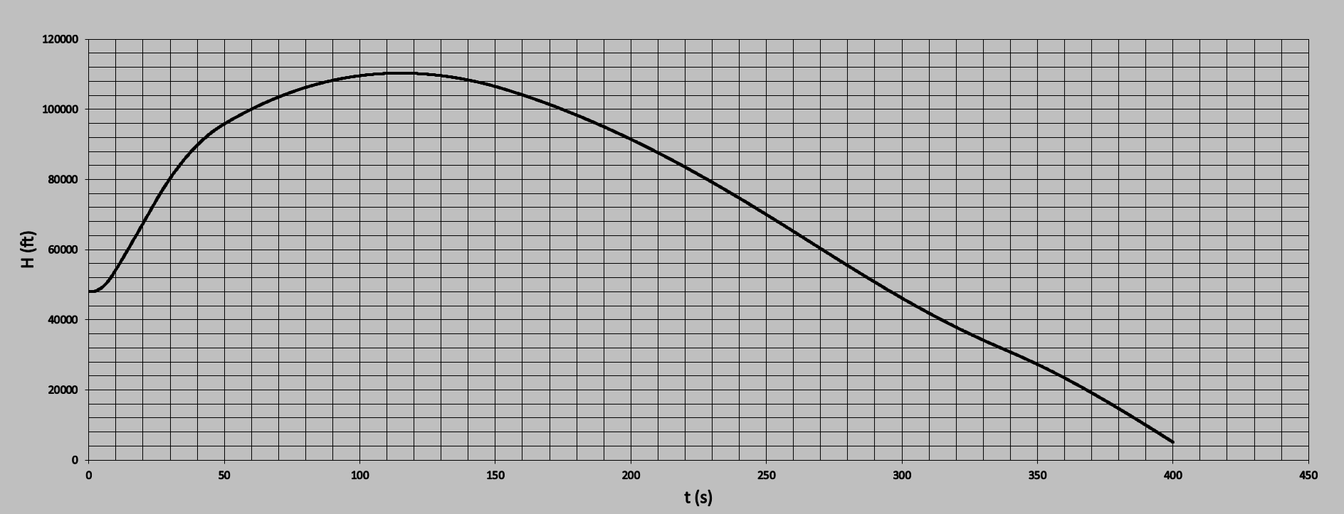
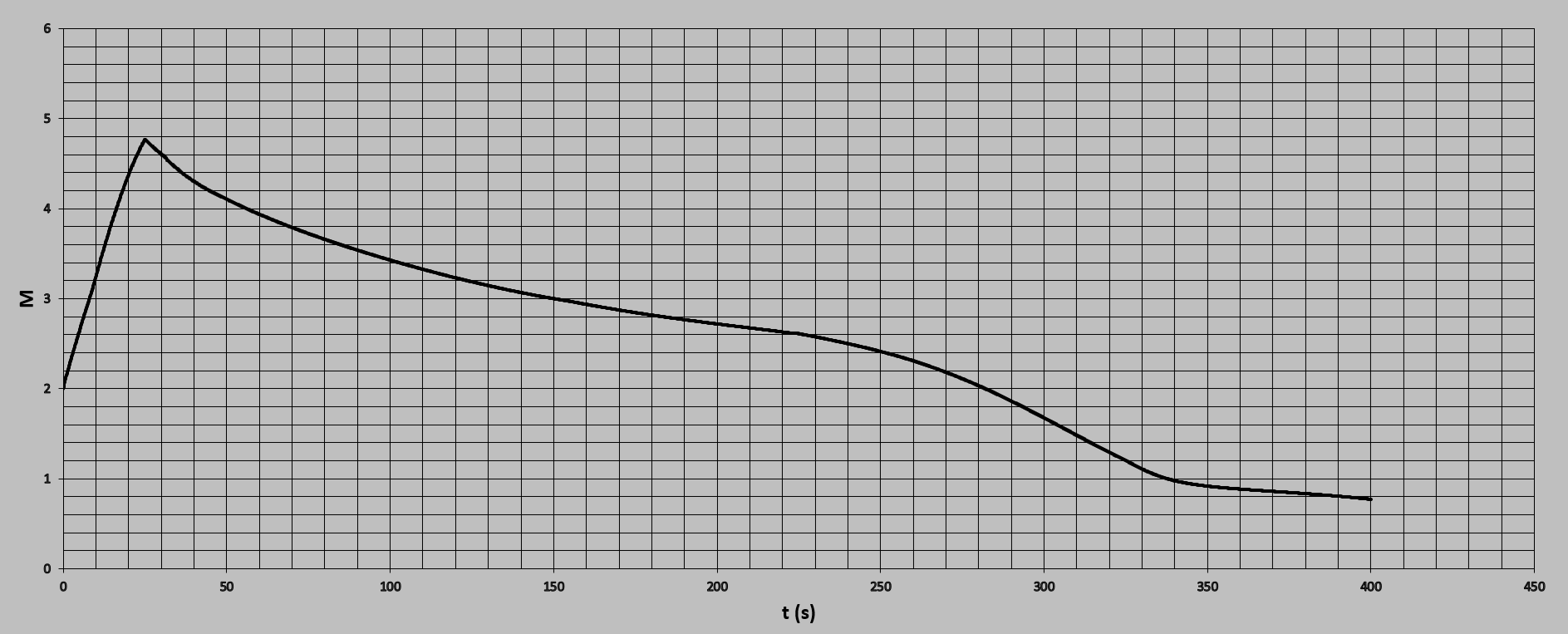
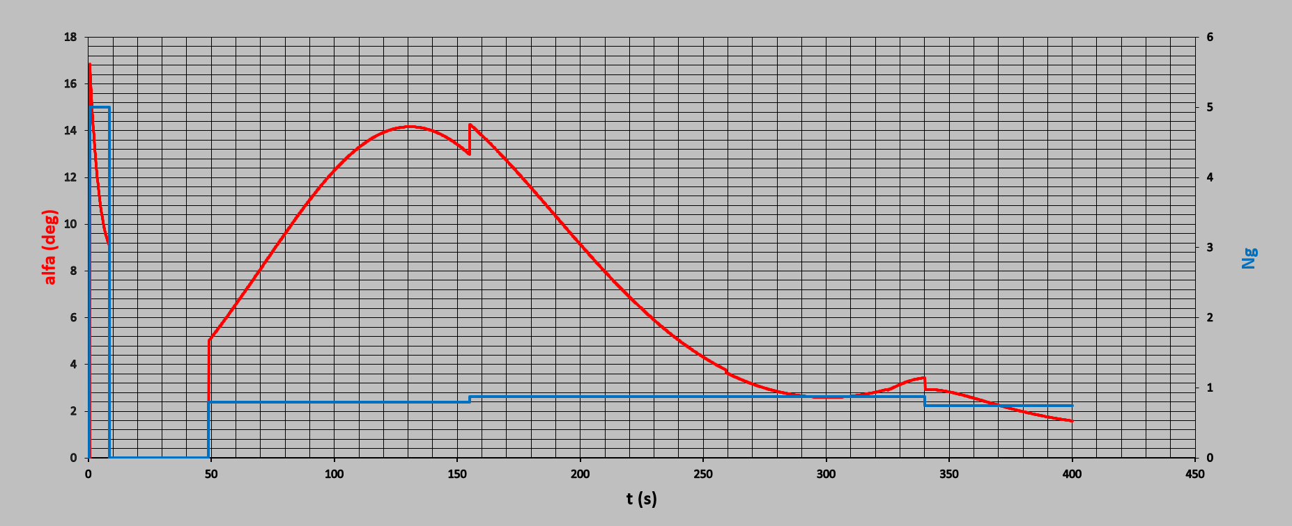
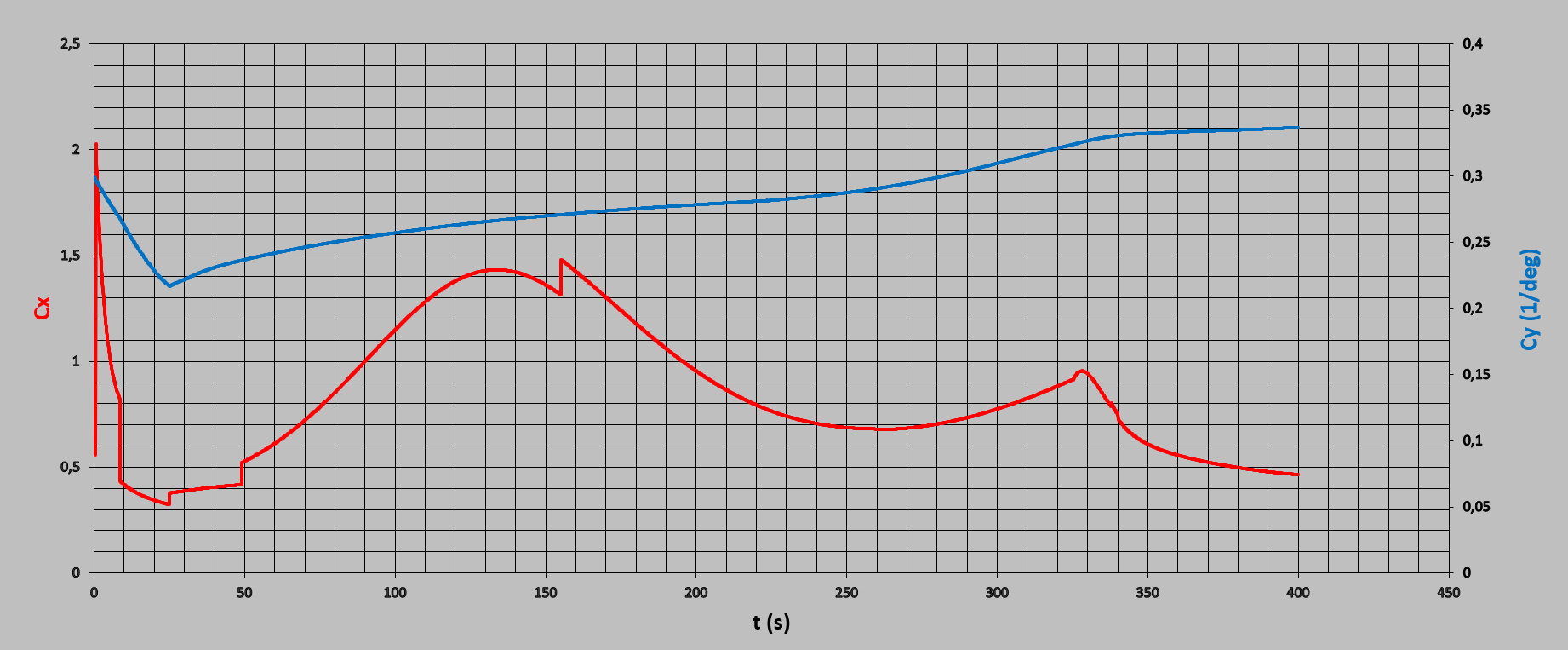
This one was tough but after several attempts I manged to get it flies that way It was all about when, how and how much to overload missile This is how Cx and Cy change with time Motor of course is not Spoonge Bob form but more as it should be This is change of dynamic pressure with time And at the end how trajectory looks like Of course this has nothing related with original Phoenix, NASA planned to use it for other purposes.
-
Thanks @draconus for time and efforts. If you manage to find some extra time, try to make this exact shot and I’m pretty sure there should not be some significant or any loft. I know in game lot of things are simplified, when I make some specific trajectory I put “in machine” program which makes integrating of mostly all mutually linked factors…and missile simply doesn’t like to go in loft.
-
We didn't understand each other well, these shots of mine are not shots with elevation (airplane pitch) but shots from horizontal fly and red parts of trajectory are parts where missile is overloaded, missile performs loft alone by its energy as it should be. Also this sample you made is not case we have. Launch range is 50nm (92,6km) , distance between fighter and target in moment of launch. Shot range in that case is something about 25 nm (46km) measured from starting point and that for me is point of launch. It is fligth time for missile of only 55 seconds or something like that
-
I will try to explain, with my poor English, this last scenario. This is loft, actually attempt to loft over such quick approaching target (in 55 seconds target travels 45,5 km). This starting 5g overload up there could be boundary condition for AIM-54, like said it is starting 25 degrees angle of attack for missile. Theoretically with overload >5g missile could in this scenario go over target altitude, with significant velocity shock performing such maneuver. And that is not all, to avoid situation that target slips under, missile should perform one more overloaded maneuver, now with negative angle of attack which will take additional velocity potential. Two such maneuvers will result with terminal velocity for sure less than managed 2,8M as presented. Eventually, if airplane will be in moment of launch with some elevation angle relatively to horizon, and by that missile in start will not need to handle with initial pushing nose from downward to upward, having starting elevation angle in opposite direction to what loft is looking for. And honestly, I’m not sure airplanes like F-14 made real launches of missiles like AIM-54 at such altitudes flying overloaded, flying with height gain, flying with axis elevated relatively to horizon. If this scenario would be with target flying a bit lower than these 22km and slower than these insane 2,8M, missile would go with this 5g in visually full blooded loft. However, these two sample shots are everything but not standard shots.


.png.7c23733dc04e6d2053bce1b012e2e694.png)
.png.d715a25012f528faa5d7e61389a6beca.png)