Vinc_Vega
-
Posts
641 -
Joined
-
Last visited
Content Type
Profiles
Forums
Events
Everything posted by Vinc_Vega
-
Hi Les, It's because the letters (and space) have not the same width. Using a fixed width font should do the right alignment. Alternatively you could program a kind of progress bar for that indication. https://steemit.com/utopian-io/@lapilipinas/arduino-blog-no-12-how-to-make-a-progress-bar-using-oled-display-and-rotary-encoder Regards, Vinc
-
Hi Les, To clear the screen from noise at startup, you should add a display.display(); command at the end of the Setup() routine. For the Adafruit Library, the easiest way to align text to the right is to print spaces in front of your numbers. If the numbers are less than 100 add one space, if lower than 10 add two spaces. Regards, Vinc
-

Ka50 BS3 - DCSBIOS ADF selector and AnalogMultiPos
Vinc_Vega replied to Jocman's topic in Home Cockpits
I'm not familiar with your switches and the connection. But for a 10 position switch maybe the all OFF position also counts as a step. Than there are 9 more positions to connect. So you need 8 resistors. Regards, Vinc -
Did you give all your slaves unique DCSBIOS_RS485_SLAVE IDs? Regards, Vinc
-
Here is a reference to choose from fonts for the U8glib: https://github.com/olikraus/u8glib/wiki/fontsize For better flexibility and results you may change to the newer U8g2 library. Regards, Vinc
-
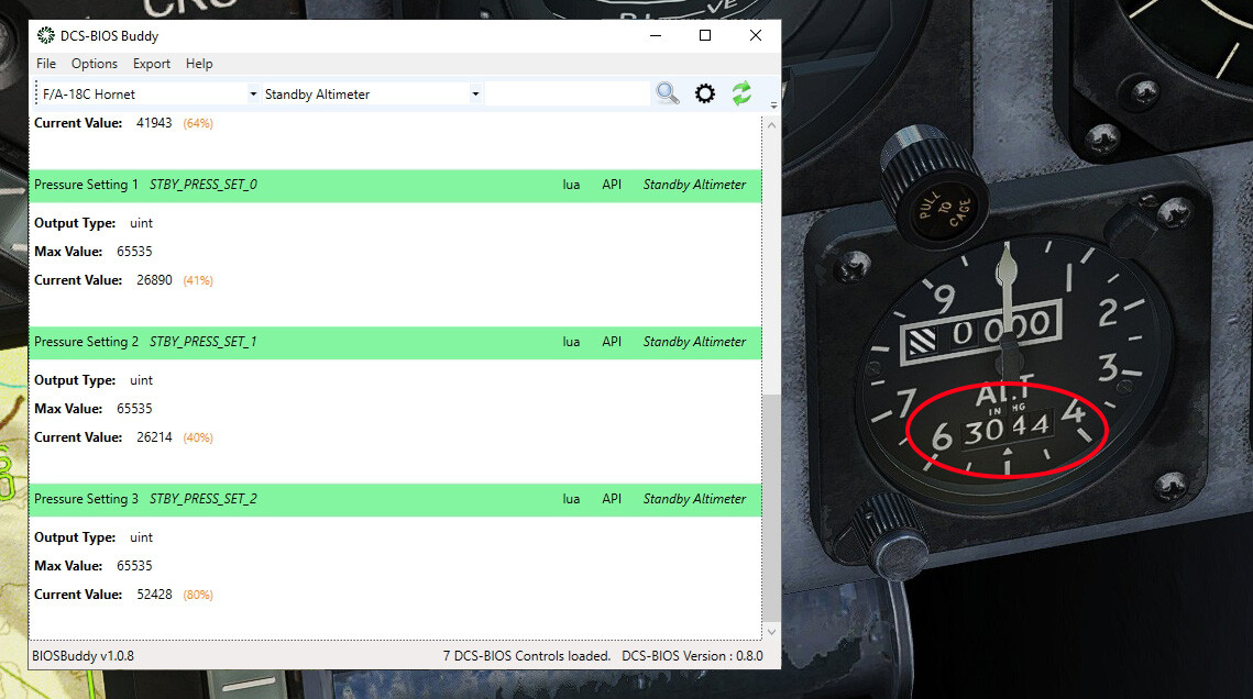
@No1sonuk He asked for the pressure setting values of the F-18 standby altimeter. I believe, those are the rolling digits in question. Regards, Vinc

-
That makes sense. Somethimes they split instrument digits into several arguments. Regards, Vinc
-
@Rolfez In the posts before it looks like U8glib is the graphics library in use in the zip file. The other sketches use the Adafruit GFX library. Regards, Vinc
-
Help With 7 Segment Display and A10 VHF Panel
Vinc_Vega replied to Kenpilot's topic in Home Cockpits
@No1sonuk I've found this link in the a.m. library description realy cool, to test code or some parts of it: https://wokwi.com/projects/344891439152366164 I didn't knew that online project before They even have a simulator for VS Code PlatformIO: https://marketplace.visualstudio.com/items?itemName=wokwi.wokwi-vscode Regards, Vinc -
Ah, okay. We usually use these cheap VID type automotive instrument steppers, including end stops, for direct connection to Arduinos. They don't pull much power and are good parts for Home Cockpit building Be careful if connecting other type of steppers without the use of additional driver boards. Arduino pins output 5V and are limited to max 50mA. But I think you already have that in mind for your 3 steppers project. If you want to display accurat values, than 41 element arrays make sense. But it will cost a lot of calculation power compared to only 10 or 15 elements. I don't believe that you can see a remarkable difference if you'd reduce the mapping resolution. If you want to drive more than one stepper from a single Arduino at the same time, there is a specific way to do so with the AccelStepper library. If you like, I'll than could post some code snippets here. I did that for two steppers at the same time. I think that driving 3 steppers may be possible. Regards, Vinc
-
@AlphaDecay Congratulations, well done! Nevertheless, I want to give some hints to consider for better performance of stepper motor gauges. As the stepper has physical end stops, why the need for a photoresistor to find the zero position? It is used once after power up and than never again. It's not an Altimeter with endless moving needles. A simple way is to run the stepper against the lower or the high end stop. Tell the stepper its position and than run to your physical gauge zero marking. You have to find the right step amount by experimenting. Tell the stepper the new zero position or use offsets. Ensure that the total way of the needle than never reaches behind the end stops. That's also the manufacturer's recommendation for calibration. For that procedure you may use a lower speed as in the main sketch. So after calibration a new max speed may be set. You don't need to set the speed everytime the poisition changes in the "void onVsiChange(...)" part, it already should be defined in the Setup section and than never changes. To effectively reduce calculation efforts and maybe thereby introduced jitter, I recommend a lower resolution of the mapping. Don't use more than 10 to 15 values per array. That will speed up your calculations. All values (newValue and steps to go) are not higher than 65535, so integer data types would reduce memory and calculation efforts. Especially the arrays reserve much more memory when using floats. Anyway, you don't need floats to produce the stepper counts. Mapping even should produce rounded values (integers). I hope that further reduces the mentioned jitters. Regards, Vinc
-
@AlphaDecay If you are familiar with Arduino coding, you could use Rob Tillaart's MultiMap library for non linear mapping problems. You just need two arrays of data (input and output). They have to have the same size to get mapped. I suggest to multimap the VSI integer to the scale value of the gauge (motor steps). Regards, Vinc
-
Help With 7 Segment Display and A10 VHF Panel
Vinc_Vega replied to Kenpilot's topic in Home Cockpits
@No1sonuk Yes, I know. From an electronic point of view you are fully right with the resistors at each segment. But I think they managed that in software within their library Link to the readme -> https://github.com/DeanIsMe/SevSeg?tab=readme-ov-file#current-limiting-resistors and an Extract from SevSeg.cpp Regards, Vinc -
Help With 7 Segment Display and A10 VHF Panel
Vinc_Vega replied to Kenpilot's topic in Home Cockpits
@No1sonuk In principle you are right, resistors at the common lines may cause (non noticeable) differences in brightness between the digits. But I think that has already been respected within the sevseg library. That’s what the switch resistorsOnSegments should be for, if set to false. Les resistors (components) keep the PCB footprint smaller. @Kenpilot Below code may be used in that way, but I haven’t checked it physically yet. Nevertheless, the compiler doesn’t complain and you have something to start from. You need to install the sevseg library (v3.7.1 at the time) to work with directly wired display modules. I’ve tried to comment as much as possible. I put in some extras into the sketch, like blanking the display if the radio is set to OFF and dimming according to the position of the LCP Signal Lights switch (night mode). You may adjust the value of led_intensity_dimm to your needs. Be careful with brightness values near or below 0, as that may cause flickering. Remember, that the setup of the wiring pins is {A, B, C, D, E, F, G, DP}. edited sketch: Regards, Vinc -
Help With 7 Segment Display and A10 VHF Panel
Vinc_Vega replied to Kenpilot's topic in Home Cockpits
Additionally you may have a look into the description of the sevseg library, as the wiring of the segments seems to differ a bit from the above linked example: https://github.com/DeanIsMe/SevSeg https://www.arduino.cc/reference/en/libraries/sevseg/ Edit: In principle it follows the scheme -> byte segmentPins[] = {A, B, C, D, E, F, G, DP}; and -> digitPins[] = {right most digit, second digit, ...}); anyway, a resistor of 330 Ohm for each ground line should be sufficient to protect your microcontroller Regards, Vinc -
Help With 7 Segment Display and A10 VHF Panel
Vinc_Vega replied to Kenpilot's topic in Home Cockpits
Hi Ken, that's the problem with things at Amazon, you buy what you see and have almost no exact data available at first glance. Just did a google for the model number 3621AH and found the website of the supplier XLITX. They provide the necessary data sheet for the corresponding display: http://www.xlitx.com/datasheet/3621AH.pdf For that display the pins already are connected internally. Therefore, you only have 10 inputs to the module: 7 pins for the segments, one for the dot and two for the ground of each digit. Here we are again with the 10 necessary outputs of your Arduino board. The wiring can be done like in the above linked example, with the exception that you only have two digits If you use the proposed wiring for the segment inputs, you only have to do the necessary adjustments in the Arduino sketch to the number of digits (here: numDigits = 2) and the digit pins connected (example: digitPins[] = {10, 11}). Try to run a test sketch to see if all connections work properly and you can see all segments. If all works well, we may develop the respective code snippets for DcsBios. Regards, Vinc -
Help With 7 Segment Display and A10 VHF Panel
Vinc_Vega replied to Kenpilot's topic in Home Cockpits
Hi @Kenpilot It depends on what you want your Arduino to do, else than displaying the preset channel. In principle it is possible to wire the display modules without a driver chip, but it's for the cost of a lot of Arduino outputs. For one digit you need 9 pins (7 pins for the segments plus the dot and the ground pin). For further modules you need one more pin per digit when muxing the common poles. Depending on the wiring, you may use prepared libraries. Have a look at the principles here: https://www.circuitbasics.com/arduino-7-segment-display-tutorial/ Scroll down to the four digit display section and imagine there were only two displays. You can see, that a two digit display still would need 10 Arduino pins. Remember, that you only get two digits displayed. If you use a driver, you only need the output for the bus, the chip is connected to. For example, the Max7219 only needs 3 digital pins of the Arduino. You can drive 8 of the seven segment displays from only one chip, and you may daisy chain up to 8 chips. You still spend only 3 digital outputs. You than also may use the ledcontrol library, that is tested with DcsBios. Unfortunately, you still have to wire all the display pins to the Max chip by yourself. If you don't want to create your own PCB and are not good at soldering, you may google for Max7219 driver modules and mis-use dot display PCBs to connect your display modules to. For example see these PCBs: https://www.ebay.de/itm/176175002297?chn=ps&_ul=DE&norover=1&mkevt=1&mkrid=707-134425-41852-0&mkcid=2&mkscid=101&itemid=176175002297&targetid=1404115578853&device=m&mktype=pla&googleloc=9042644&poi=&campaignid=17935704717&mkgroupid=139162549385&rlsatarget=pla-1404115578853&abcId=9301059&merchantid=7364532&gad_source=1&gclid=CjwKCAjwps-zBhAiEiwALwsVYZK1buzDymmAywiofEv6LD9YHi7HKQGiBEM3RVJCSg16tYNqXnuczRoCQi0QAvD_BwE Regards, Vinc -
Help With 7 Segment Display and A10 VHF Panel
Vinc_Vega replied to Kenpilot's topic in Home Cockpits
Hi @Kenpilot Do you want to connect the modules directly to the Arduino or by help of a driver chip? Regards, Vinc -
Help With 7 Segment Display and A10 VHF Panel
Vinc_Vega replied to Kenpilot's topic in Home Cockpits
Hi Ken, If you haven't bought yet, pls use the common cathode type LEDs. Have a look at the wirings for the common Max7219 driver chip here: https://wayoda.github.io/LedControl/pages/hardware.html#Wiring Edit: scroll down a bit for the 7 segment displays Regards, Vinc -
Have fun! Regards, Vinc
-
Thanks for your feedback. Regards, Vinc
-
Yes, there is no other switch in the cockpit that prevents the CMSP switches from moving. Like @No1sonuk wrote, they should move even in a cold & dark situation. Do a clean reinstall, like recommend above, and if that doesn't work, you also may download and make use of the latest DcsBios library for Arduino. Regards, Vinc
-
@Kenpilot I can't see any error within the script. To exclude that something is broken, you can go to the C:\Users\...\Saved Games\DCS.openbeta\Scripts directory and delete the DCS-BIOS folder and Export.lua (don't forget to backup your Export.lua). Than do a clean reinstall of DcsBios latest version https://github.com/DCS-Skunkworks/dcs-bios/releases/tag/latest Ensure that Socat or DcsBios-Bridge is running and try the CSMP script again. Regards, Vinc
-
Yes, you are right! The above example is for regular ON-OFF-ON switches and prepaid DcsBios snippets. If other switches are in use, the pins may be read and modified 'sendDcsBiosMessage" send. In other words, for that sketch and switches some objects from the switches.h file could be adjusted to send the respective messages. But I don't believe that's the real problem, because it's not the only panel with that kind of switches. @Kenpilot Please post the entire sketch to see if there is something blocking. Regards, Vinc
-
I finally found the time to do a quick test, just an Arduino Uno and some jump wires. The following sketch on the a.m. switches is working for me at pins 4 to 11 #define DCSBIOS_IRQ_SERIAL #include "DcsBios.h" /* paste code snippets from the reference documentation here */ DcsBios::Switch3Pos cmspDisp("CMSP_DISP", 4, 5); DcsBios::Switch3Pos cmspJmr("CMSP_JMR", 6, 7); DcsBios::Switch3Pos cmspMws("CMSP_MWS", 8, 9); DcsBios::Switch3Pos cmspRwr("CMSP_RWR", 10, 11); void setup() { DcsBios::setup(); } void loop() { DcsBios::loop(); } May you post the entire sketch for the CSMP to see if something broke the logic? Regards, Vinc