Vinc_Vega
-
Posts
641 -
Joined
-
Last visited
Content Type
Profiles
Forums
Events
Everything posted by Vinc_Vega
-
Yes, indeed the switches are ON-OFF-(momentary ON) switches but will act as if they were OFF-ON-MENU. A Switch3Pos only needs two pins of the Arduino (A & B) to represent all 3 positions, using the connectors A, GND and B as follows: pin A | pin B | status LOW | HIGH | (Off) returns 0 HIGH | HIGH | (On) returns 1 HIGH | LOW | (Menu) returns 2 This logic already has been implemented within DcsBios and you can use the statements from BORT for the four switches: DcsBios::Switch3Pos cmspDisp("CMSP_DISP", PIN_A, PIN_B); DcsBios::Switch3Pos cmspJmr("CMSP_JMR", PIN_A, PIN_B); DcsBios::Switch3Pos cmspMws("CMSP_MWS", PIN_A, PIN_B); DcsBios::Switch3Pos cmspRwr("CMSP_RWR", PIN_A, PIN_B); Regards, Vinc
-
You also may use the KY-040 modules, ready made encoders including resistors and capacitors and additional switch. example: https://www.az-delivery.de/en/products/drehimpulsgeber-modul Regards, Vinc
-
Just use ON-OFF-(ON) switches (same like with the IFF-Panel). These are wired to two different Arduino pins. If using the Switch3Pos option DcsBios already knows how to code. Therefore, either 0 or 2 is send by DcsBios, representing the two end positions (Low at one pin, High at the other pin). DcsBios even knows if the signals are High at both pins, that the switch is in middle position (sending 1). Edit: If you really have OFF-ON-ON switches, you may have to change the order of sending the messages. Double check your switches, Ground is the middle pin, end positions are at first and third pin. Regards, Vinc
-
 @Jocman Yes you can if @No1sonuk not already did. At least someone can walk through the source code and look if there's an issue within the RS485 definitions. Regards, Vinc
 -
@TrevorMcNeill I've found the issue. Uncommenting the "print all addresses and values to the monitor" function solved the buffering problem for me Best regards, Vinc
-
I have no RS485 bus for testing at the time. Sorry, I can't help anymore. Regards, Vinc
-
@Jocman Seems to be an internal DcsBios issue. try the "manual" solution. Regards, Vinc
-
@No1sonuk You are right, we get rid of the "DcsBios::" preposition but have to use the "sendDcsBiosMessage" with a lower case "s". @Jocman Both versions (a and b) work for me in the cockpit of the Ka-50 version 2: a) Use of the preformed BORT snippets b) Manually sending the switch inputs via Socat Best Regards, Vinc

-
@Simpit Solution: 1) Download the DCS-BIOS Nightly from https://github.com/DCS-Skunkworks/dcs-bios/releases/tag/latest 2) Go to the C:\Users\...\Saved Games\DCS.openbeta\Scripts directory and delete the DCS-BIOS folder and Export.lua (edit: don't forget to backup your Export.lua) 3) extract the content from the Nightly zip file into the C:\Users\...\Saved Games\DCS.openbeta\Scripts directory Regards, Vinc
-
Confirmed! One cannot longer send commands via DcsBios. Nevertheless, BORT is still able to readout data from the simulation, so the server seems to be alive. Regards, Vinc
-
@Jocman Edit: try to update to the latest built of DcsBios, than check again. Regards, Vinc
-
@Jocman No, you don't need those DcsBios snippets for inputs as you can readout the Arduino pin - digitalRead(pin). Than make a decision, if the input is high, tryToSend a 0, else tryToSend 1 with the above commands. Inverse logic is because the switch is closed to ground. (Unfortunately, I'm not at my laptop over the weekend, so I have to guess and type at my cellphone) Regars, Vinc
-
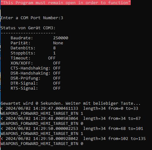
@Jocman You could use commands for the switch in "if" statements like DcsBios::tryToSendDcsBiosMessage("WEAPONS_FORWARD_HEMI_TARGET_BTN", "1"); and DcsBios::tryToSendDcsBiosMessage("WEAPONS_FORWARD_HEMI_TARGET_BTN", "0"); Regards, Vinc
-
Sorry, the hex addresses are for output only. My fault! Yes, for that function it would be 0x1916. Regards, Vinc
-
What if you used the hex address instead of the signal name in the sketch? Regards, Vinc
-
Arduino Error Code for DCS Bios A10 CMSP Display Sketch
Vinc_Vega replied to Kenpilot's topic in Home Cockpits
In that case the spaces could be removed from the string. Than they should fit into the 16 character lines Regards, Vinc -
Arduino Error Code for DCS Bios A10 CMSP Display Sketch
Vinc_Vega replied to Kenpilot's topic in Home Cockpits
@Kenpilot Try to change the code in the header to that of a 16x02 display. LiquidCrystal_I2C lcd(0x27,16,2); Regards, Vinc -
Need help exporting the magnetic heading using DCS-Bios
Vinc_Vega replied to Bacab's topic in Home Cockpits
@Bacab For the math you may use the values from the ...\DCS World OpenBeta\Mods\aircraft\F-16C\Cockpit\Scripts\Instruments\StandbyCompass.lua file. The deviation is layed down in radians, so I think it would be possible to calculate something usefull. Regards, Vinc -
Need help exporting the magnetic heading using DCS-Bios
Vinc_Vega replied to Bacab's topic in Home Cockpits
Hi Bacab If you have a look into the DcsBios export tools like Bort or so, there are no outputs of the F-16 HSI. The standby compass is not even a part of those tools. So at the time there seems to be no possibility for direct export. You have to do math to get the mag heading or wait until the respective DcsBios F-16 lua files are expanded accordingly. Regards, Vinc -
Did you already know of that? Regards, Vinc
-
Arduino Error Code for DCS Bios A10 CMSP Display Sketch
Vinc_Vega replied to Kenpilot's topic in Home Cockpits
Hi Ken, Here is a link to a description, from where you can start on with your display type. https://community.microcenter.com/kb/articles/649-inland-1602-i2c-module Follow the instruction for wiring and upload the “Hello World” sketch to see if everything works as expected. If you read “Hello World” and "123456!" at your display, go on and adjust the header of the CSMP sketch. The libraries and the LiqidCrystal lcd object have to be changed from #define DCSBIOS_IRQ_SERIAL #include "DcsBios.h" // include the library code: #include <LiquidCrystal.h> // initialize the library by associating any needed LCD interface pin // with the arduino pin number it is connected to const int rs = 12, en = 11, d4 = 10, d5 = 9, d6 = 8, d7 = 7; LiquidCrystal lcd(rs, en, d4, d5, d6, d7); to include the I2C library (Wire.h) and the to be installed LiquidCrystal_I2C library. #define DCSBIOS_IRQ_SERIAL #include "DcsBios.h" // include the library code: #include <Wire.h> #include <LiquidCrystal_I2C.h> LiquidCrystal_I2C lcd(0x27,20,2); // set the LCD address to 0x27 for a 20 chars and 2 line display Depending on the I2C backpack, the address may have to be changed from 0x27 to 0x20. If both addresses do not work, upload an I2C scanner sketch and read out the correct display address at your Arduino IDE serial monitor. https://gist.github.com/tfeldmann/5411375 Let the DcsBios code snippets as they are /* paste code snippets from the reference documentation here */ // ----- print the first line to the LCD display ----- void onCmsp1Change(char* newValue) { lcd.setCursor(0,0); lcd.print(newValue); } DcsBios::StringBuffer<19> cmsp1Buffer(0x1000, onCmsp1Change); // ----- print the second line to the LCD display ----- void onCmsp2Change(char* newValue) { lcd.setCursor(0,1); lcd.print(newValue); } DcsBios::StringBuffer<19> cmsp2Buffer(0x1014, onCmsp2Change); Within the SETUP section you finally need to adjust the initialization procedure void setup() { DcsBios::setup(); lcd.begin(20, 2); lcd.clear(); } to the initialization of the above linked “Hello World” sketch void setup() { DcsBios::setup(); lcd.init(); // initialize the lcd lcd.init(); lcd.backlight(); lcd.clear(); } btw. I have no clue why they twice use lcd.init() The LOOP section remains as it is. void loop() { DcsBios::loop(); } That already should do it. Regards, Vinc -
Arduino Error Code for DCS Bios A10 CMSP Display Sketch
Vinc_Vega replied to Kenpilot's topic in Home Cockpits
Hi Ken, as already told, you have to adjust the sketch to use it with the I2C interface of your display. Here is a link to the library https://www.arduino.cc/reference/en/libraries/liquidcrystal-i2c/ First try to upload the examples to get familiar with the display. If everything works fine, rework the sketch accordingly. Regards, Vinc -
Thank’s for the update! I asked because still planning to get panels working based on Raspberry Pi, but still am at the beginning of the steep learning curve for Python and Pygame. As I’m old-fashioned, I probably need to read more books on that topic – using AI is no option to me. My sketches are based on reverse engineering FSIan’s example for the CDU display https://github.com/jboecker/python-dcs-bios-example/tree/master Parts of the A-10C HSI already are working. Thereby, the Pi is connected by a LAN cable to the PC in UDP mode. I didn’t get a TCP connection between my Laptop and the Pi yet. Haven’t tried the Wi-Fi option as well. Still trying to iron out some issues. For example, when pausing the sim or exiting the mission the HSI still turns a few seconds. My impression is, that the values are stored somewhere in a buffer and that slows down the display. You may see some delay between hearing the clicks in the above clip and the response of the arrows. The longer the online time, the more is the delay. Best Regards, Vinc
-
Nice work with the help of AI. Can't wait to see more from you. The clip is a little to dark to see what's really going on. Does it run on another Windows PC or a Raspberry Pi? Regards, Vinc
-
These are no typical LEDs as they already include a resistor for 5V applications. I think that they are for direct wiring to Arduino boards. Maybe you have to interpolate the RSet to a Max7219 chip for 5V and 17mA from the data sheet. Than 10kOhm sounds plausible to me. Your brightness should already be set to max from the software side: setIntensity(int addr, int intensity), where 15 is the max intensity value. How is the brightness if you direct supply a LED from an Arduino with 5V compared to one at the Max-chip? Best regards, Vinc