Vinc_Vega
-
Posts
641 -
Joined
-
Last visited
Content Type
Profiles
Forums
Events
Everything posted by Vinc_Vega
-
The resistor is to limit the forward voltage and current, supplied from the Max7219 to ALL the LEDs. So you don't need any more resistors for each LED. Please read the documentation in the hardware part of the ledcontrol pages on how to select that one resistor (RSet). You still have to know the forward voltage and allowed current for your LEDs. https://wayoda.github.io/LedControl/pages/hardware.html#SelectRSet Edit: According to the table you already should have 40mA output at 3V for each LED when using a 10kOhm resistor Btw. the brightness of your LEDs even may be controlled by software. It's then easiest done with the ledcontrol library. https://wayoda.github.io/LedControl/pages/software.html Regards, Vinc PS: Hey Joe, you also may PM me
-

DCSBIOS and BORT update and problem with the snippet (Ka-50 module)
Vinc_Vega replied to Jocman's topic in Home Cockpits
Since a few days I'm seeing those delays in the response too, even with a single USB connection when changing the frequency in the Sim cockpit (A-10C II). Sometimes it helps to reconnect the COM port. No idea what has been changed in the programme. Regards, Vinc -
DCSBIOS and BORT update and problem with the snippet (Ka-50 module)
Vinc_Vega replied to Jocman's topic in Home Cockpits
Edited: For your second issue, you may use the option to tell Bort not to use Address Constants. While in the first example you call an integer of r800Freq1Rot, you are better with the Frequency String statement of the second example for displays. Regards, Vinc -
I'm afraid you have to ask the programmers for the changes Regards, Vinc
-
They say that the network protocol has been changed Maybe that's a reason? Edit: another option is, that your export.lua has been overwritten by the update Regards, Vinc
-
So why don't you try the RS485 bus option and reserve the USB ports only for panels that need higher bus speed? Regards, Vinc
-
@Strale Hi I decided not to try the Nano Every as I had enough of the "regular" Nanos available and ESP32 modules in several form factors. Anyway, other members reported of unsolved problems. Sorry! Maybe @lesthegrngo or @outbaxx have more experience with that kind of chips. Best regards, Vinc
-
Here you can find the discussion on how a slave Mega should be connected https://forum.dcs.world/topic/310930-maximising-the-use-of-arduino-nanos-max-switch-connections-possible/#comment-5083746 You also may have a look into previous RS485 related discussions. I recommend the second layout from that posting https://forum.dcs.world/topic/208455-dcs-bios-over-rs485/?do=findComment&comment=3926198 Regards, Vinc
-
For me the Updater (version 2.16.3.18) is running forever. Click at "Cancel" doesn't skip the updater but stops the program. No access to DCS so far. I updated DCS to the latest Open Beta last weekend and started without problems until today. Please help! Regards, Vinc Edit: SOLVED Repair procedure accoding to https://www.digitalcombatsimulator.com/en/support/faq/709/
-
@Kenpilot not yet perfect but something you can play with and try your displays ... One Max7219; displays 0 to 5 for the frequency and 6 and 7 for the presets PS: in case of questions, just PM me. Regards, Vinc Edit: corrected code of leading digits for frequencies below 100.000 and presets less than 10
-
If your chip is a Max7219 or so, you could use the ledcontrol library for your displays. https://wayoda.github.io/LedControl/pages/software.html#7Seg Regards, Vinc
-
It's really hard to get 16 segment displays these days. You made your own Regards, Vinc
-
Need help with code for x27 stepper motor (Solved)
Vinc_Vega replied to Udav_Kaa's topic in Home Cockpits
@Vzhik Is your stepper motor repeatedly going to zero position or is the Uno rebooting inflight? Are you sure, that the gauge address 0x10a0 is correct? A look into the dcs-bios-arduino-library reveals hex code 0x184E for the Ka_50_VARIO_SPEED. If the problems remain, you may remove the stepper object and start separate coding for each stepper motor. Pls find below an example for a two-stepper gauge: You also may get rid of the driver board and use the direct connection to check if the problem is still there. AccelStepper stepper(AccelStepper::FULL4WIRE,4,5,6,7); // stepper on pins 4, 5, 6 and 7 That should be a much simpler approach for a single stepper gauge. Regards, Vinc -
Can't find it at the linked discord. Does anyone has a direct link to these sketches please? Regards, Vinc
-
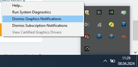
Try to right click on the small icon in the task bar (SOLIDWORKS Resorce Monitor) and choose "Dismiss Graphics Notifications". Else here are some useful links for tweaking the performance: https://help.solidworks.com/2024/English/SWConnected/swdotworks/HIDD_OPTIONS_PERFORMANCE.htm You also may force the Software to use your graphic card and adjust the performance. https://www.mlc-cad.com/solidworks-help-center/how-to-force-solidworks-to-use-your-graphics-card/ My laptop (OMEN by HP 17) is from 2016 and still bears a Nvidia 1070 and Intel Core i7-6700HQ @2.6 GHz. System is Win10 64bit, RAM memory has been upgraded to 32GB. No problems so far with SolidWorks actual maker version. Regards, Vinc

-
Seeking A10 CMSC and CMSP Display Suggestions
Vinc_Vega replied to Kenpilot's topic in Home Cockpits
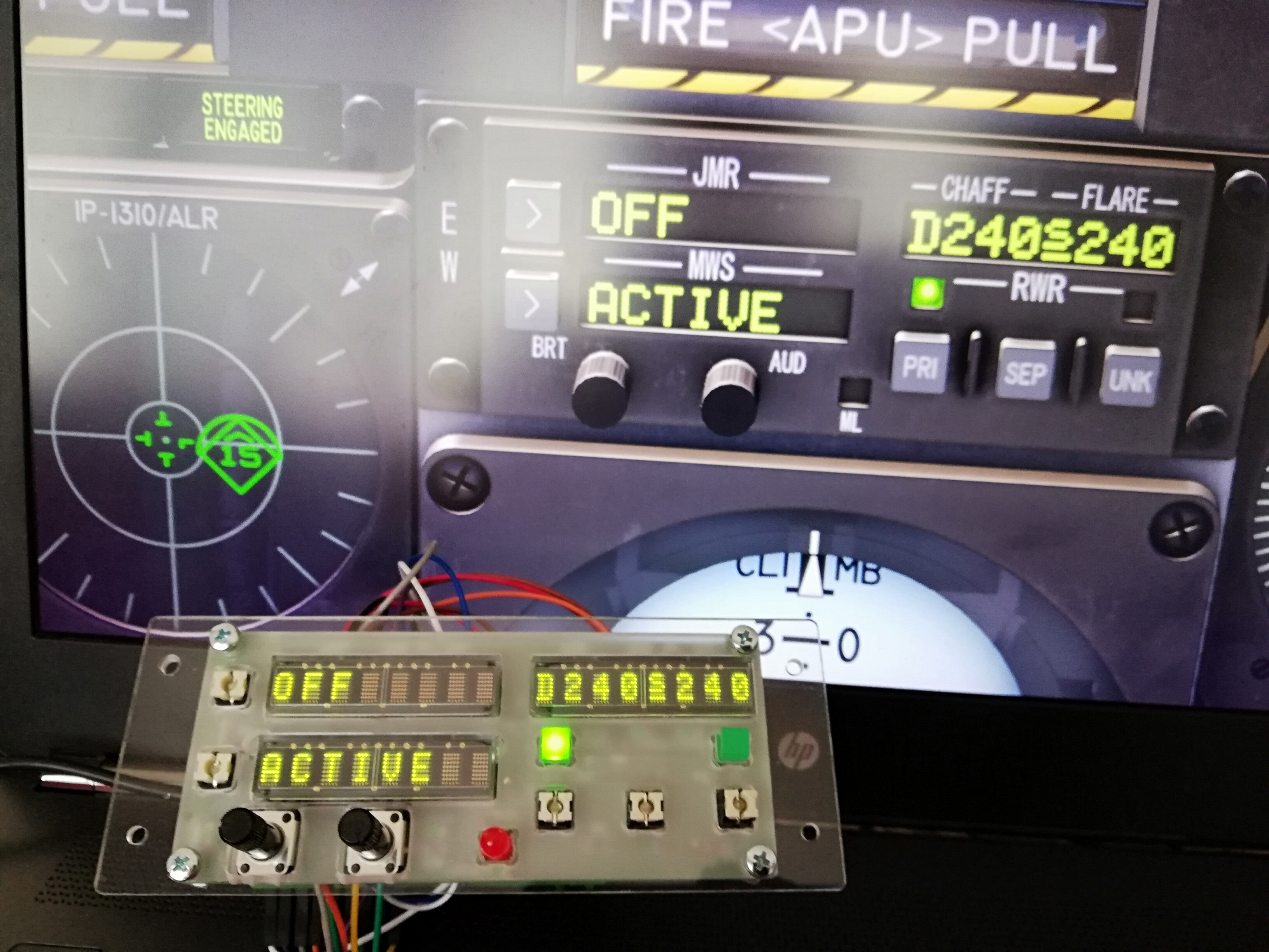
How about something like 20x2 LCD display for the CMSP? Btw. here's another "overdressed" work, this time the CMSC panel with LED matrix displays, but still unpainted. For the A-10 the font had to be edited. Regards, Vinc
-
@Enabler Sorry for the late reply, some changes in the Skunkworks fork do that the code no longer compiles if a separate analogWrite library is in use for ESP32 chipsets. Just delete the #include "analogWrite.h" line and add the following line below the #define DCSBIOS_DEFAULT_SERIAL entry #define DCSBIOS_DISABLE_SERVO Regards, Vinc
-
@scorpyq The above download compiles with GFX Library for Arduino and TFT_eSPI library for the 2.1 inch round ST7701S display. If you have problems with ESP32 chips and DcsBios, try to add the following line below the DCSBIOS_DEFAULT_SERIAL entry: #define DCSBIOS_DISABLE_SERVO Follow Adafruit's setup guide for the Qualia ESP32-S3 setup in the Arduino IDE and the library installation: https://learn.adafruit.com/adafruit-qualia-esp32-s3-for-rgb666-displays/arduino-ide-setup https://learn.adafruit.com/adafruit-qualia-esp32-s3-for-rgb666-displays/arduino-library-installation I put the following lines into my board manager and choose the Adafruit Qualia ESP32-S3 RGB-666 from the esp32 list. https://adafruit.github.io/arduino-board-index/package_adafruit_index.json https://dl.espressif.com/dl/package_esp32_index.json https://raw.githubusercontent.com/espressif/arduino-esp32/gh-pages/package_esp32_dev_index.json https://raw.githubusercontent.com/espressif/arduino-esp32/gh-pages/package_esp32_index.json To launch the bootloader, you have to hold down Boot0 and press Reset of your board. Than get sure to use the actually shown COM port within the Arduino IDE. Regards, Vinc
-
Hi Joe, I did not mean the Rs458 nor bus addresses but those from the DscBios internal arguments. If they weren't changed by an update, your old panels should work. If you see strange behaviour that could be a reason. Kind regards and always a happy landing. Vinc
-
Looks pretty cool Regards, Vinc
-
Hi Joe, This is an issue of DCS:World updates. To make it short, YES you can, but it depends on if the addresses have changed. Edit: It's another matter if you want to compile the sketches again. Then it's better to use the FP files, because Hub is not up to date. Best Regards and Happy Easter, Vinc
-
The pulldown resistor is not required. It has been recommended somewhere here in the forum in case you have problems to receive data (RE low = receiver enabled). As No1sonuk already wrote, the capacity is to reduce noise in the power supply. It is optional too. Regards, Vinc
-
My latest board design also features jumpers on both lines (RX and TX) leaving me the opoprtunity to programm a chip without removal. It works good. Regards, Vinc
-
Arduino Error Code for DCS Bios A10 CMSP Display Sketch
Vinc_Vega replied to Kenpilot's topic in Home Cockpits
@No1sonuk How can we tell Bort to use the new library? Edit: I found no way to tell Bort to use the Addresses, instead of that control-reference seems to use those names: .../Saved Games/DCS.openbeta/Scripts/DCS-BIOS/doc/control-reference.html Regards, Vinc -
Arduino Error Code for DCS Bios A10 CMSP Display Sketch
Vinc_Vega replied to Kenpilot's topic in Home Cockpits
Hi Ken, to output the data, you cannot use the simplified code fragments. Unfortunately, it's a bit trickier. Within the sketch header you have to declare the display driver and then initialize it in the setup loop. If you don't know how to do this, please provide us with your display description (kind of driver) and how it is connected to your microcontroller (the wiring). For a simple 2x16 character LCD module the ->LiquidCrystal library<- should do most things for us. Please try the examples to ensure that the display works correctly for you. That kind of display mostly is initialized by the "lcd" object and you may print to either the first (0) or the second (1) line. The Arduino code in the DcsBios section than should look something like this: // ----- print CMSP Display Line 1 to the LCD display ----- void onCmsp1Change(char* newValue) { lcd.setCursor(0,0); lcd.print(newValue); } DcsBios::StringBuffer<19> cmsp1Buffer(0x1000, onCmsp1Change); // ----- print CMSP Display Line 2 to the LCD display ----- void onCmsp2Change(char* newValue) { lcd.setCursor(0,1); lcd.print(newValue); } DcsBios::StringBuffer<19> cmsp2Buffer(0x1014, onCmsp2Change); Regards, Vinc