Vinc_Vega
-
Posts
641 -
Joined
-
Last visited
Content Type
Profiles
Forums
Events
Everything posted by Vinc_Vega
-
 @sharkfin61 Char number 3 of the string (from left to right, first is 0) may be spared, because it's the decimal point. Therefore, the colon of respective digit can be switched on (set to true). Count the displays from right (0) to left (7). try something like this for "_012.456_" //SECOND - 8 DIGIT 7 SEGMENT DISPLAY - UHF RADIO (CODE) void onUhfFrequencyChange(char* newValue) { lc2.setChar(0,7," ",false); // display 7 is off (line may be deleted) lc2.setChar(0,6,newValue[0],false); lc2.setChar(0,5,newValue[1],false); lc2.setChar(0,4,newValue[2],true); lc2.setChar(0,3,newValue[4],false); lc2.setChar(0,2,newValue[5],false); lc2.setChar(0,1,newValue[6],false); lc2.setChar(0,0," ",false); // display 0 is off (line may be deleted) } DcsBios::StringBuffer<7> uhfFrequencyBuffer(0x1180, onUhfFrequencyChange); Regards, Vinc
 -
Sorry, I can't help anymore without the proper hardware. Ssd1322 displays are still on their way. Regards, Vinc
-
Something like that, but you have to use the old u8g library. Regards, Vinc
-
No, it's written for ESP32 microcontrollers. If you want the sketch for Uno or Mega, you have to go back a few more pages of that post. Regards, Vinc
-
Failure description doesn't make sense to me. You can either use the u8g2 or the old u8g library. Your Setup loop is empty and does not initialize any display. Furthermore this loop has to be closed by "}". Why don't use the sketch from the above linked post? Regards, Vinc
-
@uncino Try a clean re-installation of the library: https://github.com/olikraus/u8g2/wiki/u8g2install
-
Hi @uncino gfx library is not in use for that project. U8g2 for Arduino can be downloaded from here: https://github.com/olikraus/U8g2_Arduino/archive/master.zip For the sketch you have to go two pages back in this post and reveal the hidden contents: Regards, Vinc
-
@Snakedoc According to the description in the pic from Amazon (see below), if R5 and R8 are connected, it should have set to the 4 wire SPI. That combination I can see in your picture. Did you de-solder R6 and put the resistor in place of R5 ? If that doesn't work, we have to do more investigations when my displays have arrived. Regards, Vinc
-
Hi @Snakedoc 1) for the test I used the LOLIN S2 Mini board from the esp32 menu in the Arduino IDE to upload a sketch. For details see here: https://www.wemos.cc/en/latest/tutorials/s2/get_started_with_arduino_s2.html 2) The driver seems to be the right one (4 wire SPI), R0 and R2 is the rotation of the screen. According to the display's pinout found at Aliexpress, I recomment to connect it as follows: Display S2 Mini 1 VSS GND 2 VCC 3.3V 4 CLK 7 (SCL) 5 DIN 11 (MOSI) 14 DC 6 (can be changed to any digital pin) 15 RES 8 RST (can be changed to any digital pin) 16 CS 12 CS (can be changed to any digital pin) I've ordered a pair of the SSD1322 displays from Aliexpress, but it'll take a while to get it from China. I'll give an update when they have arrived. Regards, Vinc
-
@Snakedoc I organized an ESP32 S2 mini over the weekend and plugged it to my SH1122 display (256x64 px). There is a verry good reaction time, no delays between page flipping. Therefore, the microcontroller is good for that purposes and you don’t have to change it. If there still are timing issues or lags, you really may try other graphic drivers (like the below "full buffer 4 wire hardware SPI driver"). My pinout to the display is as follows (hardware SPI): GND -> GND VCC -> 3.3V SCL -> 7 (SCK) SDA -> 11 (MOSI) RST -> 8 DC -> 6 CS -> 12 (CS) I use the following line within my sketch U8G2_SH1122_256X64_F_4W_HW_SPI u8g2(U8G2_R0, /* cs=*/ 12, /* dc=*/ 6, /* reset=*/ 8); Regards, Vinc
-
Rotary Encoder W/Switch, LED and Arduino Help Please
Vinc_Vega replied to Kenpilot's topic in Home Cockpits
Hi Ken, I did a quick breadbord test and confirm your LED wiring and the code snippets. If you want to have the LED on when a rotary is active (un-mute), the LEDs must be controlled by their positive ends. All GND pins therefore can be connected. Like @No1sonuk already mentioned, the LED addresses must be different. Like: DcsBios::LED intIntUnmute(0x1194, 0x8000, 13); // a LED shows if the INT volume adjustment is active DcsBios::LED intFmUnmute(0x119c, 0x8000, PIN); // for the FM volume DcsBios::LED intVhfUnmute(0x11a6, 0x0001, PIN); // for the VHF volume and so on If you are not sure for a dedicated address, you may compare it to the regular output statements. // regular statement for the VHF volume unmute (0x11a6, 0x0001) void onIntVhfUnmuteChange(unsigned int newValue) { /* your code here */ } DcsBios::IntegerBuffer intVhfUnmuteBuffer(0x11a6, 0x0001, 0, onIntVhfUnmuteChange); // LED address for the VHF volume unmute (0x11a6, 0x0001) same as above DcsBios::LED intVhfUnmute(0x11a6, 0x0001, PIN); For the rotaries you have to see, what works best with your setup. The rest of the code should work as expected. You also may remove the #include "LedControl.h" statement from this sketch. Have a nice weekend. Regards, Vinc Edit: find below a list of the Intercom Panel Unmute LED statements from Bort DcsBios::LED intAimUnmute(0x11a6, 0x0004, PIN); DcsBios::LED intFmUnmute(0x119c, 0x8000, PIN); DcsBios::LED intIffUnmute(0x11a6, 0x0008, PIN); DcsBios::LED intIlsUnmute(0x11a6, 0x0010, PIN); DcsBios::LED intIntUnmute(0x1194, 0x8000, PIN); DcsBios::LED intTcnUnmute(0x11a6, 0x0020, PIN); DcsBios::LED intUhfUnmute(0x11a6, 0x0002, PIN); DcsBios::LED intVhfUnmute(0x11a6, 0x0001, PIN); -
Rotary Encoder W/Switch, LED and Arduino Help Please
Vinc_Vega replied to Kenpilot's topic in Home Cockpits
Hi Ken, I'll do a check tonight and update this message. For now, you may check the wiring as the LEDs mostly are controlled by their GND pins. Regards, Vinc -
Before going to change the microcontroller, did you try to switch to a full framebuffer SPI hardware driver for that display? U8G2_SSD1322_NHD_256X64_F_4W_HW_SPI(rotation, cs, dc [, reset]) [full framebuffer, size = 2048 bytes] If you are not sure for your SPI connection, I already ->here<- explained how to read out the hardware SPI pins for your board in use. You also may try other combinations for the display driver to limit its buffer size: https://github.com/olikraus/u8g2/wiki/u8g2setupcpp#ssd1322-nhd_256x64 Regards, Vinc
-
Why don't you use the hardware SPI pins and the respective display driver? That should speed up the thing a bit. 11 MOSI 9 MISO 7 Clock 12 Chip Select If it's still too slow, you may try a full dual core ESP32 dev board. Something like below should do it. Regards, Vinc https://www.espressif.com/en/products/devkits/esp32-devkitc
-
If you don't see the ESP you probably have a problem with ESP USB drivers or the upload was not successful. Have you tried to load a simpler sketch and confirm running and USB connection? I didn't experienced that until now but haven't used a S2 mini board yet. Sorry for that. Regards, Vinc Edit: It seems that there are common problems to establish an USB connection with that kind of board and found a recommendation with google: "While it’s connected via USB, press and hold the BOOT button. Press and release the RESET button, then release the BOOT button. This puts the S2’s and S3’s USB port into serial mode. If there’s nothing already flashed to it then you may need to do this to get it to show up as a USB device." No idea if that works for you.
-
@Hammer3246 Just put the following line into the void_setup() section, below the display.begin(...) statement: display.setRotation(0); //rotates display on OLED, values: 0=0, 1=90, 2=180, 3=270 degrees Rotation values have to be adjusted to your needs. Regards, Vinc
-
Hi Les, not a solution, but try to dive into documentation of the USB Power Delivery Standards (PD). I don't think that hubs with more than the standard 5V are easily adaptable to home made applications. Regards, Vinc
-
I used an old plan to built my frames a few years ago. My angles read as follows: R/H Console: 95° and 164° L/H Console: 95°, 176° and 165° Angle between inner (horizontal) and outer panels is 162° for both consoles. Regards, Vinc
- 1 reply
-
- 1
-

-
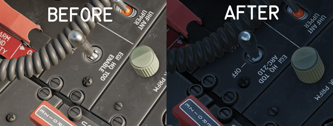
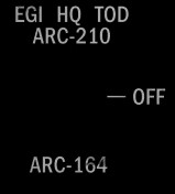
Hi everyone, I wonder if someone already noticed, that the “EGI HQ TOD” Switch of the Antenna-Panel in the A-10C II has been changed? Before there was a two positions switch (ENABLE – DISABLE), but now the panel has markings for three positions (ARC-210 – OFF – ARC-164). See extracted cokpit texture below. The physical switch within the cockpit still has two positions (ARC-210 - OFF) and that is what is exported by DCS-Bios. The ARC-164 position cannot be switched. As the panel obviously is not functional in the simulator, this should not effect the gameplay. Maybe that has been changed with implementation of the ARC-210 radio, that still is not fully documented by the developers. Best regards, Vinc

- 1 reply
-
- 1
-
-
Compared to the 256 kB/ 16 MHz of the Mega 2560, an ESP32 has much more memory available and a clock speed up to 240MHz. Unfortunately, the ESP32 is (yet) not compatible with the DCS-Bios R485 bus and has less I/O pins than a Mega. For more information, see the below link https://www.makerguides.com/esp32-vs-arduino-speed-comparison/ Regards, Vinc
-
Perfect!
-
Using the U8g2-library's Page Buffer instead of the Full Buffer brings back the full display. That already is part of the adapted code. (Reveal hidden contents) The export of the inverted text seems to be some kind of workaround. Here additional bytes are used to steer the inversion. Therefore, my code searches every long line of text for the additional characters and then has to analyse every byte bitwise for inversion commands. If an inverted bit has been found, the respective character from the text line is read and replaced within the original text. That takes a while, even for a powerful ESP32 chipset. I than removed the additional steering bytes from the line so, that it is not analysed again in the next loop. That already is some optimisation, but I’m not a professional programmer. Even for the asterisk the steering bytes sometime are not exported. Furthermore, the number of pixels (256 x 64) has to be handled by the library every time the display is refreshed. It may help if somebody claims the problematic inversion of the DED line characters within the developer’s forum and ask for more support for cockpit builders. Regards, Vinc PS: Additionally, the above linked code must be changed like posted here:
-
Have you tried the author's suggestions for that kind of displays? https://github.com/olikraus/u8g2/issues/2039 Regards, Vinc
-
Hi Les, Have a look at this guy's project! https://hackaday.io/project/186478-arduino-weighing-machinescale-with-analog-showin He uses an analogue 5V voltmeter, steered by Arduino PWM signals (remember: 0 to 5 Volts), to fake a weight scale. Within his code the output simply reads analogWrite (6,WEIGHT); while 6 is the output pin and WEIGHT is the PWM value from 0 to 255. https://cdn.hackaday.io/files/1864787978274752/CODE FINAL.txt There seems to be no need for a library So if your gauges are designed to work with 5V or less, it should be possible to move the pointers. It's than more or less a question of their calibration. Regards, Vinc
-
Yes, the TFT_eSPI library is still not full compatible with Esp32 board manager version 3 and above. Regards, Vinc